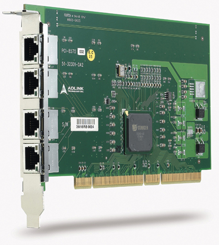
- Purpose‑Built for PCI/PXI Extension: Enables transparent communication between a host PCI system and a remote PXI or CompactPCI chassis up to 10 m away.
- High‑Speed Serial Transmission: Supports StarFabric‑based serial interconnects operating at 622 Mbps per differential pair, providing up to 2.5 Gbps full‑duplex bandwidth.
- Shielded Twisted‑Pair Construction: Eight pairs of individually shielded twisted copper wires minimize electromagnetic interference (EMI) and maintain signal integrity over long distances.
- Robust Connector Interface: Equipped with a 24‑pin DVI‑D or RJ‑45‑type connector (depending on system configuration) for secure, low‑loss connectivity.
- Full PCI Bandwidth Support: Maintains complete 32‑bit/33 MHz PCI bandwidth (132 MB/s) or up to 528 MB/s for 64‑bit/66 MHz PXI‑8570 configurations.
- Hardware and Software Transparency: No additional drivers required; all devices in the extended chassis appear as local PCI devices to the host system.
- Compatibility: Designed for use with ADLINK PCI‑8570, PXI‑8570, and PCIS‑8580 extension systems.
- Industrial‑Grade Reliability: Engineered for continuous operation in demanding environments such as automation, defense, and manufacturing test systems.
- Flexible Length Options: Available in 2 m (ACL‑PXIES‑2), 5 m (ACL‑PXIES‑5), and 10 m (ACL‑PXIES‑10) variants to accommodate different installation requirements.
Comprehensive Product Summary – ADLINK ACL‑PXIES‑10 PXI‑to‑PCI Extension Cable
### 1. Product Overview
Product Name: PXI to PCI Extension Cable
Model: ACL‑PXIES‑10
Series: PXI/PXIe and PCI Bus Extension Accessories
Article Number: ACL‑PXIES‑10
Manufacturer: ADLINK Technology Inc.
Product Type: Shielded copper interconnect cable for PCI‑to‑PXI or PXI‑to‑PXI bridge systems
Associated Systems: ADLINK PCI/PXI‑8570, PCIS‑8580‑4S, PCIS‑8580‑13S, and related PCI‑to‑PCI or PCI‑to‑PXI extension platforms
The ADLINK ACL‑PXIES‑10 is a high‑performance 10‑meter shielded copper cable designed to extend PCI or PXI bus connectivity between host computers and remote PXI or CompactPCI chassis. It is part of ADLINK’s modular PCI/PXI extension ecosystem, providing robust, low‑latency, and transparent data transmission for industrial, test, and measurement applications.
### 2. Key Features
- Purpose‑Built for PCI/PXI Extension: Enables transparent communication between a host PCI system and a remote PXI or CompactPCI chassis up to 10 m away.
- High‑Speed Serial Transmission: Supports StarFabric‑based serial interconnects operating at 622 Mbps per differential pair, providing up to 2.5 Gbps full‑duplex bandwidth.
- Shielded Twisted‑Pair Construction: Eight pairs of individually shielded twisted copper wires minimize electromagnetic interference (EMI) and maintain signal integrity over long distances.
- Robust Connector Interface: Equipped with a 24‑pin DVI‑D or RJ‑45‑type connector (depending on system configuration) for secure, low‑loss connectivity.
- Full PCI Bandwidth Support: Maintains complete 32‑bit/33 MHz PCI bandwidth (132 MB/s) or up to 528 MB/s for 64‑bit/66 MHz PXI‑8570 configurations.
- Hardware and Software Transparency: No additional drivers required; all devices in the extended chassis appear as local PCI devices to the host system.
- Compatibility: Designed for use with ADLINK PCI‑8570, PXI‑8570, and PCIS‑8580 extension systems.
- Industrial‑Grade Reliability: Engineered for continuous operation in demanding environments such as automation, defense, and manufacturing test systems.
- Flexible Length Options: Available in 2 m (ACL‑PXIES‑2), 5 m (ACL‑PXIES‑5), and 10 m (ACL‑PXIES‑10) variants to accommodate different installation requirements.
### 3. Technical Specifications
| Parameter | Specification |
|----------------|------------------|
| Cable Length | 10 m |
| Cable Type | Shielded twisted‑pair copper cable |
| Number of Pairs | 8 differential pairs |
| Conductor Material | High‑purity copper |
| Shielding | Individual pair shielding plus overall braided shield |
| Connector Type | DVI‑D 24‑pin (for PCIS‑8580) or RJ‑45 (for PCI/PXI‑8570) |
| Supported Link Technology | StarFabric serial interconnect |
| Transmission Rate | 622 Mbps per pair (2.5 Gbps full‑duplex total) |
| Maximum Distance | 10 m between host and extension chassis |
| Operating Temperature | 0 °C to 50 °C |
| Storage Temperature | −20 °C to 80 °C |
| Relative Humidity | 10 % to 90 %, non‑condensing |
| Compliance | PCI Local Bus Specification Rev. 2.2; PXI Specification Rev. 2.0 |
| Associated Power Requirements | Drawn from host and extension modules (no external power) |
### 4. Functionality
The ACL‑PXIES‑10 functions as the physical transmission medium in ADLINK’s PCI‑to‑PXI or PXI‑to‑PXI extension architecture. It carries serialized PCI bus signals between a master extension card (such as the PCI‑8570 or PXI‑8570) and a slave PXI chassis.
Operating Principle:
- The host PCI or PXI controller converts parallel PCI signals into serial StarFabric frames using a PCI‑to‑StarFabric bridge.
- These serialized signals are transmitted through the ACL‑PXIES‑10 cable using low‑voltage differential signaling (LVDS) across four transmit and four receive differential pairs.
- At the remote end, the slave module (PXI‑8570 or equivalent) deserializes the data back into standard PCI transactions, maintaining full bus transparency.
Use Cases:
- Extending PCI control to remote PXI or CompactPCI chassis for distributed test systems.
- Isolating sensitive host computers from harsh industrial environments.
- Expanding available PCI/PXI slots for high‑density I/O or data acquisition systems.
- Integrating multiple PXI chassis in star or daisy‑chain configurations for large‑scale measurement setups.
Compatibility:
- Fully compatible with ADLINK PCI‑8570, PXI‑8570, PCIS‑8580‑4S, and PCIS‑8580‑13S systems.
- Supports both 32‑bit/33 MHz and 64‑bit/66 MHz PCI buses.
- Transparent to operating systems and application software—no driver installation required.
### 5. Components & Accessories
Included Items:
- One 10 m shielded copper extension cable (ACL‑PXIES‑10)
- Factory‑terminated connectors (DVI‑D or RJ‑45 depending on system)
- Protective end caps and strain‑relief sleeves
Optional Accessories:
- ACL‑PXIES‑2: 2 m cable for short‑distance setups
- ACL‑PXIES‑5: 5 m cable for medium‑range installations
- PCI‑8570 / PXI‑8570 Modules: Required interface cards for PCI‑to‑PXI or PXI‑to‑PXI bridging
- PCIS‑8580‑4S / PCIS‑8580‑13S: Complete 4‑slot or 13‑slot PCI‑to‑PCI extension chassis systems
- RK‑8005 / RK‑8014 Chassis: 4‑slot wall‑mount and 13‑slot rack‑mount enclosures with integrated power supplies
Connectors and Interfaces:
- DVI‑D 24‑pin or RJ‑45 connectors with locking mechanisms
- Differential pair pin assignments optimized for LVDS signaling
- EMI‑resistant shielding and grounding continuity across connectors
### 6. Installation & Setup
Requirements:
- One master extension card (PCI‑8570 or PXI‑8570) installed in the host system
- One slave PXI‑8570 module installed in the remote PXI/CompactPCI chassis
- Properly rated power supplies for both systems
- Anti‑static handling precautions during installation
Mounting and Connection:
1. Power off both host and remote systems.
2. Connect the ACL‑PXIES‑10 cable between the master and slave modules.
- For PCI/PXI‑8570: use two RJ‑45 connectors (Tx and Rx).
- For PCIS‑8580: use the DVI‑D 24‑pin connector.
3. Ensure secure connector engagement and strain relief.
4. Power on the remote (secondary) chassis first, then the host system.
5. Verify link status via LED indicators on the extension modules (primary dark, secondary bright indicates correct operation).
Configuration:
- No software configuration required; the system enumerates automatically as a standard PCI bridge.
- For PXI‑8570 modules, optional jumper settings allow enabling spread‑spectrum clocking or 66 MHz PCI operation.
- Supports star and daisy‑chain topologies for multi‑chassis expansion.
### 7. Performance & Capabilities
- Bandwidth:
- 132 MB/s for 32‑bit/33 MHz PCI operation
- 528 MB/s for 64‑bit/66 MHz PXI operation
- Link Speed: 622 Mbps per differential pair (2.5 Gbps full‑duplex total)
- Latency: Negligible; hardware‑transparent PCI‑to‑PCI bridging ensures minimal delay.
- Distance: Up to 10 m between host and extension chassis without signal degradation.
- Error Handling: Built‑in error detection and correction within StarFabric protocol ensures data integrity.
- Reliability: Shielded construction and LVDS signaling minimize EMI and crosstalk.
- Limitations:
- Maximum of two slave PXI chassis per master module.
- 33 MHz primary/66 MHz secondary bus configuration not supported.
- Cable bending radius should not exceed manufacturer’s recommendation to maintain impedance control.
### 8. Standards & Compliance
- PCI Local Bus Specification: Revision 2.2 compliant
- PCI‑to‑PCI Bridge Architecture: Revision 1.1 compliant
- PXI Specification: Revision 2.0 compliant
- Electrical Interface: LVDS signaling per StarFabric physical layer
- EMC/EMI Compliance: CE and FCC Class A certified (system level)
- Safety and Environmental: RoHS‑compliant materials; designed for industrial operating ranges
- Interoperability: Fully compatible with Windows 98/2000/XP and later OS environments through transparent hardware bridging
### 9. Additional Information
Warranty:
- Standard two‑year limited warranty from ADLINK Technology Inc.
- Covers defects in materials and workmanship under normal use.
- Excludes damage from misuse, improper installation, or environmental factors.
- RMA (Return Material Authorization) process available for repairs; customers responsible for inbound shipping.
Support & Maintenance:
- Technical support available via ADLINK’s global service network.
- Contact: service@adlinktech.com | Tel: +886‑2‑82265877 | Fax: +886‑2‑82265717
- Website: [www.adlinktech.com](http://www.adlinktech.com)
- Firmware and documentation updates provided online.
Maintenance Recommendations:
- Inspect connectors periodically for contamination or mechanical wear.
- Avoid excessive bending or torsion on the cable to preserve impedance characteristics.
- Store in a dry, temperature‑controlled environment when not in use.
Associated Products:
- PCI‑8570 / PXI‑8570: PCI‑to‑PXI and PXI‑to‑PXI extension modules using StarFabric technology.
- PCIS‑8580‑4S / PCIS‑8580‑13S: Complete PCI‑to‑PCI extension systems with 4 or 13 additional PCI slots, 200 W/400 W power supplies, and rack‑mount or wall‑mount chassis.
- ACL‑PCIEXT‑2 / ACL‑PCIEXT‑5 / ACL‑PCIEXT‑10: DVI‑D‑based extension cables for PCIS‑8580 systems.
Environmental and Operational Notes:
- Designed for continuous operation in industrial automation, electronic manufacturing test, aerospace, and remote measurement environments.
- Operates reliably within 0 °C–50 °C ambient temperature and up to 90 % relative humidity (non‑condensing).
### Summary
The ADLINK ACL‑PXIES‑10 is a precision‑engineered 10‑meter shielded copper cable optimized for PCI‑to‑PXI and PXI‑to‑PXI bus extension systems. It forms the critical physical link in ADLINK’s StarFabric‑based architecture, enabling high‑speed, low‑latency, and transparent PCI communication across extended distances. With robust shielding, industrial‑grade connectors, and compliance with PCI and PXI standards, the ACL‑PXIES‑10 ensures reliable data integrity and full bandwidth performance for demanding applications in automation, test, and measurement domains.
Its compatibility with ADLINK’s PCI‑8570, PXI‑8570, and PCIS‑8580 systems makes it a versatile and essential component for engineers seeking scalable, distributed PCI/PXI architectures without sacrificing performance or transparency.



 SUCHEN SIE DIE PASSENDE
 PCIS-8580.pdf
PDF Catalog
PCIS-8580.pdf
PDF Catalog