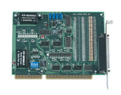
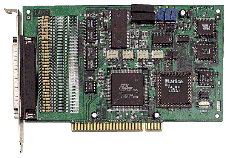
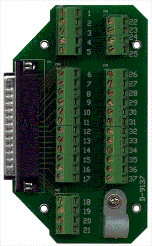
Comprehensive Product Summary – ADLINK NuDAQ® ACLD‑9881 Termination Board
### 1. Product Overview
Product Name: ACLD‑9881
Article Number: ACLD‑9881
Series: NuDAQ® ACLD Series Termination Boards
Manufacturer: ADLINK Technology Inc.
Associated Cable: ACL‑10137‑1 (included)
Compatible Devices: PCI‑9113A, ACL‑8113A data acquisition cards
Product Type: Industrial termination and signal conditioning panel for low‑pass filter and analog input interfacing
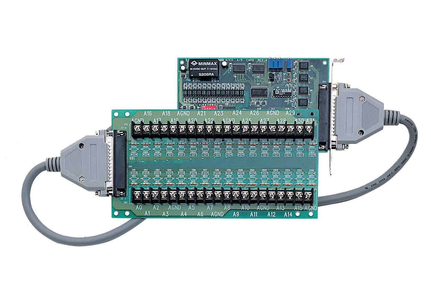
The ADLINK NuDAQ® ACLD‑9881 is a dedicated termination and signal conditioning board designed to provide a convenient, reliable interface between ADLINK’s PCI‑9113A or ACL‑8113A data acquisition (DAQ) cards and external analog signal sources. It features a 37‑pin D‑sub connector, screw terminal blocks, and onboard RC filter networks for each of its 32 single‑ended analog input channels. The ACLD‑9881 simplifies wiring, enhances signal integrity, and allows users to implement custom low‑pass filters or attenuation networks directly on the board.
### 2. Key Features
- Comprehensive Signal Termination:
Provides 32 single‑ended analog input channels accessible via screw terminals and a 37‑pin D‑sub connector.
- Integrated RC Filter Network:
Each channel includes provisions for user‑configurable resistor (R) and capacitor (C) components, enabling low‑pass filtering, voltage attenuation, or current‑to‑voltage conversion.
- Flexible Signal Conditioning:
Supports installation of custom RC components for noise suppression, bandwidth limitation, or signal scaling.
- Universal Connectivity:
Equipped with a 37‑pin D‑sub female connector compatible with ADLINK’s ACL‑8113A and PCI‑9113A DAQ cards via the included ACL‑10137‑1 cable.
- Industrial‑Grade Screw Terminals:
Heavy‑duty screw clamp terminals ensure secure, vibration‑resistant connections suitable for laboratory and industrial environments.
- Included Accessories:
Ships with a 1‑meter ACL‑10137‑1 cable and nylon standoffs for table‑top or panel mounting.
- Low‑Cost, High‑Reliability Design:
Provides a cost‑effective solution for analog signal interfacing, filtering, and conditioning without requiring external circuitry.
- Ground Reference Flexibility:
Allows grounding of input channels by modifying resistor configuration (e.g., cutting RA and setting RB = 0 Ω) for offset calibration or current sensing.
- Compact Form Factor:
Board dimensions of approximately 221 mm × 105 mm allow easy integration into control panels or test benches.
### 3. Technical Specifications
| Parameter | Specification |
|----------------|-------------------|
| Model | ACLD‑9881 |
| Series | NuDAQ® ACLD Termination Boards |
| Manufacturer | ADLINK Technology Inc. |
| Connector Type | 37‑pin D‑sub female |
| Number of Channels | 32 single‑ended analog input channels |
| Signal Conditioning | RC filter network per channel (user‑installable resistors and capacitors) |
| Input Configuration | Single‑ended (common ground reference) |
| Compatible DAQ Cards | PCI‑9113A, ACL‑8113A |
| Included Cable | ACL‑10137‑1, 1 m length, DB‑37 male‑to‑male |
| Terminal Type | Screw clamp terminal blocks, 2 × 20 configuration |
| Board Dimensions | 221 mm × 105 mm |
| Mounting Options | Table‑top or panel mounting with nylon standoffs |
| Material | FR‑4 PCB with industrial‑grade terminal blocks |
| Operating Voltage Range | Determined by DAQ card input range (typically ±10 V) |
| Filter Components | User‑defined R and C values per channel |
| Ground Reference Points | Multiple AGND pins (CN1‑9, 10, 19, 28, 29) |
| Weight | Approx. 0.3 kg (board only) |
| Operating Environment | Laboratory or industrial control systems |
| Compliance | CE/EMC compliant (per ADLINK NuDAQ series standards) |
### 4. Functionality
The ACLD‑9881 serves as a termination and conditioning interface between analog signal sources and ADLINK’s PCI‑9113A or ACL‑8113A DAQ cards. It provides a structured wiring platform that simplifies connection, filtering, and calibration of analog inputs.
Working Principle:
- Each of the 32 channels is routed through a resistor‑capacitor (RC) network.
- Users can populate the resistor (RA, RB) and capacitor (C) pads to create low‑pass filters, voltage dividers, or current‑to‑voltage converters.
- The RC network attenuates high‑frequency noise and stabilizes analog signals before they reach the DAQ card’s input stage.
- The board’s ground reference can be configured by modifying resistor links, allowing calibration or offset compensation.
Typical Use Cases:
- Analog signal acquisition from sensors, transducers, or instrumentation amplifiers.
- Implementation of low‑pass filters to suppress high‑frequency noise in measurement systems.
- Voltage attenuation for high‑amplitude signals to match DAQ input ranges.
- Current‑to‑voltage conversion for 4–20 mA or 0–20 mA current loop sensors.
- Laboratory test setups requiring flexible signal conditioning.
- Industrial process monitoring and control systems.
Compatibility:
- Fully compatible with ADLINK PCI‑9113A and ACL‑8113A analog input cards.
- Connects via the included ACL‑10137‑1 DB‑37 cable.
- Can be used with other NuDAQ‑series boards that share the same 37‑pin pinout.
### 5. Components & Accessories
Included Items:
1. ACLD‑9881 Termination Board – fully assembled PCB with screw terminals and DB‑37 connector.
2. ACL‑10137‑1 Cable – 1‑meter shielded DB‑37 male‑to‑male cable for connection to DAQ card.
3. Nylon Standoffs – for secure table‑top or panel mounting.
4. User Documentation – NuDAQ ACLD Series User’s Guide (Rev. 2.40, June 7 2000).
Optional Accessories:
- Additional ACL‑10137‑1 or equivalent DB‑37 cables for extended installations.
- Custom resistor and capacitor components for RC filter configuration.
- Shielded enclosures or DIN‑rail mounting kits for industrial environments.
Connectors:
- CN1: 37‑pin D‑sub female connector (primary interface to DAQ card).
- Screw Terminals: 2 × 20 terminal blocks for field wiring of analog inputs and ground connections.
### 6. Installation & Setup
Requirements:
- Compatible ADLINK DAQ card (PCI‑9113A or ACL‑8113A).
- Available DB‑37 interface port on the DAQ card.
- Proper grounding and shielding for analog signal integrity.
Installation Steps:
1. Unpack and Inspect: Verify that the ACLD‑9881 board, ACL‑10137‑1 cable, and standoffs are included and undamaged.
2. Mounting: Install the board on a flat surface or panel using the provided nylon standoffs.
3. Connection to DAQ Card:
- Connect the ACL‑10137‑1 cable between the DAQ card’s DB‑37 connector and the ACLD‑9881’s CN1 port.
- Ensure secure fastening of the D‑sub connectors.
4. Field Wiring:
- Connect analog input signals to the corresponding screw terminals (A0–A31).
- Connect all signal grounds to the AGND terminals (CN1‑9, 10, 19, 28, 29).
5. Optional RC Configuration:
- Populate RA, RB, and C component pads per channel to implement desired filtering or attenuation.
- Example: For a 1.6 kHz low‑pass filter, use R = 10 kΩ and C = 0.01 µF.
6. Verification:
- Power on the DAQ system and verify signal integrity through the acquisition software.
- Adjust component values or grounding as needed.
Configuration Notes:
- The board supports single‑ended input configuration only.
- Ensure that all grounds are common to prevent measurement errors.
- Avoid simultaneous use of multiple ground paths that could create loops.
### 7. Performance & Capabilities
Signal Conditioning Performance:
- Low‑Pass Filtering:
Each channel can be configured for a specific cutoff frequency using the formula:
*f₃dB = 1 / (2π R × C)*
Example: R = 10 kΩ, C = 0.01 µF → f₃dB ≈ 1.6 kHz.
- Voltage Attenuation:
Configurable voltage divider using RA and RB:
*Vout = Vin × (RB / (RA + RB))*
Example: RA = 9 kΩ, RB = 1 kΩ → 10:1 attenuation.
- Current‑to‑Voltage Conversion:
For 0–20 mA current loops, set R = 250 Ω → 0–5 V output range.
Electrical Characteristics:
- Input Impedance: Determined by installed resistor network (typically ≥ 10 kΩ).
- Isolation: Ground‑referenced single‑ended configuration (no channel‑to‑channel isolation).
- Noise Reduction: RC filtering reduces high‑frequency interference and improves measurement stability.
- Signal Range: Matches DAQ card input range (typically ±10 V or 0–10 V).
- Temperature Stability: Passive components ensure minimal drift; dependent on resistor/capacitor tolerances.
Limitations:
- Single‑ended only (no differential input support).
- No active amplification or isolation circuitry.
- Filtering and attenuation depend on user‑installed components.
- Designed for low‑frequency analog signals (typically < 10 kHz bandwidth).
### 8. Standards & Compliance
The ACLD‑9881 is part of ADLINK’s NuDAQ® family of termination and conditioning boards, designed to meet industrial and laboratory standards for data acquisition interfacing.
Compliance and Standards:
- Electrical Safety: Designed in accordance with IEC/EN 61010‑1 for measurement and control equipment.
- EMC Compliance: Meets CE and FCC Class A requirements when used with shielded cables.
- RoHS Compliance: Manufactured using lead‑free processes (per ADLINK environmental policy).
- Quality Assurance: Produced under ISO 9001‑certified manufacturing processes.
- Trademark: NuDAQ® is a registered trademark of ADLINK Technology Inc.
Regulatory Notes:
- The product documentation specifies that specifications are subject to change without notice to improve reliability and performance.
- ADLINK disclaims liability for consequential damages arising from misuse or modification.
### 9. Additional Information
Warranty:
- Duration: 1 year from the confirmed date of purchase.
- Coverage: Free from defects in materials and workmanship under normal use.
- Exclusions:
- Damage due to misuse, modification, or operation beyond specifications.
- Units with removed or altered serial numbers.
- Repairs performed outside ADLINK facilities without authorization.
- Remedy: Repair or replacement at ADLINK’s discretion.
- Return Policy: Equipment must be securely packaged and shipped prepaid with proof of purchase.
Technical Support & Service:
- Manufacturer Contact:
ADLINK Technology Inc.
9F, No. 166, Jian Yi Road, Chungho City, Taipei 235, Taiwan, R.O.C.
Tel: +886‑2‑8226‑5877 Fax: +886‑2‑8226‑5717
Website: [www.adlink.com.tw](http://www.adlink.com.tw)
Email: service@adlink.com.tw (Sales & Service)
Technical Support: nudaq@adlink.com.tw
Maintenance:
- Periodically inspect screw terminals for secure connections.
- Verify integrity of RC components if installed.
- Keep the board free from dust and moisture.
- Avoid exposure to excessive vibration or temperature extremes.
Software & Updates:
- The ACLD‑9881 itself requires no firmware or software.
- Configuration and calibration are managed through the connected DAQ card’s driver and software suite (e.g., ADLINK NuDAQ driver package).
- Updated manuals and driver support are available from ADLINK’s website.
Documentation Reference:
- *NuDAQ® ACLD Series Termination Boards User’s Guide*, Manual Rev. 2.40, June 7 2000, Part No. 50‑14006‑200.
### Summary
The ADLINK NuDAQ® ACLD‑9881 is a robust, flexible termination and signal conditioning board engineered for analog data acquisition systems. Its 37‑pin D‑sub interface and 32 single‑ended channels provide a direct, organized connection between field signals and ADLINK’s PCI‑9113A or ACL‑8113A DAQ cards. By integrating user‑configurable RC networks, the ACLD‑9881 enables precise low‑pass filtering, voltage attenuation, and current‑to‑voltage conversion without external circuitry. The inclusion of industrial screw terminals, a shielded cable, and mounting accessories ensures reliable operation in both laboratory and industrial environments. With ADLINK’s one‑year warranty and comprehensive technical support, the ACLD‑9881 offers a dependable, cost‑effective solution for analog signal interfacing and conditioning in data acquisition applications.


 SUCHEN SIE DIE PASSENDE
 ACLD.pdf
Manual
ACLD.pdf
Manual
 ACLD Series.PDF
Manual
ACLD Series.PDF
Manual