SUCHEN SIE DIE PASSENDE
INDUSTRIELLE LÖSUNG?
Entdecken Sie Embedded-, Kommunikations- und Automatisierungslösungen für Ihre Anwendung.
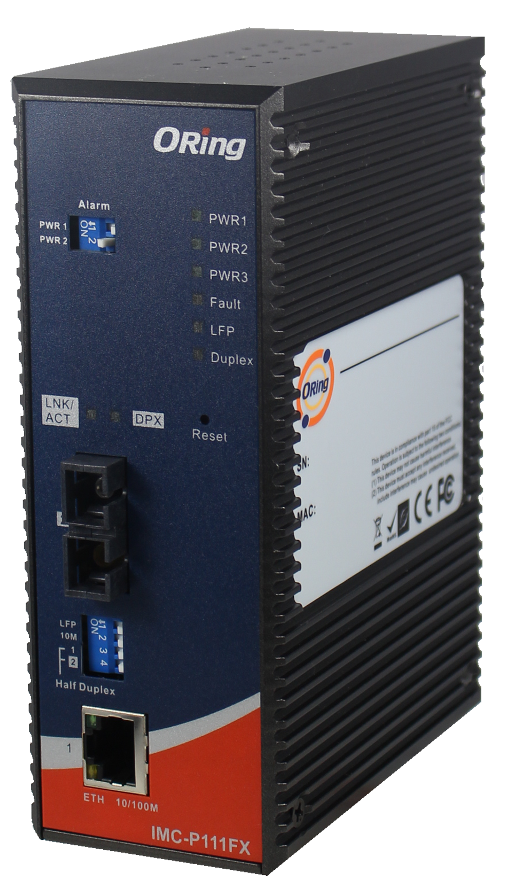
• Designed for critical infrastructure: Fully compliant with IEC 61850‑3 and IEEE 1613 standards for power substations and electrical grid applications.
• Supports EN50155‑compliant environments, suitable for rolling stock use.
• Provides conversion between 1×10/100Base‑T(X) auto‑negotiation port and 1×100Base‑FX fiber port.
• Single‑mode fiber (SS type) with SC connector, supporting long‑distance links up to 30 km at 1310 nm.
• Wide operating temperature range: –40°C to 85°C for HV model.
• Dual 100–240VAC power inputs for high‑voltage industrial redundancy.
• LFP (Link Fault Pass‑through) support for intelligent link status forwarding.
• Auto MDI/MDIX detection eliminates need for crossover cables.
• Supports full/half‑duplex modes and store‑and‑forward processing.
• Provides hardware DIP‑switch configuration for speed, duplex, LFP function, and fiber duplex selection.
• High‑reliability IP‑30 metal housing.
• Supports DIN‑rail and wall‑mount installation.
• Relay output for power failure alarms (PWR‑1 or PWR‑2 loss).
• Extensive EMC, EMI, shock, vibration, and free‑fall compliance.
• Supports EN50155‑compliant environments, suitable for rolling stock use.
• Provides conversion between 1×10/100Base‑T(X) auto‑negotiation port and 1×100Base‑FX fiber port.
• Single‑mode fiber (SS type) with SC connector, supporting long‑distance links up to 30 km at 1310 nm.
• Wide operating temperature range: –40°C to 85°C for HV model.
• Dual 100–240VAC power inputs for high‑voltage industrial redundancy.
• LFP (Link Fault Pass‑through) support for intelligent link status forwarding.
• Auto MDI/MDIX detection eliminates need for crossover cables.
• Supports full/half‑duplex modes and store‑and‑forward processing.
• Provides hardware DIP‑switch configuration for speed, duplex, LFP function, and fiber duplex selection.
• High‑reliability IP‑30 metal housing.
• Supports DIN‑rail and wall‑mount installation.
• Relay output for power failure alarms (PWR‑1 or PWR‑2 loss).
• Extensive EMC, EMI, shock, vibration, and free‑fall compliance.
Below is a high‑detail, comprehensive product summary for the IMC‑P111FX‑SS‑SC‑HV industrial media converter. The summary follows your requested structure, preserves all technical details, and is optimized for technical search and engineering documentation.
--------------------------------------------------------------------
1. Product Overview
• Product Name: Industrial Media Converter IEC‑61850 100TX‑to‑100FX SS 230V
• Model: IMC‑P111FX‑SS‑SC‑HV
• Series: IMC‑P111 Series
• Article Number: IMC‑P111FX‑SS‑SC‑HV
• Manufacturer: ORing Industrial Networking Corp.
• Product Type: Industrial-grade Ethernet‑to‑Fiber Media Converter (10/100Base‑T(X) to 100Base‑FX)
• Description: Single‑mode fiber media converter designed for power substations, smart grid, and rolling stock applications, supporting IEC 61850‑3 and IEEE 1613 environments, with dual 100–240VAC high‑voltage power inputs.
--------------------------------------------------------------------
2. Key Features
• Designed for critical infrastructure: Fully compliant with IEC 61850‑3 and IEEE 1613 standards for power substations and electrical grid applications.
• Supports EN50155‑compliant environments, suitable for rolling stock use.
• Provides conversion between 1×10/100Base‑T(X) auto‑negotiation port and 1×100Base‑FX fiber port.
• Single‑mode fiber (SS type) with SC connector, supporting long‑distance links up to 30 km at 1310 nm.
• Wide operating temperature range: –40°C to 85°C for HV model.
• Dual 100–240VAC power inputs for high‑voltage industrial redundancy.
• LFP (Link Fault Pass‑through) support for intelligent link status forwarding.
• Auto MDI/MDIX detection eliminates need for crossover cables.
• Supports full/half‑duplex modes and store‑and‑forward processing.
• Provides hardware DIP‑switch configuration for speed, duplex, LFP function, and fiber duplex selection.
• High‑reliability IP‑30 metal housing.
• Supports DIN‑rail and wall‑mount installation.
• Relay output for power failure alarms (PWR‑1 or PWR‑2 loss).
• Extensive EMC, EMI, shock, vibration, and free‑fall compliance.
--------------------------------------------------------------------
3. Technical Specifications
Physical & Mechanical
• Dimensions:
– Width: 54.1 mm
– Depth: 106.1 mm
– Height: 145.4 mm
• Weight (HV model): 802 g
• Housing: Metal, IP‑30 rated
• Mounting: DIN‑rail and wall‑mount
• Enclosure Type: Industrial‑grade rigid housing
Ethernet Interface
• 1×10/100Base‑T(X) RJ45 port
• Auto‑Negotiation: Supported
• Auto‑MDI/MDIX: Supported
• Supported Standards:
– IEEE 802.3 (10Base‑T)
– IEEE 802.3u (100Base‑TX / 100Base‑FX)
– IEEE 802.3x (Flow Control)
Fiber Interface (Single‑Mode, SS)
• Fiber Type: 9/125 µm single‑mode
• Connector: SC
• Standard: 100Base‑FX
• Wavelength: 1310 nm
• Typical Distance: 30 km
• Optical Power:
– Max Output: –8 dBm
– Min Output: –15 dBm
– Max Input (Saturation): 0 dBm
– Min Input (Sensitivity): –34 dBm
• Link Budget: 19 dB
Environmental
• Operating Temperature: –40°C to 70°C (general), –40°C to 85°C supported as described in product summary
• Storage Temperature: –40°C to 85°C
• Humidity: 5%–95% non‑condensing
Power
• Power Inputs (HV Model):
– Dual 100–240VAC inputs via 8‑pin terminal block
• Power Consumption:
– 100VAC: approx. 4.2–4.8 W
– 240VAC: approx. 5.2–5.8 W
• Protections:
– Overload current protection
– Reverse polarity protection (terminal block)
• Relay Output:
– Power-failure alarm relay output
LED Indicators
• Power LEDs (HV Model): 2 green LEDs (PWR‑1, PWR‑2)
• RJ45 Port:
– Green: Link/Activity
– Amber: 100 Mbps speed indicator
– Duplex indicator (Full/Half)
• Fiber Port:
– Green: Link/Activity
– Amber: Duplex indicator
• LFP Indicator: Amber
• Fault Indicator: Amber
Regulatory Approvals
• EMI: FCC Part 15, CISPR EN55022 Class A
• EMS:
– EN61000‑4‑2 (ESD)
– EN61000‑4‑3 (RS)
– EN61000‑4‑4 (EFT)
– EN61000‑4‑5 (Surge)
– EN61000‑4‑6 (CS)
– EN61000‑4‑8
– EN61000‑4‑11
• Shock: IEC 60068‑2‑27
• Free Fall: IEC 60068‑2‑32
• Vibration: IEC 60068‑2‑6
• Safety: EN60950‑1
--------------------------------------------------------------------
4. Functionality
Core Function
• Converts electrical Ethernet signals (10/100Base‑T(X)) to optical fiber (100Base‑FX single‑mode).
• Enables extended communication ranges over fiber up to 30 km.
• Designed for harsh environmental and electrically noisy industrial settings such as substations and rail systems.
LFP (Link Fault Pass‑Through)
• When one communication side fails, the converter forces the corresponding link to shut down.
• Enables network management systems or application software to detect actual link failure.
• Configurable via DIP‑switch.
Operating Modes
• Auto‑negotiation or forced speed (10 Mbps) selection for copper port
• Full/half‑duplex configurable for Ethernet and fiber
• Store‑and‑forward switching ensures optimized packet integrity
Use Cases
• Power substations following IEC 61850‑3
• Smart grid communication networks
• Railway and rolling stock networking
• Long‑distance industrial Ethernet expansion
• Fiber‑based noise‑immune backbones
• Environments requiring redundant high‑voltage power input
Compatibility
• Compatible with standard 100Base‑FX single‑mode fiber networks
• Works with SC‑terminated fiber infrastructure
• Supports IEEE Ethernet protocols for interoperability with switches, routers, HMIs, and PLCs
--------------------------------------------------------------------
5. Components & Accessories
Included Components
• Main unit: IMC‑P111FX‑SS‑SC‑HV media converter
• 7‑pin or 8‑pin terminal block (HV version uses 8‑pin)
• Dust covers for RJ‑45 port
• Dust covers for fiber port
• DIN‑rail kit (25 mm rail kit)
• Wall‑mounting brackets
• Flat-head screws (M3 × 5 mm)
• Quick Installation Guide
• Power cable (for HV model)
Connectivity Ports
• 1×RJ45 10/100Base‑T(X)
• 1×SC single‑mode fiber 100Base‑FX
• Terminal block for dual AC power inputs
• Relay output terminals
• Reset button
Optional Add-ons
• Additional DIN‑rail adapters
• Industrial-grade fiber patch cords
• Single-mode SC optical fiber accessories
• Redundant power supply modules (external)
--------------------------------------------------------------------
6. Installation & Setup
Installation Options
• DIN‑Rail mounting: Standard 25 mm rail support
• Wall‑mounting: Included mounting plates and screws
Power Setup
• Connect dual AC power inputs (100–240VAC) to the 8‑pin terminal block.
• Ensure proper grounding via Frame Ground terminal.
• Relay output can be wired for alarms and monitoring systems.
DIP‑Switch Configuration
DIP Switch for Mode Selection:
• DIP‑1: LFP Mode
– ON: Enable
– OFF: Disable
• DIP‑2: Ethernet Speed
– ON: Force 10 Mbps
– OFF: Auto‑negotiation (10/100 Mbps)
• DIP‑3: Ethernet Duplex
– ON: Half‑duplex
– OFF: Full/Half auto‑negotiation
• DIP‑4: Fiber Duplex
– ON: Half‑duplex
– OFF: Full‑duplex
DIP Switch for Alarm (Power Side)
• Alarm relay for PWR‑1 or PWR‑2 failure
• DIP combinations allow enabling/disabling PWR‑1 or PWR‑2 alarm
General Setup Steps
• Mount device (DIN‑rail or wall‑mount).
• Connect fiber cable to SC fiber port.
• Connect Ethernet cable to RJ45 port.
• Wire power inputs and optional relay output.
• Configure DIP‑switches according to network requirements.
• Verify LEDs for link/activity and power state.
--------------------------------------------------------------------
7. Performance & Capabilities
Network Performance
• Conversion between copper and fiber at full 100 Mbps bandwidth
• Store‑and‑forward minimizes packet loss
• Supports long‑distance fiber up to 30 km
• Link budget of 19 dB ensures compatibility with long‑reach fiber networks
• Full/half‑duplex flexibility optimizes performance based on network design
Speed & Throughput
• Ethernet port supports 10/100 Mbps
• Fiber port fixed at 100 Mbps FX
• Low latency switching suitable for automation protocols and substation networks
Electrical Performance
• Supports dual AC inputs for redundancy
• Designed to withstand harsh electrical environments (surges, ESD, EFT)
Environmental Performance
• Reliable operation from –40°C to 85°C
• Tested under vibration, shock, and free-fall conditions according to IEC 60068 standards
Limitations
• Only one copper and one fiber port
• Fixed fiber standard: 100Base‑FX (no Gigabit support)
• SFP not supported in this model (fixed SC type)
--------------------------------------------------------------------
8. Standards & Compliance
Harsh Environment & Industry Standards
• IEC 61850‑3: Power substation communication
• IEEE 1613: Electric power utility equipment
• EN50155 compliance for rolling stock (environmental considerations)
Ethernet Protocol Standards
• IEEE 802.3, 802.3u, 802.3x
Safety and Environmental
• EN60950‑1 safety compliance
• Wide temperature and humidity certifications
• EMC/EMI compliance with multiple EN61000‑4 standards
• Industrial-grade shock, vibration, and free fall resistance:
– IEC 60068‑2‑27
– IEC 60068‑2‑6
– IEC 60068‑2‑32
--------------------------------------------------------------------
9. Additional Information
Warranty
• 5‑year standard manufacturer warranty
Support & Maintenance
• Technical support via ORing Industrial Networking Corp.
• Firmware updates available for series products (if applicable)
• Routine maintenance includes checking power wiring, cleaning fiber connectors, and ensuring stable DIN‑rail or wall‑mount installation.
Documentation
• Quick Installation Guide included
• Full user manual available from ORing’s website
Manufacturer Contact
• Website: www.oring-networking.com
• Email: support@oring-networking.com
• Tel: +886‑2‑2218‑1066
--------------------------------------------------------------------
If you'd like, I can also produce:
• A shorter summary
• A marketing‑optimized version
• A comparison with other IMC‑P111 variants (LV, MM, SFP versions)
• A datasheet‑formatted version
--------------------------------------------------------------------
1. Product Overview
• Product Name: Industrial Media Converter IEC‑61850 100TX‑to‑100FX SS 230V
• Model: IMC‑P111FX‑SS‑SC‑HV
• Series: IMC‑P111 Series
• Article Number: IMC‑P111FX‑SS‑SC‑HV
• Manufacturer: ORing Industrial Networking Corp.
• Product Type: Industrial-grade Ethernet‑to‑Fiber Media Converter (10/100Base‑T(X) to 100Base‑FX)
• Description: Single‑mode fiber media converter designed for power substations, smart grid, and rolling stock applications, supporting IEC 61850‑3 and IEEE 1613 environments, with dual 100–240VAC high‑voltage power inputs.
--------------------------------------------------------------------
2. Key Features
• Designed for critical infrastructure: Fully compliant with IEC 61850‑3 and IEEE 1613 standards for power substations and electrical grid applications.
• Supports EN50155‑compliant environments, suitable for rolling stock use.
• Provides conversion between 1×10/100Base‑T(X) auto‑negotiation port and 1×100Base‑FX fiber port.
• Single‑mode fiber (SS type) with SC connector, supporting long‑distance links up to 30 km at 1310 nm.
• Wide operating temperature range: –40°C to 85°C for HV model.
• Dual 100–240VAC power inputs for high‑voltage industrial redundancy.
• LFP (Link Fault Pass‑through) support for intelligent link status forwarding.
• Auto MDI/MDIX detection eliminates need for crossover cables.
• Supports full/half‑duplex modes and store‑and‑forward processing.
• Provides hardware DIP‑switch configuration for speed, duplex, LFP function, and fiber duplex selection.
• High‑reliability IP‑30 metal housing.
• Supports DIN‑rail and wall‑mount installation.
• Relay output for power failure alarms (PWR‑1 or PWR‑2 loss).
• Extensive EMC, EMI, shock, vibration, and free‑fall compliance.
--------------------------------------------------------------------
3. Technical Specifications
Physical & Mechanical
• Dimensions:
– Width: 54.1 mm
– Depth: 106.1 mm
– Height: 145.4 mm
• Weight (HV model): 802 g
• Housing: Metal, IP‑30 rated
• Mounting: DIN‑rail and wall‑mount
• Enclosure Type: Industrial‑grade rigid housing
Ethernet Interface
• 1×10/100Base‑T(X) RJ45 port
• Auto‑Negotiation: Supported
• Auto‑MDI/MDIX: Supported
• Supported Standards:
– IEEE 802.3 (10Base‑T)
– IEEE 802.3u (100Base‑TX / 100Base‑FX)
– IEEE 802.3x (Flow Control)
Fiber Interface (Single‑Mode, SS)
• Fiber Type: 9/125 µm single‑mode
• Connector: SC
• Standard: 100Base‑FX
• Wavelength: 1310 nm
• Typical Distance: 30 km
• Optical Power:
– Max Output: –8 dBm
– Min Output: –15 dBm
– Max Input (Saturation): 0 dBm
– Min Input (Sensitivity): –34 dBm
• Link Budget: 19 dB
Environmental
• Operating Temperature: –40°C to 70°C (general), –40°C to 85°C supported as described in product summary
• Storage Temperature: –40°C to 85°C
• Humidity: 5%–95% non‑condensing
Power
• Power Inputs (HV Model):
– Dual 100–240VAC inputs via 8‑pin terminal block
• Power Consumption:
– 100VAC: approx. 4.2–4.8 W
– 240VAC: approx. 5.2–5.8 W
• Protections:
– Overload current protection
– Reverse polarity protection (terminal block)
• Relay Output:
– Power-failure alarm relay output
LED Indicators
• Power LEDs (HV Model): 2 green LEDs (PWR‑1, PWR‑2)
• RJ45 Port:
– Green: Link/Activity
– Amber: 100 Mbps speed indicator
– Duplex indicator (Full/Half)
• Fiber Port:
– Green: Link/Activity
– Amber: Duplex indicator
• LFP Indicator: Amber
• Fault Indicator: Amber
Regulatory Approvals
• EMI: FCC Part 15, CISPR EN55022 Class A
• EMS:
– EN61000‑4‑2 (ESD)
– EN61000‑4‑3 (RS)
– EN61000‑4‑4 (EFT)
– EN61000‑4‑5 (Surge)
– EN61000‑4‑6 (CS)
– EN61000‑4‑8
– EN61000‑4‑11
• Shock: IEC 60068‑2‑27
• Free Fall: IEC 60068‑2‑32
• Vibration: IEC 60068‑2‑6
• Safety: EN60950‑1
--------------------------------------------------------------------
4. Functionality
Core Function
• Converts electrical Ethernet signals (10/100Base‑T(X)) to optical fiber (100Base‑FX single‑mode).
• Enables extended communication ranges over fiber up to 30 km.
• Designed for harsh environmental and electrically noisy industrial settings such as substations and rail systems.
LFP (Link Fault Pass‑Through)
• When one communication side fails, the converter forces the corresponding link to shut down.
• Enables network management systems or application software to detect actual link failure.
• Configurable via DIP‑switch.
Operating Modes
• Auto‑negotiation or forced speed (10 Mbps) selection for copper port
• Full/half‑duplex configurable for Ethernet and fiber
• Store‑and‑forward switching ensures optimized packet integrity
Use Cases
• Power substations following IEC 61850‑3
• Smart grid communication networks
• Railway and rolling stock networking
• Long‑distance industrial Ethernet expansion
• Fiber‑based noise‑immune backbones
• Environments requiring redundant high‑voltage power input
Compatibility
• Compatible with standard 100Base‑FX single‑mode fiber networks
• Works with SC‑terminated fiber infrastructure
• Supports IEEE Ethernet protocols for interoperability with switches, routers, HMIs, and PLCs
--------------------------------------------------------------------
5. Components & Accessories
Included Components
• Main unit: IMC‑P111FX‑SS‑SC‑HV media converter
• 7‑pin or 8‑pin terminal block (HV version uses 8‑pin)
• Dust covers for RJ‑45 port
• Dust covers for fiber port
• DIN‑rail kit (25 mm rail kit)
• Wall‑mounting brackets
• Flat-head screws (M3 × 5 mm)
• Quick Installation Guide
• Power cable (for HV model)
Connectivity Ports
• 1×RJ45 10/100Base‑T(X)
• 1×SC single‑mode fiber 100Base‑FX
• Terminal block for dual AC power inputs
• Relay output terminals
• Reset button
Optional Add-ons
• Additional DIN‑rail adapters
• Industrial-grade fiber patch cords
• Single-mode SC optical fiber accessories
• Redundant power supply modules (external)
--------------------------------------------------------------------
6. Installation & Setup
Installation Options
• DIN‑Rail mounting: Standard 25 mm rail support
• Wall‑mounting: Included mounting plates and screws
Power Setup
• Connect dual AC power inputs (100–240VAC) to the 8‑pin terminal block.
• Ensure proper grounding via Frame Ground terminal.
• Relay output can be wired for alarms and monitoring systems.
DIP‑Switch Configuration
DIP Switch for Mode Selection:
• DIP‑1: LFP Mode
– ON: Enable
– OFF: Disable
• DIP‑2: Ethernet Speed
– ON: Force 10 Mbps
– OFF: Auto‑negotiation (10/100 Mbps)
• DIP‑3: Ethernet Duplex
– ON: Half‑duplex
– OFF: Full/Half auto‑negotiation
• DIP‑4: Fiber Duplex
– ON: Half‑duplex
– OFF: Full‑duplex
DIP Switch for Alarm (Power Side)
• Alarm relay for PWR‑1 or PWR‑2 failure
• DIP combinations allow enabling/disabling PWR‑1 or PWR‑2 alarm
General Setup Steps
• Mount device (DIN‑rail or wall‑mount).
• Connect fiber cable to SC fiber port.
• Connect Ethernet cable to RJ45 port.
• Wire power inputs and optional relay output.
• Configure DIP‑switches according to network requirements.
• Verify LEDs for link/activity and power state.
--------------------------------------------------------------------
7. Performance & Capabilities
Network Performance
• Conversion between copper and fiber at full 100 Mbps bandwidth
• Store‑and‑forward minimizes packet loss
• Supports long‑distance fiber up to 30 km
• Link budget of 19 dB ensures compatibility with long‑reach fiber networks
• Full/half‑duplex flexibility optimizes performance based on network design
Speed & Throughput
• Ethernet port supports 10/100 Mbps
• Fiber port fixed at 100 Mbps FX
• Low latency switching suitable for automation protocols and substation networks
Electrical Performance
• Supports dual AC inputs for redundancy
• Designed to withstand harsh electrical environments (surges, ESD, EFT)
Environmental Performance
• Reliable operation from –40°C to 85°C
• Tested under vibration, shock, and free-fall conditions according to IEC 60068 standards
Limitations
• Only one copper and one fiber port
• Fixed fiber standard: 100Base‑FX (no Gigabit support)
• SFP not supported in this model (fixed SC type)
--------------------------------------------------------------------
8. Standards & Compliance
Harsh Environment & Industry Standards
• IEC 61850‑3: Power substation communication
• IEEE 1613: Electric power utility equipment
• EN50155 compliance for rolling stock (environmental considerations)
Ethernet Protocol Standards
• IEEE 802.3, 802.3u, 802.3x
Safety and Environmental
• EN60950‑1 safety compliance
• Wide temperature and humidity certifications
• EMC/EMI compliance with multiple EN61000‑4 standards
• Industrial-grade shock, vibration, and free fall resistance:
– IEC 60068‑2‑27
– IEC 60068‑2‑6
– IEC 60068‑2‑32
--------------------------------------------------------------------
9. Additional Information
Warranty
• 5‑year standard manufacturer warranty
Support & Maintenance
• Technical support via ORing Industrial Networking Corp.
• Firmware updates available for series products (if applicable)
• Routine maintenance includes checking power wiring, cleaning fiber connectors, and ensuring stable DIN‑rail or wall‑mount installation.
Documentation
• Quick Installation Guide included
• Full user manual available from ORing’s website
Manufacturer Contact
• Website: www.oring-networking.com
• Email: support@oring-networking.com
• Tel: +886‑2‑2218‑1066
--------------------------------------------------------------------
If you'd like, I can also produce:
• A shorter summary
• A marketing‑optimized version
• A comparison with other IMC‑P111 variants (LV, MM, SFP versions)
• A datasheet‑formatted version
-
 Datasheet_IMC-P111FX_V1.0_HQ.pdf
PDF Catalog
Datasheet_IMC-P111FX_V1.0_HQ.pdf
PDF Catalog
-
 DataSheet_IMC-P111FX_P111P_Series_V2.0.pdf
PDF Catalog
DataSheet_IMC-P111FX_P111P_Series_V2.0.pdf
PDF Catalog

Kein Zubehör vorhanden.