SUCHEN SIE DIE PASSENDE
INDUSTRIELLE LÖSUNG?
Entdecken Sie Embedded-, Kommunikations- und Automatisierungslösungen für Ihre Anwendung.
• Fully compliant with IEC 61850-3 and IEEE 1613 standards for power substation and smart grid infrastructure
• EN50155-compliant for railway and rolling-stock applications
• Extends Ethernet communication via 100Base-FX single-mode fiber up to 30 km at 1310 nm
• Rugged M12 D-coded Ethernet connector ensures vibration- and shock-resistant connections
• Operating temperature range from -40 to 85 degrees Celsius
• High-voltage dual AC power input: 100–240VAC
• Supports auto-negotiation and auto-MDI/MDI-X on the LAN port
• Selectable DIP-switch configurations for LFP, speed, duplex modes, and power failure alarms
• LFP (Link Fault Pass-through) support for improved network diagnostic behavior
• Store-and-forward switching architecture
• IP-30 rated metal enclosure
• Relay output for power-failure alarm event notification
• Supports both DIN-rail and wall-mount installation
• LED indicators for power, link/activity, duplex, fiber status, LFP, and fault conditions
• Compatible with optional SFP modules (for P model), optional external power supplies, and various regional high-voltage versions
• EN50155-compliant for railway and rolling-stock applications
• Extends Ethernet communication via 100Base-FX single-mode fiber up to 30 km at 1310 nm
• Rugged M12 D-coded Ethernet connector ensures vibration- and shock-resistant connections
• Operating temperature range from -40 to 85 degrees Celsius
• High-voltage dual AC power input: 100–240VAC
• Supports auto-negotiation and auto-MDI/MDI-X on the LAN port
• Selectable DIP-switch configurations for LFP, speed, duplex modes, and power failure alarms
• LFP (Link Fault Pass-through) support for improved network diagnostic behavior
• Store-and-forward switching architecture
• IP-30 rated metal enclosure
• Relay output for power-failure alarm event notification
• Supports both DIN-rail and wall-mount installation
• LED indicators for power, link/activity, duplex, fiber status, LFP, and fault conditions
• Compatible with optional SFP modules (for P model), optional external power supplies, and various regional high-voltage versions
Below is a comprehensive, detailed product summary for the IMC-P111FX-SS-SC-M12-HV based strictly on the supplied content. Formatting avoids special characters and stays machine‑parsable.
--------------------------------------------------------------------
1. Product Overview
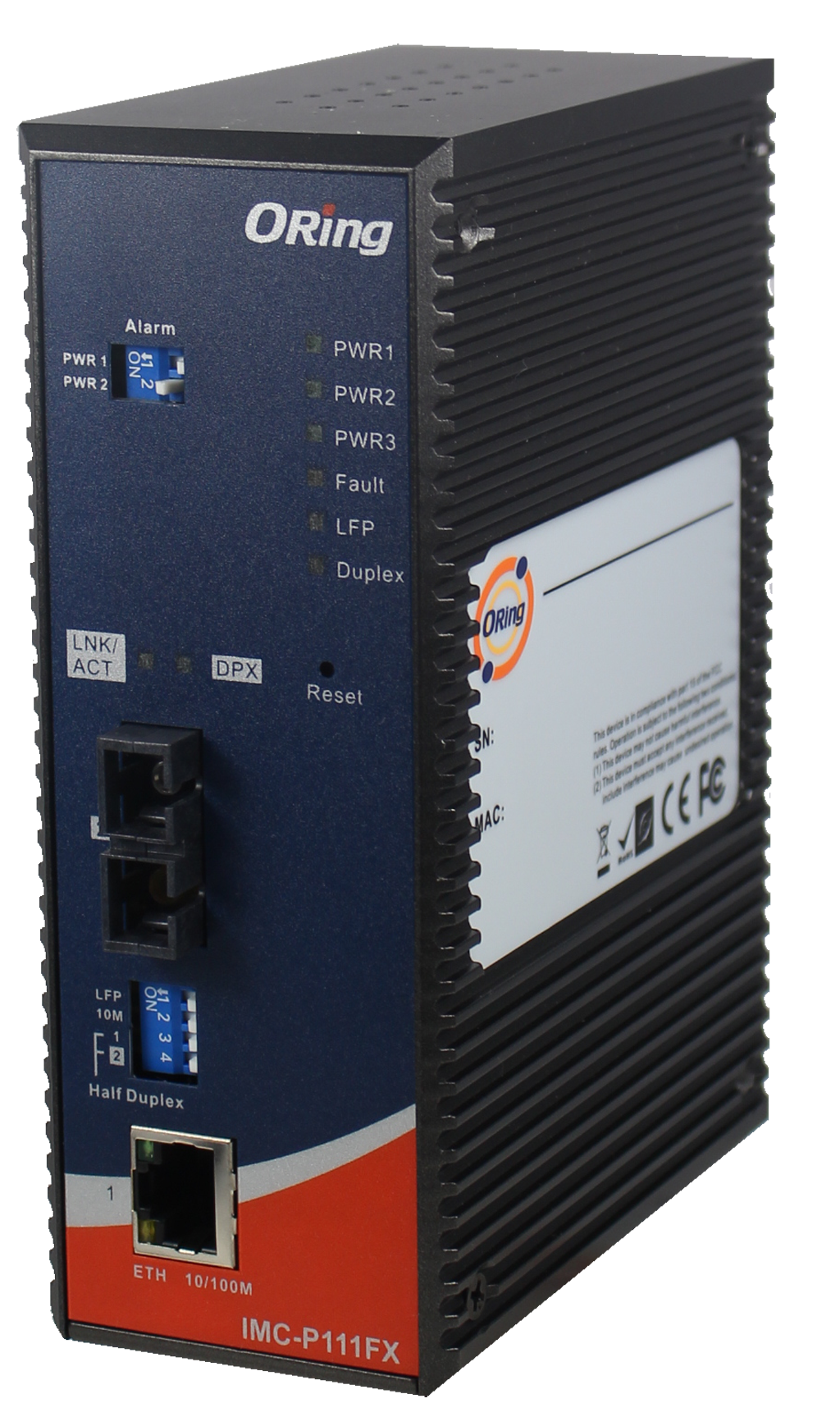
The IMC-P111FX-SS-SC-M12-HV is an industrial-grade Ethernet-to-fiber media converter designed for IEC 61850-3 and IEEE 1613 power substation and smart grid applications, as well as railway and rolling stock environments.
Product Name: IMC-P111FX-SS-SC-M12-HV
Article Number: IMC-P111FX-SS-SC-M12-HV
Series: IMC-P111FX / IMC-P111P M12 Series (part of the IMC-P111-M12 family)
Manufacturer: ORing Industrial Networking Corp.
Description: The model provides 1x 10/100Base-T(X) Ethernet port using an M12 D-coded connector and 1x 100Base-FX fiber port using SC single-mode optics. It is equipped with high-voltage AC power input (100–240VAC) and is engineered for harsh operating conditions with extreme temperatures, vibration, and shock.
--------------------------------------------------------------------
2. Key Features
• Fully compliant with IEC 61850-3 and IEEE 1613 standards for power substation and smart grid infrastructure
• EN50155-compliant for railway and rolling-stock applications
• Extends Ethernet communication via 100Base-FX single-mode fiber up to 30 km at 1310 nm
• Rugged M12 D-coded Ethernet connector ensures vibration- and shock-resistant connections
• Operating temperature range from -40 to 85 degrees Celsius
• High-voltage dual AC power input: 100–240VAC
• Supports auto-negotiation and auto-MDI/MDI-X on the LAN port
• Selectable DIP-switch configurations for LFP, speed, duplex modes, and power failure alarms
• LFP (Link Fault Pass-through) support for improved network diagnostic behavior
• Store-and-forward switching architecture
• IP-30 rated metal enclosure
• Relay output for power-failure alarm event notification
• Supports both DIN-rail and wall-mount installation
• LED indicators for power, link/activity, duplex, fiber status, LFP, and fault conditions
• Compatible with optional SFP modules (for P model), optional external power supplies, and various regional high-voltage versions
--------------------------------------------------------------------
3. Technical Specifications
Dimensions: 54.2 W x 106.1 D x 145.4 H mm (2.05 x 4.18 x 5.68 in)
Enclosure: IP-30 hardened metal housing
Weight: Approx. 833 g (HV model)
Operating Temperature: -40 to 85 degrees Celsius
Storage Temperature: -40 to 85 degrees Celsius
Operating Humidity: 5 to 95 percent non-condensing
Ethernet Interface:
• 1x 10/100Base-T(X) Ethernet port
• M12 D-coded connector
• Auto-MDI/MDI-X, auto-negotiation
• Full/half-duplex selectable via DIP-switch
Fiber Interface:
• 1x 100Base-FX single-mode SC port
• Fiber Diameter: 9/125 µm
• Wavelength: 1310 nm
• Typical Distance: 30 km
• Max Output Optical Power: -8 dBm
• Min Output Optical Power: -15 dBm
• Max Input Optical Power (saturation): 0 dBm
• Min Input Optical Power (sensitivity): -34 dBm
• Link Budget: 19 dB
Electrical:
• High-voltage (HV) input: Dual 100 to 240VAC on 8-pin terminal block
• Typical power consumption: 4.8 W at 100VAC, 5.8 W at 240VAC
• Overload protection: Present
• Reverse polarity protection: Present on terminal block
• Relay alarm output for power failure
Technology Standards:
• IEEE 802.3 for 10Base-T
• IEEE 802.3u for 100Base-T(X) and 100Base-FX
• IEEE 802.3x for flow control
LED Indicators:
• Power status (PWR1, PWR2)
• Link and Activity for Ethernet and fiber
• Duplex indicators
• LFP status
• Fault indicator
--------------------------------------------------------------------
4. Functionality
The IMC-P111FX-SS-SC-M12-HV converts electrical Ethernet signals to optical fiber using the 100Base-FX standard. This enables long-distance network extension (up to 30 km) in EMI-heavy or environmentally harsh locations.
The device uses robust M12 D-coded connectors suited for railway, vibration-prone machinery, or mobile industrial platforms.
LFP ensures that link failures on one side of the media converter propagate to the other side, enabling network control systems to detect communication loss quickly.
Use cases include:
• Power substations complying with IEC 61850-3
• Smart grid and utility automation
• Railway and rolling-stock communications (EN50155)
• Industrial plant networks, machine automation, and outdoor enclosures
• Long-distance Ethernet extension in electrically noisy sites
Compatibility:
• Ethernet devices using 10/100Base-T(X)
• Single-mode SC fiber networks
• AC power systems (100–240VAC)
• DIN-rail and wall-mounted industrial cabinets
--------------------------------------------------------------------
5. Components and Accessories
Included Components:
• IMC-P111-M12 unit (model dependent)
• DIN-rail mounting kit
• Wall-mounting kit
• Quick Installation Guide
Optional Accessories:
• SFP100 series (for P models): 100 Mbps SFP optical transceivers
• DR-45, DR-75, DR-120 series industrial power supplies
Connectors:
• M12 D-coded 4-pin Ethernet connector
• SC single-mode fiber port
• Terminal block connectors for AC power inputs, grounding, and relay output
--------------------------------------------------------------------
6. Installation and Setup
Mounting Options:
• DIN-rail: Attach DIN-rail kit to the rear of the converter and snap onto standard DIN-rail
• Wall-mount: Use provided wall plates and follow the marking and screw alignment procedure
Power Wiring (HV Model):
• Dual redundant AC inputs, 100–240VAC, connected via terminal block
• Secure connections using a flat-blade screwdriver
Grounding:
• Must connect grounding terminal to reduce EMI impact and ensure safe operation
Network Cabling:
• Ethernet: M12 D-coded connector, using Cat3/4/5 UTP for 10Base-T, Cat5 UTP for 100Base-TX; maximum 100 m length
• Fiber: Single-mode 9/125 µm SC connectors; ensure cross TX-to-RX wiring
DIP-Switch Configurable Options:
• DIP1 LFP enable/disable
• DIP2 Ethernet speed (10 Mbps or Auto 10/100)
• DIP3 Ethernet duplex mode
• DIP4 Fiber duplex mode
• Alarm DIP switches for PWR1 and PWR2 failure detection
--------------------------------------------------------------------
7. Performance and Capabilities
Speed:
• 10/100 Mbps Ethernet auto-negotiation
• 100 Mbps fiber transmission
Distance:
• 30 km typical range using single-mode fiber
Efficiency and Processing:
• Store-and-forward switching for error-free data transmission
• Full/half-duplex operation for both copper and fiber sides
Reliability:
• Redundant dual AC power inputs
• Relay failure alarms reduce downtime
• LFP ensures fast detection of link failures
Limitations:
• Single Ethernet port and single fiber port limit use to point-to-point or linear-chain topology
• No diagnostics via web interface (purely hardware-level configuration)
--------------------------------------------------------------------
8. Standards and Compliance
Industrial and Power Utility Standards:
• IEC 61850-3 for power automation
• IEEE 1613 for substation communications
Rail and Transportation:
• EN50155 (including EN50121-3-2 and EN50121-4)
• Meets rolling stock vibration and shock requirements
EMI/EMC:
• FCC Part 15 Class A
• CISPR/EN55022 Class A
• EN55011
EMS:
• EN61000-4-2 ESD
• EN61000-4-3 RS
• EN61000-4-4 EFT
• EN61000-4-5 Surge
• EN61000-4-6 CS
• EN61000-4-8
• EN61000-4-11
Environmental:
• Shock IEC60068-2-27
• Free Fall IEC60068-2-32
• Vibration IEC60068-2-6
Safety:
• EN60950-1
--------------------------------------------------------------------
9. Additional Information
Warranty:
• 5-year manufacturer warranty
Maintenance:
• Periodic inspection recommended for fiber connectors and M12 couplings
• Ensure proper grounding and environmental sealing when used outdoors
Support and Updates:
• Manufacturer: ORing Industrial Networking Corp.
• Website: www.oring-networking.com
• Technical Support Email: support@oring-networking.com
• Firmware is not applicable; device is hardware-configured
--------------------------------------------------------------------
This summary consolidates every technical detail provided for the IMC-P111FX-SS-SC-M12-HV, structured for engineering, procurement, and system-integration use.
--------------------------------------------------------------------
1. Product Overview
The IMC-P111FX-SS-SC-M12-HV is an industrial-grade Ethernet-to-fiber media converter designed for IEC 61850-3 and IEEE 1613 power substation and smart grid applications, as well as railway and rolling stock environments.
Product Name: IMC-P111FX-SS-SC-M12-HV
Article Number: IMC-P111FX-SS-SC-M12-HV
Series: IMC-P111FX / IMC-P111P M12 Series (part of the IMC-P111-M12 family)
Manufacturer: ORing Industrial Networking Corp.
Description: The model provides 1x 10/100Base-T(X) Ethernet port using an M12 D-coded connector and 1x 100Base-FX fiber port using SC single-mode optics. It is equipped with high-voltage AC power input (100–240VAC) and is engineered for harsh operating conditions with extreme temperatures, vibration, and shock.
--------------------------------------------------------------------
2. Key Features
• Fully compliant with IEC 61850-3 and IEEE 1613 standards for power substation and smart grid infrastructure
• EN50155-compliant for railway and rolling-stock applications
• Extends Ethernet communication via 100Base-FX single-mode fiber up to 30 km at 1310 nm
• Rugged M12 D-coded Ethernet connector ensures vibration- and shock-resistant connections
• Operating temperature range from -40 to 85 degrees Celsius
• High-voltage dual AC power input: 100–240VAC
• Supports auto-negotiation and auto-MDI/MDI-X on the LAN port
• Selectable DIP-switch configurations for LFP, speed, duplex modes, and power failure alarms
• LFP (Link Fault Pass-through) support for improved network diagnostic behavior
• Store-and-forward switching architecture
• IP-30 rated metal enclosure
• Relay output for power-failure alarm event notification
• Supports both DIN-rail and wall-mount installation
• LED indicators for power, link/activity, duplex, fiber status, LFP, and fault conditions
• Compatible with optional SFP modules (for P model), optional external power supplies, and various regional high-voltage versions
--------------------------------------------------------------------
3. Technical Specifications
Dimensions: 54.2 W x 106.1 D x 145.4 H mm (2.05 x 4.18 x 5.68 in)
Enclosure: IP-30 hardened metal housing
Weight: Approx. 833 g (HV model)
Operating Temperature: -40 to 85 degrees Celsius
Storage Temperature: -40 to 85 degrees Celsius
Operating Humidity: 5 to 95 percent non-condensing
Ethernet Interface:
• 1x 10/100Base-T(X) Ethernet port
• M12 D-coded connector
• Auto-MDI/MDI-X, auto-negotiation
• Full/half-duplex selectable via DIP-switch
Fiber Interface:
• 1x 100Base-FX single-mode SC port
• Fiber Diameter: 9/125 µm
• Wavelength: 1310 nm
• Typical Distance: 30 km
• Max Output Optical Power: -8 dBm
• Min Output Optical Power: -15 dBm
• Max Input Optical Power (saturation): 0 dBm
• Min Input Optical Power (sensitivity): -34 dBm
• Link Budget: 19 dB
Electrical:
• High-voltage (HV) input: Dual 100 to 240VAC on 8-pin terminal block
• Typical power consumption: 4.8 W at 100VAC, 5.8 W at 240VAC
• Overload protection: Present
• Reverse polarity protection: Present on terminal block
• Relay alarm output for power failure
Technology Standards:
• IEEE 802.3 for 10Base-T
• IEEE 802.3u for 100Base-T(X) and 100Base-FX
• IEEE 802.3x for flow control
LED Indicators:
• Power status (PWR1, PWR2)
• Link and Activity for Ethernet and fiber
• Duplex indicators
• LFP status
• Fault indicator
--------------------------------------------------------------------
4. Functionality
The IMC-P111FX-SS-SC-M12-HV converts electrical Ethernet signals to optical fiber using the 100Base-FX standard. This enables long-distance network extension (up to 30 km) in EMI-heavy or environmentally harsh locations.
The device uses robust M12 D-coded connectors suited for railway, vibration-prone machinery, or mobile industrial platforms.
LFP ensures that link failures on one side of the media converter propagate to the other side, enabling network control systems to detect communication loss quickly.
Use cases include:
• Power substations complying with IEC 61850-3
• Smart grid and utility automation
• Railway and rolling-stock communications (EN50155)
• Industrial plant networks, machine automation, and outdoor enclosures
• Long-distance Ethernet extension in electrically noisy sites
Compatibility:
• Ethernet devices using 10/100Base-T(X)
• Single-mode SC fiber networks
• AC power systems (100–240VAC)
• DIN-rail and wall-mounted industrial cabinets
--------------------------------------------------------------------
5. Components and Accessories
Included Components:
• IMC-P111-M12 unit (model dependent)
• DIN-rail mounting kit
• Wall-mounting kit
• Quick Installation Guide
Optional Accessories:
• SFP100 series (for P models): 100 Mbps SFP optical transceivers
• DR-45, DR-75, DR-120 series industrial power supplies
Connectors:
• M12 D-coded 4-pin Ethernet connector
• SC single-mode fiber port
• Terminal block connectors for AC power inputs, grounding, and relay output
--------------------------------------------------------------------
6. Installation and Setup
Mounting Options:
• DIN-rail: Attach DIN-rail kit to the rear of the converter and snap onto standard DIN-rail
• Wall-mount: Use provided wall plates and follow the marking and screw alignment procedure
Power Wiring (HV Model):
• Dual redundant AC inputs, 100–240VAC, connected via terminal block
• Secure connections using a flat-blade screwdriver
Grounding:
• Must connect grounding terminal to reduce EMI impact and ensure safe operation
Network Cabling:
• Ethernet: M12 D-coded connector, using Cat3/4/5 UTP for 10Base-T, Cat5 UTP for 100Base-TX; maximum 100 m length
• Fiber: Single-mode 9/125 µm SC connectors; ensure cross TX-to-RX wiring
DIP-Switch Configurable Options:
• DIP1 LFP enable/disable
• DIP2 Ethernet speed (10 Mbps or Auto 10/100)
• DIP3 Ethernet duplex mode
• DIP4 Fiber duplex mode
• Alarm DIP switches for PWR1 and PWR2 failure detection
--------------------------------------------------------------------
7. Performance and Capabilities
Speed:
• 10/100 Mbps Ethernet auto-negotiation
• 100 Mbps fiber transmission
Distance:
• 30 km typical range using single-mode fiber
Efficiency and Processing:
• Store-and-forward switching for error-free data transmission
• Full/half-duplex operation for both copper and fiber sides
Reliability:
• Redundant dual AC power inputs
• Relay failure alarms reduce downtime
• LFP ensures fast detection of link failures
Limitations:
• Single Ethernet port and single fiber port limit use to point-to-point or linear-chain topology
• No diagnostics via web interface (purely hardware-level configuration)
--------------------------------------------------------------------
8. Standards and Compliance
Industrial and Power Utility Standards:
• IEC 61850-3 for power automation
• IEEE 1613 for substation communications
Rail and Transportation:
• EN50155 (including EN50121-3-2 and EN50121-4)
• Meets rolling stock vibration and shock requirements
EMI/EMC:
• FCC Part 15 Class A
• CISPR/EN55022 Class A
• EN55011
EMS:
• EN61000-4-2 ESD
• EN61000-4-3 RS
• EN61000-4-4 EFT
• EN61000-4-5 Surge
• EN61000-4-6 CS
• EN61000-4-8
• EN61000-4-11
Environmental:
• Shock IEC60068-2-27
• Free Fall IEC60068-2-32
• Vibration IEC60068-2-6
Safety:
• EN60950-1
--------------------------------------------------------------------
9. Additional Information
Warranty:
• 5-year manufacturer warranty
Maintenance:
• Periodic inspection recommended for fiber connectors and M12 couplings
• Ensure proper grounding and environmental sealing when used outdoors
Support and Updates:
• Manufacturer: ORing Industrial Networking Corp.
• Website: www.oring-networking.com
• Technical Support Email: support@oring-networking.com
• Firmware is not applicable; device is hardware-configured
--------------------------------------------------------------------
This summary consolidates every technical detail provided for the IMC-P111FX-SS-SC-M12-HV, structured for engineering, procurement, and system-integration use.
-
 DataSheet_IMC-P111FX_IMC-P111P-M12_Series.pdf
PDF Catalog
DataSheet_IMC-P111FX_IMC-P111P-M12_Series.pdf
PDF Catalog
-
 QIG_IMC-P111-M12 Series.pdf
Manual
QIG_IMC-P111-M12 Series.pdf
Manual
Kein Zubehör vorhanden.