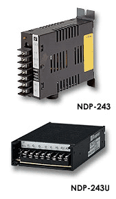
NDP-243
SUCHEN SIE DIE PASSENDE
INDUSTRIELLE LÖSUNG?
Entdecken Sie Embedded-, Kommunikations- und Automatisierungslösungen für Ihre Anwendung.
- Eight Analog Input Channels: Six differential and two single‑ended inputs for flexible signal connection.
- Wide Input Range: Programmable voltage ranges of ±10 V, ±5 V, ±1 V, ±500 mV, ±150 mV, and current measurement from 0 to 20 mA (via external 125 Ω resistor).
- High Resolution: 16‑bit A/D conversion ensures precise signal acquisition.
- Sampling Rate: 10 samples per second per channel, suitable for slow‑to‑medium dynamic signals.
- Electrical Isolation: 5000 Vrms isolation between analog input circuitry and communication/power sections for robust noise immunity and protection against ground loops.
- RS‑485 Communication Interface: Two‑wire, half‑duplex serial interface supporting baud rates from 1200 bps to 115.2 kbps.
- ADAM‑4017 Compatibility: Fully compatible with ADAM‑4017 command set and wiring, simplifying integration into existing systems.
- Programmable Host Watchdog Timer: Provides automatic fail‑safe output in case of host communication failure.
- Internal Watchdog: Monitors module operation and resets automatically upon internal fault detection.
- Compact Industrial Design: DIN‑rail or panel‑mountable ABS enclosure with screw‑terminal connectors for secure wiring.
- Software Configurable: All parameters—input range, baud rate, data format, and address—are programmable via ASCII commands.
- Ease of Integration: Operates as a slave device in a multi‑drop RS‑485 network of up to 256 modules.
- Wide Input Range: Programmable voltage ranges of ±10 V, ±5 V, ±1 V, ±500 mV, ±150 mV, and current measurement from 0 to 20 mA (via external 125 Ω resistor).
- High Resolution: 16‑bit A/D conversion ensures precise signal acquisition.
- Sampling Rate: 10 samples per second per channel, suitable for slow‑to‑medium dynamic signals.
- Electrical Isolation: 5000 Vrms isolation between analog input circuitry and communication/power sections for robust noise immunity and protection against ground loops.
- RS‑485 Communication Interface: Two‑wire, half‑duplex serial interface supporting baud rates from 1200 bps to 115.2 kbps.
- ADAM‑4017 Compatibility: Fully compatible with ADAM‑4017 command set and wiring, simplifying integration into existing systems.
- Programmable Host Watchdog Timer: Provides automatic fail‑safe output in case of host communication failure.
- Internal Watchdog: Monitors module operation and resets automatically upon internal fault detection.
- Compact Industrial Design: DIN‑rail or panel‑mountable ABS enclosure with screw‑terminal connectors for secure wiring.
- Software Configurable: All parameters—input range, baud rate, data format, and address—are programmable via ASCII commands.
- Ease of Integration: Operates as a slave device in a multi‑drop RS‑485 network of up to 256 modules.
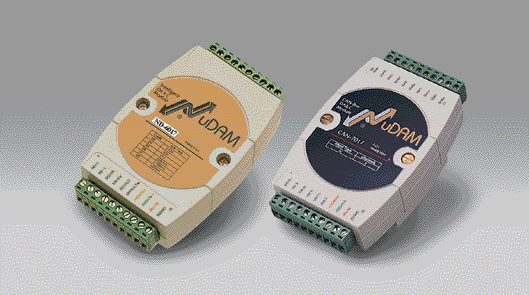
Comprehensive Product Summary – NuDAM ND‑6017 8‑Channel Analog Input Module
### 1. Product Overview
Product Name: NuDAM 8‑Channel Analog Input Module
Model: ND‑6017
Series: NuDAM‑6000 Series Data Acquisition Modules
Article Number: ND‑6017
Manufacturer: ADLINK Technology Inc.
The ND‑6017 is a high‑performance, isolated analog input module designed for distributed data acquisition and industrial process monitoring. It is part of ADLINK’s NuDAM‑6000 family, which provides modular, RS‑485‑based remote I/O solutions for analog and digital signal interfacing. The ND‑6017 offers eight analog input channels—six differential and two single‑ended—supporting voltage and current measurement with programmable ranges and high‑resolution A/D conversion.
### 2. Key Features
- Eight Analog Input Channels: Six differential and two single‑ended inputs for flexible signal connection.
- Wide Input Range: Programmable voltage ranges of ±10 V, ±5 V, ±1 V, ±500 mV, ±150 mV, and current measurement from 0 to 20 mA (via external 125 Ω resistor).
- High Resolution: 16‑bit A/D conversion ensures precise signal acquisition.
- Sampling Rate: 10 samples per second per channel, suitable for slow‑to‑medium dynamic signals.
- Electrical Isolation: 5000 Vrms isolation between analog input circuitry and communication/power sections for robust noise immunity and protection against ground loops.
- RS‑485 Communication Interface: Two‑wire, half‑duplex serial interface supporting baud rates from 1200 bps to 115.2 kbps.
- ADAM‑4017 Compatibility: Fully compatible with ADAM‑4017 command set and wiring, simplifying integration into existing systems.
- Programmable Host Watchdog Timer: Provides automatic fail‑safe output in case of host communication failure.
- Internal Watchdog: Monitors module operation and resets automatically upon internal fault detection.
- Compact Industrial Design: DIN‑rail or panel‑mountable ABS enclosure with screw‑terminal connectors for secure wiring.
- Software Configurable: All parameters—input range, baud rate, data format, and address—are programmable via ASCII commands.
- Ease of Integration: Operates as a slave device in a multi‑drop RS‑485 network of up to 256 modules.
### 3. Technical Specifications
Interface:
- Communication: RS‑485, 2‑wire, half‑duplex
- Baud Rate: 1200 / 2400 / 4800 / 9600 / 19.2 k / 38.4 k / 57.6 k / 115.2 k bps
- Protocol: ASCII command/response
Analog Input:
- Channels: 8 (6 differential + 2 single‑ended)
- Input Type: Voltage or current (with external resistor)
- Input Ranges: ±10 V, ±5 V, ±1 V, ±500 mV, ±150 mV
- Current Range: 0 – 20 mA (via external 125 Ω ± 1 % resistor)
- Resolution: 16 bits
- Accuracy: ±0.1 % of full‑scale range
- Sampling Rate: 10 samples/sec
- Input Impedance: > 100 kΩ (typical)
- Maximum Input Voltage: ±30 V DC relative to AGND (damage threshold)
- Isolation Voltage: 5000 Vrms between analog input and system
Power Requirements:
- Supply Voltage: +10 V DC to +30 V DC (unregulated)
- Power Consumption: 1.2 W typical
Environmental:
- Operating Temperature: –10 °C to +70 °C
- Storage Temperature: –25 °C to +80 °C
- Humidity: 5 % – 95 % RH, non‑condensing
- Case Material: ABS plastic with internal EMI shielding
- Isolation Protection: Optical and galvanic isolation
Mechanical:
- Mounting: DIN‑rail or panel mount
- Connectors: 20‑pin screw terminal block
- Dimensions (typical): approx. 72 mm (W) × 118 mm (D) × 25 mm (H)
- Weight: approx. 200 g
### 4. Functionality
The ND‑6017 converts analog voltage or current signals into digital data for transmission over an RS‑485 network. Each channel can be configured for differential or single‑ended measurement, allowing flexible connection to sensors, transducers, or process signals.
Operation Principle:
1. The analog input signal is multiplexed through an 8‑channel analog multiplexer.
2. The selected channel is digitized by a 16‑bit A/D converter.
3. The microprocessor processes the data, applies scaling and calibration, and transmits the result via RS‑485.
4. The host computer or PLC reads the data using ASCII commands.
Typical Applications:
- Industrial process monitoring (temperature, pressure, flow, voltage, current)
- Remote data acquisition systems
- Building automation and energy management
- Laboratory instrumentation
- SCADA and distributed control systems
Compatibility:
- Fully compatible with ADLINK NuDAM‑6000 series modules and ADAM‑4017 command set.
- Communicates with any RS‑485 master (PC, PLC, or embedded controller).
- Supported by ADLINK’s NuDAM Administration Utility for configuration and calibration.
### 5. Components & Accessories
Included Components:
- ND‑6017 module
- Detachable screw‑terminal block for signal and power wiring
- Quick‑start and safety documentation
Optional Accessories:
- RS‑232 to RS‑485 converter (ND‑6520)
- USB to RS‑485 converter (ND‑6530)
- RS‑485 repeater (ND‑6510)
- 125 Ω precision resistors for current measurement
- DIN‑rail mounting kit
- Shielded twisted‑pair communication cable (recommended 22–26 AWG)
Connectors (Pin Assignment):
1 – Vin5+ Differential + input CH5
2 – Vin5– Differential – input CH5
3 – Vin6+ Single‑ended input CH6
4 – AGND Analog ground (CH6 & CH7)
5 – Vin7+ Single‑ended input CH7
6 – DEFAULT* Initialization pin (short to GND for default mode)
7 – (Y) DATA+ RS‑485 data line (+)
8 – (G) DATA– RS‑485 data line (–)
9 – (R) +Vs Power input (+10 V to +30 V DC)
10 – (B) GND Power ground
11–20 – Vin0± to Vin4± Differential inputs CH0–CH4
### 6. Installation & Setup
Requirements:
- DC power supply +10 V to +30 V (typical 24 V DC)
- RS‑485 network connection (twisted‑pair cable, 120 Ω termination at both ends)
- Host computer or controller with RS‑232/RS‑485 interface
Mounting Options:
- DIN‑rail mounting (standard)
- Panel or wall mounting
Configuration Procedure:
1. Connect the ND‑6017 to the RS‑485 bus (DATA+ and DATA–).
2. Connect power supply to +Vs and GND.
3. For first‑time setup, short the DEFAULT* pin to GND and power ON to enter default mode (Address 00, 9600 bps, no checksum).
4. Use the NuDAM Administration Utility or ASCII commands to assign a unique address, baud rate, and input range.
5. Remove the DEFAULT* short and power cycle the module.
6. Verify communication using the “Read Configuration” command ($ Addr 2 <CR>).
Wiring Guidelines:
- Use shielded twisted‑pair cable for RS‑485 lines.
- Maintain consistent polarity (DATA+ to DATA+, DATA– to DATA–).
- Terminate both ends of the bus with 120 Ω resistors.
- Connect shields to protective earth at one or multiple points to reduce EMI.
### 7. Performance & Capabilities
Measurement Performance:
- Resolution: 16 bits (1 part in 65,536)
- Accuracy: ±0.1 % of FSR
- Conversion Rate: 10 samples/sec
- Bandwidth: 14 Hz (typical)
- Input Impedance: > 100 kΩ
- Common‑Mode Rejection: > 100 dB (typical)
- Isolation: 5000 Vrms channel/system
Electrical Protection:
- Over‑voltage protection up to ±30 V DC
- Optical isolation between field and logic circuits
- Watchdog reset on communication or internal fault
Limitations:
- Not suitable for high‑frequency or transient signal capture (> 14 Hz bandwidth).
- Requires external resistor for current measurement.
- Single‑ended channels share common ground (AGND).
Reliability Features:
- Hardware watchdog resets module on fault.
- Host watchdog ensures safe output state if communication is lost.
- EEPROM retains configuration and calibration data.
### 8. Standards & Compliance
- Communication Standard: EIA RS‑485 (two‑wire, half‑duplex)
- Isolation: 5000 Vrms galvanic isolation between I/O and logic
- EMI/RFI Protection: Internal shielding and surface coating for noise immunity
- Environmental Protection: Conformal coating for humidity and chemical resistance
- CE Compliance: Class A industrial emission standard
- Safety: Designed for industrial low‑voltage DC systems (10–30 V DC)
- Compatibility: ADAM‑4017 protocol compatible; interoperable with NuDAM network modules (ND‑6520, ND‑6530, ND‑6510).
### 9. Additional Information
Calibration:
- Factory‑calibrated for all input ranges.
- Field calibration supported via ASCII commands:
- Offset Calibration ($ Addr 1 <CR>)
- Span Calibration ($ Addr 0 <CR>)
- Recommended calibration interval: 12 months.
Maintenance:
- Periodically verify wiring integrity and terminal tightness.
- Keep module away from strong magnetic fields and high‑voltage sources.
- Clean enclosure with dry, non‑conductive cloth only.
Firmware & Software Support:
- Firmware upgradable via RS‑485.
- Supported by NuDAM Administration Utility (Windows 95 – Windows 10).
- ASCII command set documented in NuDAM‑6000 User’s Guide.
Warranty:
- One‑year limited warranty against defects in materials and workmanship from date of purchase.
- Warranty void if module is modified, misused, or operated beyond specifications.
Technical Support:
- ADLINK Technology Inc. provides online resources, manuals, and firmware updates.
- Contact regional ADLINK service centers for calibration or repair.
### Summary
The ADLINK ND‑6017 is a robust, high‑accuracy, 8‑channel analog input module engineered for distributed industrial data acquisition. With its 16‑bit resolution, programmable input ranges, and 5000 Vrms isolation, it ensures reliable measurement of voltage and current signals in harsh environments. The RS‑485 interface allows long‑distance, multi‑drop networking of up to 256 modules, making it ideal for scalable SCADA and process control systems. Its compatibility with ADAM‑4017 command sets, watchdog protection, and easy configuration via ASCII commands or NuDAM Administration Utility make it a versatile and dependable component for industrial automation, laboratory instrumentation, and remote monitoring applications.

### 1. Product Overview
Product Name: NuDAM 8‑Channel Analog Input Module
Model: ND‑6017
Series: NuDAM‑6000 Series Data Acquisition Modules
Article Number: ND‑6017
Manufacturer: ADLINK Technology Inc.
The ND‑6017 is a high‑performance, isolated analog input module designed for distributed data acquisition and industrial process monitoring. It is part of ADLINK’s NuDAM‑6000 family, which provides modular, RS‑485‑based remote I/O solutions for analog and digital signal interfacing. The ND‑6017 offers eight analog input channels—six differential and two single‑ended—supporting voltage and current measurement with programmable ranges and high‑resolution A/D conversion.
### 2. Key Features
- Eight Analog Input Channels: Six differential and two single‑ended inputs for flexible signal connection.
- Wide Input Range: Programmable voltage ranges of ±10 V, ±5 V, ±1 V, ±500 mV, ±150 mV, and current measurement from 0 to 20 mA (via external 125 Ω resistor).
- High Resolution: 16‑bit A/D conversion ensures precise signal acquisition.
- Sampling Rate: 10 samples per second per channel, suitable for slow‑to‑medium dynamic signals.
- Electrical Isolation: 5000 Vrms isolation between analog input circuitry and communication/power sections for robust noise immunity and protection against ground loops.
- RS‑485 Communication Interface: Two‑wire, half‑duplex serial interface supporting baud rates from 1200 bps to 115.2 kbps.
- ADAM‑4017 Compatibility: Fully compatible with ADAM‑4017 command set and wiring, simplifying integration into existing systems.
- Programmable Host Watchdog Timer: Provides automatic fail‑safe output in case of host communication failure.
- Internal Watchdog: Monitors module operation and resets automatically upon internal fault detection.
- Compact Industrial Design: DIN‑rail or panel‑mountable ABS enclosure with screw‑terminal connectors for secure wiring.
- Software Configurable: All parameters—input range, baud rate, data format, and address—are programmable via ASCII commands.
- Ease of Integration: Operates as a slave device in a multi‑drop RS‑485 network of up to 256 modules.
### 3. Technical Specifications
Interface:
- Communication: RS‑485, 2‑wire, half‑duplex
- Baud Rate: 1200 / 2400 / 4800 / 9600 / 19.2 k / 38.4 k / 57.6 k / 115.2 k bps
- Protocol: ASCII command/response
Analog Input:
- Channels: 8 (6 differential + 2 single‑ended)
- Input Type: Voltage or current (with external resistor)
- Input Ranges: ±10 V, ±5 V, ±1 V, ±500 mV, ±150 mV
- Current Range: 0 – 20 mA (via external 125 Ω ± 1 % resistor)
- Resolution: 16 bits
- Accuracy: ±0.1 % of full‑scale range
- Sampling Rate: 10 samples/sec
- Input Impedance: > 100 kΩ (typical)
- Maximum Input Voltage: ±30 V DC relative to AGND (damage threshold)
- Isolation Voltage: 5000 Vrms between analog input and system
Power Requirements:
- Supply Voltage: +10 V DC to +30 V DC (unregulated)
- Power Consumption: 1.2 W typical
Environmental:
- Operating Temperature: –10 °C to +70 °C
- Storage Temperature: –25 °C to +80 °C
- Humidity: 5 % – 95 % RH, non‑condensing
- Case Material: ABS plastic with internal EMI shielding
- Isolation Protection: Optical and galvanic isolation
Mechanical:
- Mounting: DIN‑rail or panel mount
- Connectors: 20‑pin screw terminal block
- Dimensions (typical): approx. 72 mm (W) × 118 mm (D) × 25 mm (H)
- Weight: approx. 200 g
### 4. Functionality
The ND‑6017 converts analog voltage or current signals into digital data for transmission over an RS‑485 network. Each channel can be configured for differential or single‑ended measurement, allowing flexible connection to sensors, transducers, or process signals.
Operation Principle:
1. The analog input signal is multiplexed through an 8‑channel analog multiplexer.
2. The selected channel is digitized by a 16‑bit A/D converter.
3. The microprocessor processes the data, applies scaling and calibration, and transmits the result via RS‑485.
4. The host computer or PLC reads the data using ASCII commands.
Typical Applications:
- Industrial process monitoring (temperature, pressure, flow, voltage, current)
- Remote data acquisition systems
- Building automation and energy management
- Laboratory instrumentation
- SCADA and distributed control systems
Compatibility:
- Fully compatible with ADLINK NuDAM‑6000 series modules and ADAM‑4017 command set.
- Communicates with any RS‑485 master (PC, PLC, or embedded controller).
- Supported by ADLINK’s NuDAM Administration Utility for configuration and calibration.
### 5. Components & Accessories
Included Components:
- ND‑6017 module
- Detachable screw‑terminal block for signal and power wiring
- Quick‑start and safety documentation
Optional Accessories:
- RS‑232 to RS‑485 converter (ND‑6520)
- USB to RS‑485 converter (ND‑6530)
- RS‑485 repeater (ND‑6510)
- 125 Ω precision resistors for current measurement
- DIN‑rail mounting kit
- Shielded twisted‑pair communication cable (recommended 22–26 AWG)
Connectors (Pin Assignment):
1 – Vin5+ Differential + input CH5
2 – Vin5– Differential – input CH5
3 – Vin6+ Single‑ended input CH6
4 – AGND Analog ground (CH6 & CH7)
5 – Vin7+ Single‑ended input CH7
6 – DEFAULT* Initialization pin (short to GND for default mode)
7 – (Y) DATA+ RS‑485 data line (+)
8 – (G) DATA– RS‑485 data line (–)
9 – (R) +Vs Power input (+10 V to +30 V DC)
10 – (B) GND Power ground
11–20 – Vin0± to Vin4± Differential inputs CH0–CH4
### 6. Installation & Setup
Requirements:
- DC power supply +10 V to +30 V (typical 24 V DC)
- RS‑485 network connection (twisted‑pair cable, 120 Ω termination at both ends)
- Host computer or controller with RS‑232/RS‑485 interface
Mounting Options:
- DIN‑rail mounting (standard)
- Panel or wall mounting
Configuration Procedure:
1. Connect the ND‑6017 to the RS‑485 bus (DATA+ and DATA–).
2. Connect power supply to +Vs and GND.
3. For first‑time setup, short the DEFAULT* pin to GND and power ON to enter default mode (Address 00, 9600 bps, no checksum).
4. Use the NuDAM Administration Utility or ASCII commands to assign a unique address, baud rate, and input range.
5. Remove the DEFAULT* short and power cycle the module.
6. Verify communication using the “Read Configuration” command ($ Addr 2 <CR>).
Wiring Guidelines:
- Use shielded twisted‑pair cable for RS‑485 lines.
- Maintain consistent polarity (DATA+ to DATA+, DATA– to DATA–).
- Terminate both ends of the bus with 120 Ω resistors.
- Connect shields to protective earth at one or multiple points to reduce EMI.
### 7. Performance & Capabilities
Measurement Performance:
- Resolution: 16 bits (1 part in 65,536)
- Accuracy: ±0.1 % of FSR
- Conversion Rate: 10 samples/sec
- Bandwidth: 14 Hz (typical)
- Input Impedance: > 100 kΩ
- Common‑Mode Rejection: > 100 dB (typical)
- Isolation: 5000 Vrms channel/system
Electrical Protection:
- Over‑voltage protection up to ±30 V DC
- Optical isolation between field and logic circuits
- Watchdog reset on communication or internal fault
Limitations:
- Not suitable for high‑frequency or transient signal capture (> 14 Hz bandwidth).
- Requires external resistor for current measurement.
- Single‑ended channels share common ground (AGND).
Reliability Features:
- Hardware watchdog resets module on fault.
- Host watchdog ensures safe output state if communication is lost.
- EEPROM retains configuration and calibration data.
### 8. Standards & Compliance
- Communication Standard: EIA RS‑485 (two‑wire, half‑duplex)
- Isolation: 5000 Vrms galvanic isolation between I/O and logic
- EMI/RFI Protection: Internal shielding and surface coating for noise immunity
- Environmental Protection: Conformal coating for humidity and chemical resistance
- CE Compliance: Class A industrial emission standard
- Safety: Designed for industrial low‑voltage DC systems (10–30 V DC)
- Compatibility: ADAM‑4017 protocol compatible; interoperable with NuDAM network modules (ND‑6520, ND‑6530, ND‑6510).
### 9. Additional Information
Calibration:
- Factory‑calibrated for all input ranges.
- Field calibration supported via ASCII commands:
- Offset Calibration ($ Addr 1 <CR>)
- Span Calibration ($ Addr 0 <CR>)
- Recommended calibration interval: 12 months.
Maintenance:
- Periodically verify wiring integrity and terminal tightness.
- Keep module away from strong magnetic fields and high‑voltage sources.
- Clean enclosure with dry, non‑conductive cloth only.
Firmware & Software Support:
- Firmware upgradable via RS‑485.
- Supported by NuDAM Administration Utility (Windows 95 – Windows 10).
- ASCII command set documented in NuDAM‑6000 User’s Guide.
Warranty:
- One‑year limited warranty against defects in materials and workmanship from date of purchase.
- Warranty void if module is modified, misused, or operated beyond specifications.
Technical Support:
- ADLINK Technology Inc. provides online resources, manuals, and firmware updates.
- Contact regional ADLINK service centers for calibration or repair.
### Summary
The ADLINK ND‑6017 is a robust, high‑accuracy, 8‑channel analog input module engineered for distributed industrial data acquisition. With its 16‑bit resolution, programmable input ranges, and 5000 Vrms isolation, it ensures reliable measurement of voltage and current signals in harsh environments. The RS‑485 interface allows long‑distance, multi‑drop networking of up to 256 modules, making it ideal for scalable SCADA and process control systems. Its compatibility with ADAM‑4017 command sets, watchdog protection, and easy configuration via ASCII commands or NuDAM Administration Utility make it a versatile and dependable component for industrial automation, laboratory instrumentation, and remote monitoring applications.
-
ND-6024_Datasheet_9.pdf
PDF Catalog