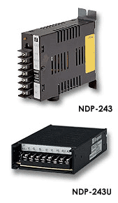
NDP-243
SUCHEN SIE DIE PASSENDE
INDUSTRIELLE LÖSUNG?
Entdecken Sie Embedded-, Kommunikations- und Automatisierungslösungen für Ihre Anwendung.
- Four Bipolar Analog Output Channels: Each channel provides a programmable ±10 V output range with 12‑bit resolution.
- Integrated Digital Inputs: Seven TTL‑level digital input channels for monitoring or triggering external events.
- High Isolation: 5000 Vrms optical isolation between communication, power, and I/O circuitry ensures electrical safety and noise immunity.
- RS‑485 Communication Interface: Two‑wire, half‑duplex serial interface supporting up to 115.2 kbps for multi‑drop networking of up to 256 modules.
- Programmable Watchdog Timers:
- Host Watchdog: Detects host communication failure and forces outputs to a predefined safe state.
- Internal Watchdog: Monitors internal microprocessor operation and resets the module in case of malfunction.
- High Accuracy and Stability: ±0.02 % of full‑scale range (FSR) accuracy with low gain drift (10 ppm FSR/°C).
- Compact Industrial Design: DIN‑rail or panel‑mountable ABS enclosure with screw‑terminal connectors for secure wiring.
- Software Configurable: All parameters (output range, baud rate, watchdog, safe values) are programmable via ASCII command set.
- Safety and Reliability: Power‑on safe values, watchdog reset, and galvanic isolation protect both the module and connected equipment.
- Integrated Digital Inputs: Seven TTL‑level digital input channels for monitoring or triggering external events.
- High Isolation: 5000 Vrms optical isolation between communication, power, and I/O circuitry ensures electrical safety and noise immunity.
- RS‑485 Communication Interface: Two‑wire, half‑duplex serial interface supporting up to 115.2 kbps for multi‑drop networking of up to 256 modules.
- Programmable Watchdog Timers:
- Host Watchdog: Detects host communication failure and forces outputs to a predefined safe state.
- Internal Watchdog: Monitors internal microprocessor operation and resets the module in case of malfunction.
- High Accuracy and Stability: ±0.02 % of full‑scale range (FSR) accuracy with low gain drift (10 ppm FSR/°C).
- Compact Industrial Design: DIN‑rail or panel‑mountable ABS enclosure with screw‑terminal connectors for secure wiring.
- Software Configurable: All parameters (output range, baud rate, watchdog, safe values) are programmable via ASCII command set.
- Safety and Reliability: Power‑on safe values, watchdog reset, and galvanic isolation protect both the module and connected equipment.
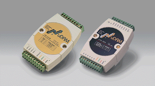
Comprehensive Product Summary – NuDAM ND‑6024 Analog Output Module
### 1. Product Overview
Product Name: NuDAM Analog Output Module
Model: ND‑6024
Series: NuDAM‑6000 Series
Article Number: ND‑6024
Manufacturer: ADLINK Technology Inc. (Taiwan)
The ND‑6024 is a four‑channel bipolar analog output module designed for industrial data acquisition and control applications. It is part of ADLINK’s NuDAM‑6000 distributed I/O system, which communicates via the RS‑485 standard. The module provides high‑precision analog voltage outputs with integrated digital input channels, galvanic isolation, and watchdog protection for reliable operation in harsh industrial environments.
### 2. Key Features
- Four Bipolar Analog Output Channels: Each channel provides a programmable ±10 V output range with 12‑bit resolution.
- Integrated Digital Inputs: Seven TTL‑level digital input channels for monitoring or triggering external events.
- High Isolation: 5000 Vrms optical isolation between communication, power, and I/O circuitry ensures electrical safety and noise immunity.
- RS‑485 Communication Interface: Two‑wire, half‑duplex serial interface supporting up to 115.2 kbps for multi‑drop networking of up to 256 modules.
- Programmable Watchdog Timers:
- Host Watchdog: Detects host communication failure and forces outputs to a predefined safe state.
- Internal Watchdog: Monitors internal microprocessor operation and resets the module in case of malfunction.
- High Accuracy and Stability: ±0.02 % of full‑scale range (FSR) accuracy with low gain drift (10 ppm FSR/°C).
- Compact Industrial Design: DIN‑rail or panel‑mountable ABS enclosure with screw‑terminal connectors for secure wiring.
- Software Configurable: All parameters (output range, baud rate, watchdog, safe values) are programmable via ASCII command set.
- Safety and Reliability: Power‑on safe values, watchdog reset, and galvanic isolation protect both the module and connected equipment.
### 3. Technical Specifications
Interface:
- Communication: RS‑485, 2‑wire, half‑duplex
- Baud Rate: 1200 – 115,200 bps (default = 9600 bps)
- Protocol: ASCII command/response
Analog Output:
- Channels: 4 differential voltage outputs
- Output Range: ±10 V
- Resolution: 12 bits (1 LSB ≈ 4.88 mV)
- Accuracy: ±0.02 % FSR (maximum)
- Output Type: Differential, bipolar
- Output Current Capability: ±10 µA (typical)
- Sampling Rate: 100 samples/s (aggregate)
- Gain Drift: 10 ppm FSR/°C
- Output Impedance: < 0.1 Ω
- Load Resistance: ≥ 2 kΩ recommended
Digital Input:
- Channels: 7 TTL‑compatible inputs
- Logic 0: 0 – 0.8 V
- Logic 1: 2.0 – 5.0 V
- Internal Pull‑up Resistor: 10 kΩ to +5 V
Isolation:
- Channel‑to‑System Isolation: 5000 Vrms (optical)
Power Requirements:
- Supply Voltage: +10 V DC to +30 V DC (unregulated)
- Power Consumption: 1.848 W typical
Environmental:
- Operating Temperature: –10 °C to +70 °C
- Storage Temperature: –25 °C to +80 °C
- Humidity: 5 % – 95 % RH, non‑condensing
Mechanical:
- Enclosure: ABS plastic with internal EMI shielding
- Mounting: DIN‑rail or panel mount
- Connectors: 20‑pin screw terminal block
- Isolation Barrier: Optical and DC‑DC converter isolation
### 4. Functionality
The ND‑6024 converts digital commands received via the RS‑485 network into precise analog voltage outputs. Each channel’s output is generated by a 12‑bit DAC controlled by an onboard microprocessor. The module supports bipolar ±10 V output for driving actuators, transducers, or control loops.
Operation Principle:
1. The host computer sends ASCII‑encoded commands through the RS‑485 bus.
2. The ND‑6024’s microcontroller interprets the command, updates the DAC registers, and outputs the corresponding analog voltage.
3. The module can store power‑on default values and safe values to ensure predictable behavior after resets or communication loss.
4. Digital inputs can be read synchronously or asynchronously for event monitoring or interlocking logic.
Typical Applications:
- Process control and automation systems
- Analog signal generation for test benches
- Industrial equipment actuation (valves, drives, proportional controls)
- SCADA and distributed control networks
- Laboratory instrumentation and data acquisition systems
Compatibility:
- Fully compatible with other NuDAM‑6000 modules (ND‑601x, ND‑605x, ND‑606x, ND‑6080).
- Communicates with ADLINK ND‑6520/6530/6531 converters for RS‑232/USB/RS‑485 integration.
- Supported by ADLINK NuDAM Administration Utility and standard serial communication software.
### 5. Components & Accessories
Included Components:
- ND‑6024 module (main unit)
- 20‑pin removable screw terminal block
- User manual and configuration guide (digital)
Optional Accessories:
- ND‑6520 RS‑232 ↔ RS‑485 converter
- ND‑6530 USB ↔ RS‑485 converter
- ND‑6510 RS‑485 repeater (for extended networks)
- DIN‑rail mounting kit
- Shielded twisted‑pair communication cables (120 Ω characteristic impedance)
- 120 Ω termination resistors for bus ends
Connectors and Pin Assignments:
1 – 5: Digital Inputs 0–4
6: Default* (initialization pin)
7: RS‑485 Data +
8: RS‑485 Data –
9: +Vs (10–30 V DC)
10: GND
11–18: Analog Output A–D (positive/negative pairs)
19–20: Digital Inputs 5–6
### 6. Installation & Setup
Requirements:
- DC power supply +10 V to +30 V DC
- RS‑485 network connection (twisted‑pair cable, 120 Ω termination)
- Host computer with RS‑232 or USB port and appropriate converter (ND‑6520/6530)
Mounting Options:
- DIN‑rail mounting (standard 35 mm rail)
- Panel or wall mounting via captive hardware
Configuration Procedure:
1. Initialization:
- Connect the *DEFAULT* pin to GND and power on to enter default mode.
- Default settings: Address = 01h, Baud = 9600 bps, Checksum = Disabled.
2. Address & Baud Setup:
- Use the NuDAM Administration Utility or ASCII command `%` to assign a unique address (00–FF hex) and desired baud rate.
3. Network Wiring:
- Connect RS‑485 Data + and Data – lines in daisy‑chain topology.
- Install 120 Ω termination resistors at both ends of the bus.
- Use shielded twisted‑pair cable; connect shield to protective earth.
4. Power Connection:
- Connect +Vs (10–30 V DC) and GND to a regulated supply.
5. Verification:
- Use the Administration Utility to detect the module and verify communication.
6. Output Calibration (if required):
- Perform trim calibration using a precision voltmeter and the “Trim Calibration” command.
### 7. Performance & Capabilities
Analog Output Performance:
- Output Range: ±10 V
- Resolution: 12 bits (4096 steps)
- Step Size: ≈ 4.88 mV per LSB
- Accuracy: ±0.02 % FSR
- Linearity: ±1 LSB typical
- Output Update Rate: 100 samples/s
- Temperature Drift: 10 ppm FSR/°C
- Output Stability: < 0.01 % FSR/hour
Digital Input Performance:
- Input Type: TTL logic
- Input Delay: < 1 ms typical
- Isolation: 5000 Vrms
System Capabilities:
- Up to 256 modules per RS‑485 network
- Maximum cable length: 1200 m (4000 ft)
- Multi‑drop topology supported (simple, branch, or free topology)
- Automatic recovery via watchdog reset
Limitations:
- Analog output limited to ±10 V (no current output mode)
- Digital inputs are TTL‑level only (no isolation)
- Requires external termination for long bus segments
### 8. Standards & Compliance
- Communication Standard: EIA RS‑485 (2‑wire, half‑duplex)
- Isolation Voltage: 5000 Vrms (I/O ↔ Logic ↔ Communication)
- Safety & EMC: Designed for industrial environments with EMI shielding and surge protection
- CE Compliance: Class A industrial device
- Environmental Protection: Conformal coating on PCB for humidity and chemical resistance
- RoHS: Compliant with lead‑free manufacturing standards
### 9. Additional Information
Warranty:
- One‑year limited warranty from date of purchase covering defects in materials and workmanship.
- Excludes damage due to misuse, modification, or operation beyond specifications.
Support & Maintenance:
- ADLINK provides technical documentation, firmware updates, and configuration utilities.
- Modules can be recalibrated using the NuDAM Administration Utility and precision instruments.
- Recommended periodic verification of output accuracy every 12 months.
Software & Utilities:
- NuDAM Administration Utility: Windows‑based configuration and monitoring tool.
- Command Set: ASCII‑based protocol supporting configuration, readback, calibration, and watchdog control.
- Integration: Compatible with SCADA, LabVIEW, MATLAB, and custom serial applications.
Calibration & Adjustment:
- Factory calibrated for ±10 V output range.
- Field calibration supported via “Trim Calibration” and “Save Power‑On Value” commands.
- Calibration accuracy verified using a 5½‑digit multimeter.
Maintenance Recommendations:
- Use shielded cables and proper grounding to minimize noise.
- Avoid installation near high‑power electrical equipment.
- Ensure stable DC supply (ripple < 50 mV).
- Inspect terminal connections periodically for corrosion or looseness.
Firmware & Updates:
- Firmware revision displayed via command `$F`.
- Updates available through ADLINK support for enhanced functionality or bug fixes.
Safety Notes:
- Do not connect or disconnect wiring while powered.
- Ensure the *DEFAULT* pin is only grounded during configuration.
- Observe polarity when wiring power and RS‑485 lines.
### Summary
The ADLINK NuDAM ND‑6024 is a robust, high‑precision, four‑channel analog output module with integrated digital inputs, designed for distributed industrial control systems. Its 12‑bit bipolar ±10 V outputs, 5000 V isolation, and RS‑485 communication make it ideal for remote analog signal generation and process control. With programmable watchdogs, safe‑state outputs, and comprehensive software configurability, the ND‑6024 ensures reliable, deterministic operation in demanding automation environments.
This module exemplifies ADLINK’s modular approach to distributed I/O—scalable, networkable, and engineered for long‑term stability and industrial resilience.

### 1. Product Overview
Product Name: NuDAM Analog Output Module
Model: ND‑6024
Series: NuDAM‑6000 Series
Article Number: ND‑6024
Manufacturer: ADLINK Technology Inc. (Taiwan)
The ND‑6024 is a four‑channel bipolar analog output module designed for industrial data acquisition and control applications. It is part of ADLINK’s NuDAM‑6000 distributed I/O system, which communicates via the RS‑485 standard. The module provides high‑precision analog voltage outputs with integrated digital input channels, galvanic isolation, and watchdog protection for reliable operation in harsh industrial environments.
### 2. Key Features
- Four Bipolar Analog Output Channels: Each channel provides a programmable ±10 V output range with 12‑bit resolution.
- Integrated Digital Inputs: Seven TTL‑level digital input channels for monitoring or triggering external events.
- High Isolation: 5000 Vrms optical isolation between communication, power, and I/O circuitry ensures electrical safety and noise immunity.
- RS‑485 Communication Interface: Two‑wire, half‑duplex serial interface supporting up to 115.2 kbps for multi‑drop networking of up to 256 modules.
- Programmable Watchdog Timers:
- Host Watchdog: Detects host communication failure and forces outputs to a predefined safe state.
- Internal Watchdog: Monitors internal microprocessor operation and resets the module in case of malfunction.
- High Accuracy and Stability: ±0.02 % of full‑scale range (FSR) accuracy with low gain drift (10 ppm FSR/°C).
- Compact Industrial Design: DIN‑rail or panel‑mountable ABS enclosure with screw‑terminal connectors for secure wiring.
- Software Configurable: All parameters (output range, baud rate, watchdog, safe values) are programmable via ASCII command set.
- Safety and Reliability: Power‑on safe values, watchdog reset, and galvanic isolation protect both the module and connected equipment.
### 3. Technical Specifications
Interface:
- Communication: RS‑485, 2‑wire, half‑duplex
- Baud Rate: 1200 – 115,200 bps (default = 9600 bps)
- Protocol: ASCII command/response
Analog Output:
- Channels: 4 differential voltage outputs
- Output Range: ±10 V
- Resolution: 12 bits (1 LSB ≈ 4.88 mV)
- Accuracy: ±0.02 % FSR (maximum)
- Output Type: Differential, bipolar
- Output Current Capability: ±10 µA (typical)
- Sampling Rate: 100 samples/s (aggregate)
- Gain Drift: 10 ppm FSR/°C
- Output Impedance: < 0.1 Ω
- Load Resistance: ≥ 2 kΩ recommended
Digital Input:
- Channels: 7 TTL‑compatible inputs
- Logic 0: 0 – 0.8 V
- Logic 1: 2.0 – 5.0 V
- Internal Pull‑up Resistor: 10 kΩ to +5 V
Isolation:
- Channel‑to‑System Isolation: 5000 Vrms (optical)
Power Requirements:
- Supply Voltage: +10 V DC to +30 V DC (unregulated)
- Power Consumption: 1.848 W typical
Environmental:
- Operating Temperature: –10 °C to +70 °C
- Storage Temperature: –25 °C to +80 °C
- Humidity: 5 % – 95 % RH, non‑condensing
Mechanical:
- Enclosure: ABS plastic with internal EMI shielding
- Mounting: DIN‑rail or panel mount
- Connectors: 20‑pin screw terminal block
- Isolation Barrier: Optical and DC‑DC converter isolation
### 4. Functionality
The ND‑6024 converts digital commands received via the RS‑485 network into precise analog voltage outputs. Each channel’s output is generated by a 12‑bit DAC controlled by an onboard microprocessor. The module supports bipolar ±10 V output for driving actuators, transducers, or control loops.
Operation Principle:
1. The host computer sends ASCII‑encoded commands through the RS‑485 bus.
2. The ND‑6024’s microcontroller interprets the command, updates the DAC registers, and outputs the corresponding analog voltage.
3. The module can store power‑on default values and safe values to ensure predictable behavior after resets or communication loss.
4. Digital inputs can be read synchronously or asynchronously for event monitoring or interlocking logic.
Typical Applications:
- Process control and automation systems
- Analog signal generation for test benches
- Industrial equipment actuation (valves, drives, proportional controls)
- SCADA and distributed control networks
- Laboratory instrumentation and data acquisition systems
Compatibility:
- Fully compatible with other NuDAM‑6000 modules (ND‑601x, ND‑605x, ND‑606x, ND‑6080).
- Communicates with ADLINK ND‑6520/6530/6531 converters for RS‑232/USB/RS‑485 integration.
- Supported by ADLINK NuDAM Administration Utility and standard serial communication software.
### 5. Components & Accessories
Included Components:
- ND‑6024 module (main unit)
- 20‑pin removable screw terminal block
- User manual and configuration guide (digital)
Optional Accessories:
- ND‑6520 RS‑232 ↔ RS‑485 converter
- ND‑6530 USB ↔ RS‑485 converter
- ND‑6510 RS‑485 repeater (for extended networks)
- DIN‑rail mounting kit
- Shielded twisted‑pair communication cables (120 Ω characteristic impedance)
- 120 Ω termination resistors for bus ends
Connectors and Pin Assignments:
1 – 5: Digital Inputs 0–4
6: Default* (initialization pin)
7: RS‑485 Data +
8: RS‑485 Data –
9: +Vs (10–30 V DC)
10: GND
11–18: Analog Output A–D (positive/negative pairs)
19–20: Digital Inputs 5–6
### 6. Installation & Setup
Requirements:
- DC power supply +10 V to +30 V DC
- RS‑485 network connection (twisted‑pair cable, 120 Ω termination)
- Host computer with RS‑232 or USB port and appropriate converter (ND‑6520/6530)
Mounting Options:
- DIN‑rail mounting (standard 35 mm rail)
- Panel or wall mounting via captive hardware
Configuration Procedure:
1. Initialization:
- Connect the *DEFAULT* pin to GND and power on to enter default mode.
- Default settings: Address = 01h, Baud = 9600 bps, Checksum = Disabled.
2. Address & Baud Setup:
- Use the NuDAM Administration Utility or ASCII command `%` to assign a unique address (00–FF hex) and desired baud rate.
3. Network Wiring:
- Connect RS‑485 Data + and Data – lines in daisy‑chain topology.
- Install 120 Ω termination resistors at both ends of the bus.
- Use shielded twisted‑pair cable; connect shield to protective earth.
4. Power Connection:
- Connect +Vs (10–30 V DC) and GND to a regulated supply.
5. Verification:
- Use the Administration Utility to detect the module and verify communication.
6. Output Calibration (if required):
- Perform trim calibration using a precision voltmeter and the “Trim Calibration” command.
### 7. Performance & Capabilities
Analog Output Performance:
- Output Range: ±10 V
- Resolution: 12 bits (4096 steps)
- Step Size: ≈ 4.88 mV per LSB
- Accuracy: ±0.02 % FSR
- Linearity: ±1 LSB typical
- Output Update Rate: 100 samples/s
- Temperature Drift: 10 ppm FSR/°C
- Output Stability: < 0.01 % FSR/hour
Digital Input Performance:
- Input Type: TTL logic
- Input Delay: < 1 ms typical
- Isolation: 5000 Vrms
System Capabilities:
- Up to 256 modules per RS‑485 network
- Maximum cable length: 1200 m (4000 ft)
- Multi‑drop topology supported (simple, branch, or free topology)
- Automatic recovery via watchdog reset
Limitations:
- Analog output limited to ±10 V (no current output mode)
- Digital inputs are TTL‑level only (no isolation)
- Requires external termination for long bus segments
### 8. Standards & Compliance
- Communication Standard: EIA RS‑485 (2‑wire, half‑duplex)
- Isolation Voltage: 5000 Vrms (I/O ↔ Logic ↔ Communication)
- Safety & EMC: Designed for industrial environments with EMI shielding and surge protection
- CE Compliance: Class A industrial device
- Environmental Protection: Conformal coating on PCB for humidity and chemical resistance
- RoHS: Compliant with lead‑free manufacturing standards
### 9. Additional Information
Warranty:
- One‑year limited warranty from date of purchase covering defects in materials and workmanship.
- Excludes damage due to misuse, modification, or operation beyond specifications.
Support & Maintenance:
- ADLINK provides technical documentation, firmware updates, and configuration utilities.
- Modules can be recalibrated using the NuDAM Administration Utility and precision instruments.
- Recommended periodic verification of output accuracy every 12 months.
Software & Utilities:
- NuDAM Administration Utility: Windows‑based configuration and monitoring tool.
- Command Set: ASCII‑based protocol supporting configuration, readback, calibration, and watchdog control.
- Integration: Compatible with SCADA, LabVIEW, MATLAB, and custom serial applications.
Calibration & Adjustment:
- Factory calibrated for ±10 V output range.
- Field calibration supported via “Trim Calibration” and “Save Power‑On Value” commands.
- Calibration accuracy verified using a 5½‑digit multimeter.
Maintenance Recommendations:
- Use shielded cables and proper grounding to minimize noise.
- Avoid installation near high‑power electrical equipment.
- Ensure stable DC supply (ripple < 50 mV).
- Inspect terminal connections periodically for corrosion or looseness.
Firmware & Updates:
- Firmware revision displayed via command `$F`.
- Updates available through ADLINK support for enhanced functionality or bug fixes.
Safety Notes:
- Do not connect or disconnect wiring while powered.
- Ensure the *DEFAULT* pin is only grounded during configuration.
- Observe polarity when wiring power and RS‑485 lines.
### Summary
The ADLINK NuDAM ND‑6024 is a robust, high‑precision, four‑channel analog output module with integrated digital inputs, designed for distributed industrial control systems. Its 12‑bit bipolar ±10 V outputs, 5000 V isolation, and RS‑485 communication make it ideal for remote analog signal generation and process control. With programmable watchdogs, safe‑state outputs, and comprehensive software configurability, the ND‑6024 ensures reliable, deterministic operation in demanding automation environments.
This module exemplifies ADLINK’s modular approach to distributed I/O—scalable, networkable, and engineered for long‑term stability and industrial resilience.
-
ND-6024_Datasheet_9.pdf
PDF Catalog