1. Product Overview
Product Name: PCM‑7250+
Model: PCM‑7250+
Series: NuDAQ / NuIPC Relay Actuator & Isolated Digital I/O Series
Article Number: PCM‑7250+
Manufacturer: ADLINK Technology Inc.
The ADLINK PCM‑7250+ is a PC/104‑Plus form‑factor relay actuator and isolated digital input/output module designed for embedded and industrial control applications. It provides eight relay outputs and eight opto‑isolated digital inputs, combining robust electrical isolation, compact design, and full PC/104‑Plus bus compatibility. The module is functionally equivalent to the PCI‑7250 board but adapted for stackable embedded systems using the PC/104‑Plus architecture. It is part of ADLINK’s NuDAQ/NuIPC family of digital I/O and relay control products, offering reliable ON/OFF control, signal switching, and automation interfacing in harsh industrial environments.
2. Key Features
- PC/104‑Plus Bus Interface: Fully compliant with the PC/104‑Plus (PCI‑based) stackable bus standard, supporting 32‑bit PCI signaling.
- 8 Relay Outputs: Four Form C (SPDT) and four Form A (SPST) relays for flexible switching configurations.
- 8 Opto‑Isolated Digital Inputs: Each input channel is isolated via photo‑couplers for noise immunity and safety.
- High Isolation Voltage: 5000 Vrms channel‑to‑system isolation for digital inputs.
- LED Indicators: On‑board LEDs display the energized status of each relay output for easy diagnostics.
- Jumper‑Selectable Input Filtering: Each input channel can be configured individually for AC‑filtered or non‑filtered (DC) operation.
- Rotary Bus Configuration Switch: Hardware rotary switch for assigning CLK, IDSEL, INT, REQ, and GNT signals according to module slot position in the PC/104‑Plus stack.
- Compact Form Factor: 96 mm × 90 mm PCB dimensions suitable for embedded stack systems.
- Software Support: Comprehensive driver and library support for Windows and DOS environments, including LabVIEW®, HP VEE™, DASYLab™, InTouch™, InControl™, ISaGRAF™, and OPC.
- Expandable Architecture: Compatible with PCI‑7251 expansion modules (up to three) when used in PCI systems, providing up to 32 relays and 32 inputs.
- Industrial‑Grade Design: Wide operating temperature range (0 – 60 °C) and high reliability (> 10 million relay operations).
3. Technical Specifications
Digital Inputs
- Channels: 8 opto‑isolated inputs
- Photo‑coupler Type: PC‑814
- Input Current: 10 mA nominal, 60 mA max
- Input Voltage Range: Up to 24 V DC or 24 V AC (50–1000 Hz)
- Logic Levels: Low = 0–1 V, High = 5–24 V
- Threshold Voltage: 2.4 V DC
- Input Impedance: 2.2 kΩ
- Isolation Voltage: 5000 Vrms channel‑to‑system
- Input Mode: Selectable AC‑filter or non‑AC‑filter
Relay Outputs
- Channels: 8 total (4 Form C SPDT + 4 Form A SPST)
- Contact Rating: 120 VAC / 0.5 A or 24 V DC / 1 A
- Breakdown Voltage: ≥ 1000 V AC/DC
- Operate/Release Time: 8 ms typical each
- Contact Resistance: Bifurcated contacts for reliability
- Insulation Resistance: ≥ 100 MΩ
- Mechanical Life: > 10 million operations at full load
- Coil Voltage: +5 V DC, 33 mA per relay (0.264 A total)
- Power Source: +5 V from PC/104‑Plus bus
General Specifications
- Dimensions: 96 mm × 90 mm (PCB)
- Bus Interface: PC/104‑Plus (32‑bit PCI)
- Operating Temperature: 0 – 60 °C
- Storage Temperature: –20 – 80 °C
- Humidity: 5 – 90 % non‑condensing
- Power Consumption: +5 V @ 140 mA (typical, no relays energized)
- Weight: Approx. 150 g
Mechanical and Material Construction
- PCB: Multi‑layer FR‑4 industrial‑grade board
- Connectors: Standard PC/104‑Plus stacking headers and 37‑pin D‑type I/O connector
- Mounting: Stackable PC/104 mounting holes with standoffs
4. Functionality
The PCM‑7250+ operates as a digital I/O and relay control interface for embedded systems. It connects directly to the PC/104‑Plus bus, allowing the host CPU to control relays and monitor isolated inputs through standard I/O register access.
Relay Operation:
Each relay corresponds to one output bit. Writing a logic 1 energizes the relay coil, closing the normally open (NO) contact; writing 0 de‑energizes it. Form C relays (R0–R3) provide both NO and NC contacts, while Form A relays (R4–R7) provide NO contacts only.
Digital Input Operation:
Each input channel is optically isolated and can accept AC or DC signals up to 24 V. Jumpers JP1–JP8 configure each channel for AC‑filtered or DC (non‑filtered) input. The opto‑isolators (PC‑814) provide 5000 Vrms isolation, protecting the system from high‑voltage transients and noise.
Use Cases and Applications:
- Industrial ON/OFF control of actuators, solenoids, and lamps
- External high‑power relay driving and signal switching
- Laboratory and process automation
- Limit switch and contact status monitoring
- Integration with A/D and D/A cards for complete data acquisition and control systems
- Embedded control in PC/104‑Plus stack systems
Compatibility:
- Fully compatible with PC/104‑Plus (PCI) bus specification
- Software‑compatible with PCI‑7250 series drivers and libraries
- Supported operating systems: DOS, Windows 95/98/NT/2000/XP
- Supported development environments: C/C++, Visual Basic, Delphi, LabVIEW®, HP VEE™, ISaGRAF™, InTouch™, InControl™, OPC clients
5. Components & Accessories
Included Items:
- PCM‑7250+ PC/104‑Plus Relay Actuator & Isolated D/I Module
- ADLINK Software Utility and Driver CD‑ROM
- User’s Manual and Software Installation Guide
Optional Accessories:
- 37‑pin D‑type cable assemblies for I/O connection
- Terminal boards for relay and input signal wiring
- PC/104 mounting hardware (standoffs and screws)
Connectors:
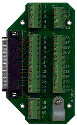
- CN1: 37‑pin D‑type female connector for relay outputs and digital inputs
- NO n = Normally Open contact of relay n
- NC n = Normally Closed contact of relay n
- COM n = Common contact of relay n
- DI n = Digital input channel n (non‑polarized)
6. Installation & Setup
Handling Precautions:
The PCM‑7250+ contains static‑sensitive components. Always handle the board using an anti‑static wrist strap and grounded mat.
Installation Steps:
1. Power off the host system and all peripherals.
2. Remove the system cover and locate an available PC/104‑Plus slot.
3. Set the rotary switch to match the module’s stack position (see Table below).
4. Configure input jumpers JP1–JP8 for AC‑filtered or DC input operation.
5. Insert the module into the PC/104‑Plus stack connector and secure with standoffs.
6. Reassemble the system and power on.
7. Install the ADLINK drivers from the included CD following the Software Installation Guide.
Rotary Switch Configuration (Bus Signal Assignment):
| Rotary Switch Position | Module Slot | CLK | IDSEL | INT | REQ | GNT |
|------------------------|-------------|------|--------|------|------|------|
| 0 or 4 | Slot 1 | CLK0 | IDSEL0 | INTA | REQ0* | GNT0* |
| 1 or 5 | Slot 2 | CLK1 | IDSEL1 | INTB | REQ1* | GNT1* |
| 2 or 6 | Slot 3 | CLK2 | IDSEL2 | INTC | REQ2* | GNT2* |
| 3 or 7 | Slot 4 | CLK3 | IDSEL3 | INTD | REQ2* | GNT2* |
*Slots 3 and 4 share REQ2/GNT2 and cannot both be bus masters.*
Input Signal Jumper Settings (JP1–JP8):
| Jumper | Channel | Non‑AC‑Filter (DC) | AC‑Filter (AC) |
|---------|----------|--------------------|----------------|
| JP1 | DI0 | 1–2 | 2–3 |
| JP2 | DI1 | 1–2 | 2–3 |
| JP3 | DI2 | 1–2 | 2–3 |
| JP4 | DI3 | 1–2 | 2–3 |
| JP5 | DI4 | 1–2 | 2–3 |
| JP6 | DI5 | 1–2 | 2–3 |
| JP7 | DI6 | 1–2 | 2–3 |
| JP8 | DI7 | 1–2 | 2–3 |
Connector Pin Assignments:
The CN1 connector provides all relay and input signals. Pin mapping corresponds to the PCI‑7250 layout, ensuring software and wiring compatibility.
7. Performance & Capabilities
- Relay Switching Speed: Typical operate/release 8 ms each.
- Contact Capacity: 0.5 A @ 120 VAC (resistive) or 1 A @ 24 V DC.
- Isolation: 5000 Vrms input‑to‑system; 1000 V AC/DC relay contact breakdown.
- Power Efficiency: Low power consumption (+5 V @ 140 mA idle).
- Reliability: > 10 million relay operations at rated load.
- Input Filtering: Selectable 5 ms time constant for AC inputs to reduce noise.
- System Capacity: Single module provides 8 relays and 8 inputs; multiple modules can be stacked for expanded I/O.
- Limitations: Relay contacts are rated for low‑power control signals; external power relays should be used for high‑current loads.
8. Standards & Compliance
- Bus Standard: PC/104‑Plus (PCI 2.1 compliant, 32‑bit)
- Electrical Isolation: 5000 Vrms input isolation per channel
- Safety & EMC: Designed for industrial environments with opto‑isolation and filtering to reduce EMI susceptibility
- Software Interface Standards: Compatible with OPC, ActiveX, DDE, and IEC 1131‑3 (ISaGRAF) standards
- Environmental Compliance: RoHS and lead‑free manufacturing process (typical for ADLINK industrial modules)
9. Additional Information
Warranty:
- Standard two‑year manufacturer’s warranty from shipment date.
- Covers defects in materials and workmanship.
- Excludes damage from improper installation, electrical overstress, or unauthorized repair.
- RMA procedure available via http://rma.adlinktech.com/policy.
Technical Support:
- Email: service@adlinktech.com
- Phone: +886‑2‑82265877
- Fax: +886‑2‑82265717
- Website: [www.adlinktech.com](http://www.adlinktech.com)
- Address: 9F, No. 166, Jian Yi Road, Chungho City, Taipei 235, Taiwan
Maintenance:
- Periodically inspect connectors and mounting hardware.
- Avoid exposure to excessive humidity or corrosive environments.
- Clean with dry compressed air only; do not use solvents.
Software Updates:
- Latest drivers and utilities available from ADLINK’s support portal.
- PCIS‑DASK and DAQ‑LVIEW PnP packages provide updated APIs for Windows and LabVIEW®.
Programming Support:
- C/C++ libraries for DOS and Windows 95/98/NT/2000/XP.
- Functions include initialization (_7250_Initial), digital input (_7250_DI), digital output (_7250_DO), and readback (_7250_DO_Read_Back).
- Compatible with Visual Basic and Delphi through DLL and ActiveX interfaces.
Relay Contact Protection:
ADLINK recommends using appropriate contact protection circuits to extend relay life and reduce EMF transients:
- RC Snubber Circuits for AC/DC loads.
- Diode or Zener Diode Circuits for DC inductive loads.
- Varistor Circuits for AC/DC applications requiring fast transient suppression.
Service Policy:
- Customer satisfaction is a priority; technical assistance is available via email or fax.
- Damaged products should be returned with an RMA form and proof of purchase.
Summary
The ADLINK PCM‑7250+ PC/104‑Plus 8‑Relay Module is a compact, high‑reliability digital I/O solution for embedded and industrial control systems. It integrates eight relays (four Form C and four Form A) and eight opto‑isolated inputs, providing robust electrical isolation and flexible signal interfacing. With jumper‑selectable input filtering, LED status indicators, and a rotary switch for bus configuration, the PCM‑7250+ offers ease of installation and adaptability within stackable PC/104‑Plus architectures.
Its comprehensive software support—including drivers for Windows and LabVIEW®, ActiveX controls, and OPC servers—makes it ideal for developers building custom automation and data acquisition systems. Designed for industrial environments, the module delivers long service life, high isolation, and stable operation across a wide temperature range, making it a reliable choice for embedded control applications requiring relay actuation and isolated digital input monitoring.


 SUCHEN SIE DIE PASSENDE
 LPCI-7250_Manual_2.pdf
Manual
LPCI-7250_Manual_2.pdf
Manual
 Appendix_PCM-7250.pdf
Manual
Appendix_PCM-7250.pdf
Manual