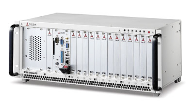
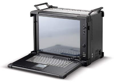
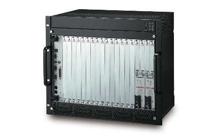
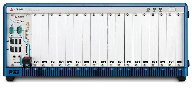
PXIS Spare Fan
SUCHEN SIE DIE PASSENDE
INDUSTRIELLE LÖSUNG?
Entdecken Sie Embedded-, Kommunikations- und Automatisierungslösungen für Ihre Anwendung.
- 14‑Slot Architecture: One system controller slot and thirteen PXI/CompactPCI peripheral slots.
- PXI Specification Rev. 2.2 Compliance: Supports PXI features such as 10 MHz reference clock, trigger bus, local bus, and star trigger routing.
- Compact 3U Design: 483 mm (W) × 178 mm (H) × 258 mm (D) chassis optimized for rackmount or benchtop use.
- Industrial‑Grade 500 W Power Supply: 2U ATX AC power supply with 100–240 V AC input range and full‑load output of 500 W.
- Hot‑Swappable Cooling Fans: Five front‑accessible 80 × 80 × 15 mm ball‑bearing fans (31 CFM each) for continuous operation and reduced MTTR.
- Comprehensive System Monitoring: Front‑panel LEDs and buzzer alarm for voltage, temperature, and fan status.
- Filtered Forced‑Air Cooling: Bottom‑mounted fan trays with removable air filters ensure efficient airflow and easy maintenance.
- PXI/CompactPCI Interoperability: Fully compatible with both PXI and CompactPCI 32‑bit/33 MHz and 64‑bit/66 MHz modules.
- Star Trigger and Local Bus Support: Dedicated trigger lines and local bus interconnections for synchronized multi‑module operation.
- OEM Customization Options: Configurable power supply (AC/DC), chassis color, and logo branding available for OEM applications.
- PXI Specification Rev. 2.2 Compliance: Supports PXI features such as 10 MHz reference clock, trigger bus, local bus, and star trigger routing.
- Compact 3U Design: 483 mm (W) × 178 mm (H) × 258 mm (D) chassis optimized for rackmount or benchtop use.
- Industrial‑Grade 500 W Power Supply: 2U ATX AC power supply with 100–240 V AC input range and full‑load output of 500 W.
- Hot‑Swappable Cooling Fans: Five front‑accessible 80 × 80 × 15 mm ball‑bearing fans (31 CFM each) for continuous operation and reduced MTTR.
- Comprehensive System Monitoring: Front‑panel LEDs and buzzer alarm for voltage, temperature, and fan status.
- Filtered Forced‑Air Cooling: Bottom‑mounted fan trays with removable air filters ensure efficient airflow and easy maintenance.
- PXI/CompactPCI Interoperability: Fully compatible with both PXI and CompactPCI 32‑bit/33 MHz and 64‑bit/66 MHz modules.
- Star Trigger and Local Bus Support: Dedicated trigger lines and local bus interconnections for synchronized multi‑module operation.
- OEM Customization Options: Configurable power supply (AC/DC), chassis color, and logo branding available for OEM applications.
Comprehensive Product Summary: ADLINK PXIS‑2670 PXI/cPCI 3U Chassis
### 1. Product Overview
Product Name: PXIS‑2670
Model Number: PXIS‑2670
Series: PXIS‑2600 Series
Article Number: PXIS‑2670
Manufacturer: ADLINK Technology Inc.
Product Type: PXI/CompactPCI 3U Instrument Chassis
Form Factor: 19‑inch rackmount, 3U height
Country of Origin: Taiwan
The ADLINK PXIS‑2670 is a 14‑slot PXI/CompactPCI chassis designed for modular test, measurement, and automation systems. It integrates one system controller slot and thirteen peripheral slots within a compact 3U enclosure, providing a robust, high‑performance platform for PXI and CompactPCI instrumentation modules. The chassis is fully compliant with PXI Specification Revision 2.2 and IEEE 1101.10 mechanical standards, ensuring interoperability with a wide range of PXI and CompactPCI modules.
### 2. Key Features
- 14‑Slot Architecture: One system controller slot and thirteen PXI/CompactPCI peripheral slots.
- PXI Specification Rev. 2.2 Compliance: Supports PXI features such as 10 MHz reference clock, trigger bus, local bus, and star trigger routing.
- Compact 3U Design: 483 mm (W) × 178 mm (H) × 258 mm (D) chassis optimized for rackmount or benchtop use.
- Industrial‑Grade 500 W Power Supply: 2U ATX AC power supply with 100–240 V AC input range and full‑load output of 500 W.
- Hot‑Swappable Cooling Fans: Five front‑accessible 80 × 80 × 15 mm ball‑bearing fans (31 CFM each) for continuous operation and reduced MTTR.
- Comprehensive System Monitoring: Front‑panel LEDs and buzzer alarm for voltage, temperature, and fan status.
- Filtered Forced‑Air Cooling: Bottom‑mounted fan trays with removable air filters ensure efficient airflow and easy maintenance.
- PXI/CompactPCI Interoperability: Fully compatible with both PXI and CompactPCI 32‑bit/33 MHz and 64‑bit/66 MHz modules.
- Star Trigger and Local Bus Support: Dedicated trigger lines and local bus interconnections for synchronized multi‑module operation.
- OEM Customization Options: Configurable power supply (AC/DC), chassis color, and logo branding available for OEM applications.
### 3. Technical Specifications
Physical Characteristics
- Slots: 14 total (1 system slot + 13 peripheral slots)
- Controller Expansion Slots: 3 (left of system slot)
- Dimensions (W × H × D): 483 mm × 178 mm × 258 mm (without handles)
- Weight: 14 kg (30.8 lb)
- Material: Aluminum alloy chassis with steel frame, UL 94V‑0 rated backplane
Power Supply
- Type: 2U ATX industrial‑grade AC power supply
- Input Voltage: 100 – 240 V AC ± 10%
- Input Frequency: 50 – 60 Hz ± 5%
- Output Power: 500 W total
- DC Output Rails:
- +5 V @ 50 A (max)
- +3.3 V @ 28 A (max)
- +12 V @ 35 A (max)
- −12 V @ 0.8 A (max)
- Combined +5 V and +3.3 V Output: ≤ 250 W
Cooling System
- Fans: Five 80 × 80 × 15 mm ball‑bearing fans, 31 CFM each
- Fan Speed: 2900 ± 300 RPM
- Noise Level: 36 dB(A)
- Power per Fan: 12 V DC @ 0.17 A
- Air Filter: Removable, bottom‑mounted
- Cooling Method: Filtered, forced‑air front‑to‑rear airflow
Environmental Conditions
- Operating Temperature: 0 °C – 50 °C
- Storage Temperature: −20 °C – 70 °C
- Operating Humidity: 10 % – 90 % RH, non‑condensing
- Storage Humidity: 5 % – 95 % RH, non‑condensing
Shock and Vibration
- Shock Resistance: 15 G peak‑to‑peak, 11 ms duration
- Vibration (Operating): 5 – 500 Hz, 0.5 G RMS per axis
- Vibration (Non‑Operating): 5 – 500 Hz, 1.88 G RMS per axis
### 4. Functionality
The PXIS‑2670 serves as the mechanical and electrical foundation for PXI‑based test and measurement systems. It distributes power, clock, and trigger signals to all installed modules through its 14‑slot backplane (model xBP‑3014L). The chassis supports both PXI and CompactPCI modules, enabling flexible system configuration for data acquisition, signal analysis, and control applications.
Operational Features:
- System Slot (Slot 1): Hosts the PXI system controller (e.g., ADLINK PXI‑3900 series).
- Star Trigger Slot (Slot 2): Provides dedicated trigger lines (PXI_STAR0 – PXI_STAR11) for precise synchronization.
- Peripheral Slots (Slots 3 – 14): Accommodate measurement, I/O, or communication modules.
- Local Bus: 13‑line daisy‑chain interconnect between adjacent peripheral slots for high‑speed sideband communication.
- Trigger Bus: Enables synchronized triggering across modules for coordinated measurement sequences.
- 10 MHz Reference Clock: Distributed to all slots with < 1 ns skew; selectable internal or external source via jumper JP2.
Applications:
- Automated test equipment (ATE)
- Data acquisition and signal processing
- Industrial and transportation control systems
- Communication signal analysis
- Research and laboratory instrumentation
Compatibility:
- PXI Specification Rev. 2.2
- CompactPCI (PICMG 2.0)
- IEEE 1101.10 mechanical standard
- Compatible with ADLINK PXI‑3800, PXI‑3710, PXI‑3710F, and PXI‑3900 controllers
### 5. Components & Accessories
Included Items:
- PXIS‑2670 chassis with integrated 500 W AC power supply
- Power cord
- User’s manual (Part No. 50‑17022‑1000)
Optional Accessories:
- PXIS Spare Fan Kit (for PXIS‑2600 and PXIS‑2700 series)
- Redundant AC/DC CompactPCI power supply modules (OEM option)
- Custom chassis color and logo branding (OEM option)
Connectors and Interfaces:
- CN1/CN2: ATX DC power input connectors
- J1: INH# (DC power inhibit)
- J2: FAL# (power supply fail input)
- J3: PRST# (system reset)
- J4: LED power status connector (+3.3 V, +5 V, ±12 V indicators)
- CN5: SMBus connector (IPMB_CLK, IPMB_DATA, IPMB_PWR, ALERT)
- JP2: 10 MHz reference clock source selector (internal/external)
- JP3: Bus speed control (33 MHz forced or M66EN auto‑detect)
### 6. Installation & Setup
Requirements:
- AC power source 100–240 V AC, 50–60 Hz
- Proper grounding of mounting holes (GND and FGND options)
- Adequate ventilation space around the chassis
Installation Steps:
1. Ensure the power switch is OFF.
2. Connect the AC power cord to a grounded outlet.
3. Install the system controller in Slot 1 using the red card guide and secure with screws.
4. Insert peripheral modules into available slots.
5. Power ON the chassis and verify LED indicators (+3.3 V, +5 V, ±12 V green LEDs ON).
6. Confirm fan operation and monitor LED status for temperature and fan speed.
System Monitoring Indicators:
- Power LEDs: Green (+3.3 V, +5 V, +12 V, −12 V) – ON when voltage present.
- Temperature LED: Amber – ON (normal), flashing (over‑temperature).
- Fan LED: Green – ON (normal speed), flashing (abnormal speed).
- Alarm LED: Red – flashing when fault detected.
- Alarm Buzzer: Audible alert for any fault; reset via Alarm RST button.
Grounding Configuration:
- Mounting holes labeled “GND” connect to logic ground.
- Mounting holes labeled “FGND” provide chassis isolation.
- For isolated operation, remove screws from GND holes.
### 7. Performance & Capabilities
Electrical Performance:
- Stable 500 W output with tight voltage regulation across all rails.
- Supports high‑current PXI modules requiring up to 50 A on +5 V rail.
- Efficient power distribution through low‑impedance backplane design.
Cooling Efficiency:
- Five 31 CFM fans provide > 150 CFM total airflow.
- Hot‑swappable design minimizes downtime and reduces MTTR.
- Temperature thresholds configurable at 50 °C, 60 °C, or 70 °C (default 50 °C).
System Synchronization:
- 10 MHz reference clock with < 1 ns skew between slots.
- PXI trigger bus and star trigger enable precise timing control across modules.
- Local bus supports high‑speed analog or digital sideband communication.
Limitations:
- Maximum ambient operating temperature 50 °C.
- Combined +5 V and +3.3 V output limited to 250 W.
- Designed for indoor laboratory or industrial environments only.
### 8. Standards & Compliance
PXI and CompactPCI Standards:
- PXI Specification Revision 2.2
- CompactPCI Specification (PICMG 2.0)
- IEEE 1101.10 mechanical packaging
Safety and EMC Compliance:
- Safety: EN 60950‑1
- EMC Emissions: EN 55022, FCC Class A
- EMC Immunity: EN 55024
- CE Marking: Compliant
- Backplane Materials: UL 94V‑0 rated
Environmental and Reliability Standards:
- Designed for industrial operation (0 – 50 °C, 10 – 90 % RH)
- Shock and vibration tested to 15 G and 0.5 G RMS respectively
### 9. Additional Information
Warranty:
- Standard two‑year limited warranty (one year for China).
- Warranty covers manufacturing defects and hardware failures under normal use.
- Exclusions include damage from misuse, improper storage, unauthorized repair, or acts of God.
- Customers must obtain an RMA number before returning products for service.
Maintenance:
- Interior Cleaning: Use dry air or 75 % isopropyl alcohol solution; power off before servicing.
- Exterior Cleaning: Wipe with lint‑free cloth and mild soap solution; avoid abrasives.
- Fan Replacement: Front‑panel access; press Alarm RST, remove fan tray, replace unit, reinstall cover.
- Temperature Monitoring: Amber LED flashes and buzzer beeps if temperature exceeds threshold.
Support and Service:
- Manufacturer: ADLINK Technology Inc.
- Address: 9F, No. 166, Jian Yi Road, Chungho City, Taipei 235, Taiwan
- Telephone: +886‑2‑8226‑5877
- Fax: +886‑2‑8226‑5717
- Email: service@adlinktech.com
- Website: [www.adlinktech.com](http://www.adlinktech.com)
Recommended System Controllers:
- ADLINK PXI‑3900 Series Controllers
- ADLINK PXI‑3800 / PXI‑3710 / PXI‑3710F Controllers
Ordering Information:
- PXIS‑2670: 14‑Slot 3U PXI/CompactPCI Chassis with 500 W AC Power Supply
- PXIS Spare Fan: Replacement fan module for PXIS‑2600 and PXIS‑2700 series
Revision History:
- User’s Manual Revision: 2.01 (December 21, 2006)
- Document Update: March 28, 2012
- Part Number: 50‑17022‑1000
### Summary
The ADLINK PXIS‑2670 is a high‑reliability, 14‑slot PXI/CompactPCI chassis engineered for demanding test and measurement environments. Its compact 3U form factor, robust 500 W power supply, and advanced thermal management make it ideal for laboratory, industrial, and OEM applications requiring stable power, precise timing, and modular scalability. With full PXI 2.2 compliance, hot‑swappable cooling, and comprehensive system monitoring, the PXIS‑2670 delivers exceptional performance, maintainability, and interoperability within PXI‑based instrumentation systems.

### 1. Product Overview
Product Name: PXIS‑2670
Model Number: PXIS‑2670
Series: PXIS‑2600 Series
Article Number: PXIS‑2670
Manufacturer: ADLINK Technology Inc.
Product Type: PXI/CompactPCI 3U Instrument Chassis
Form Factor: 19‑inch rackmount, 3U height
Country of Origin: Taiwan
The ADLINK PXIS‑2670 is a 14‑slot PXI/CompactPCI chassis designed for modular test, measurement, and automation systems. It integrates one system controller slot and thirteen peripheral slots within a compact 3U enclosure, providing a robust, high‑performance platform for PXI and CompactPCI instrumentation modules. The chassis is fully compliant with PXI Specification Revision 2.2 and IEEE 1101.10 mechanical standards, ensuring interoperability with a wide range of PXI and CompactPCI modules.
### 2. Key Features
- 14‑Slot Architecture: One system controller slot and thirteen PXI/CompactPCI peripheral slots.
- PXI Specification Rev. 2.2 Compliance: Supports PXI features such as 10 MHz reference clock, trigger bus, local bus, and star trigger routing.
- Compact 3U Design: 483 mm (W) × 178 mm (H) × 258 mm (D) chassis optimized for rackmount or benchtop use.
- Industrial‑Grade 500 W Power Supply: 2U ATX AC power supply with 100–240 V AC input range and full‑load output of 500 W.
- Hot‑Swappable Cooling Fans: Five front‑accessible 80 × 80 × 15 mm ball‑bearing fans (31 CFM each) for continuous operation and reduced MTTR.
- Comprehensive System Monitoring: Front‑panel LEDs and buzzer alarm for voltage, temperature, and fan status.
- Filtered Forced‑Air Cooling: Bottom‑mounted fan trays with removable air filters ensure efficient airflow and easy maintenance.
- PXI/CompactPCI Interoperability: Fully compatible with both PXI and CompactPCI 32‑bit/33 MHz and 64‑bit/66 MHz modules.
- Star Trigger and Local Bus Support: Dedicated trigger lines and local bus interconnections for synchronized multi‑module operation.
- OEM Customization Options: Configurable power supply (AC/DC), chassis color, and logo branding available for OEM applications.
### 3. Technical Specifications
Physical Characteristics
- Slots: 14 total (1 system slot + 13 peripheral slots)
- Controller Expansion Slots: 3 (left of system slot)
- Dimensions (W × H × D): 483 mm × 178 mm × 258 mm (without handles)
- Weight: 14 kg (30.8 lb)
- Material: Aluminum alloy chassis with steel frame, UL 94V‑0 rated backplane
Power Supply
- Type: 2U ATX industrial‑grade AC power supply
- Input Voltage: 100 – 240 V AC ± 10%
- Input Frequency: 50 – 60 Hz ± 5%
- Output Power: 500 W total
- DC Output Rails:
- +5 V @ 50 A (max)
- +3.3 V @ 28 A (max)
- +12 V @ 35 A (max)
- −12 V @ 0.8 A (max)
- Combined +5 V and +3.3 V Output: ≤ 250 W
Cooling System
- Fans: Five 80 × 80 × 15 mm ball‑bearing fans, 31 CFM each
- Fan Speed: 2900 ± 300 RPM
- Noise Level: 36 dB(A)
- Power per Fan: 12 V DC @ 0.17 A
- Air Filter: Removable, bottom‑mounted
- Cooling Method: Filtered, forced‑air front‑to‑rear airflow
Environmental Conditions
- Operating Temperature: 0 °C – 50 °C
- Storage Temperature: −20 °C – 70 °C
- Operating Humidity: 10 % – 90 % RH, non‑condensing
- Storage Humidity: 5 % – 95 % RH, non‑condensing
Shock and Vibration
- Shock Resistance: 15 G peak‑to‑peak, 11 ms duration
- Vibration (Operating): 5 – 500 Hz, 0.5 G RMS per axis
- Vibration (Non‑Operating): 5 – 500 Hz, 1.88 G RMS per axis
### 4. Functionality
The PXIS‑2670 serves as the mechanical and electrical foundation for PXI‑based test and measurement systems. It distributes power, clock, and trigger signals to all installed modules through its 14‑slot backplane (model xBP‑3014L). The chassis supports both PXI and CompactPCI modules, enabling flexible system configuration for data acquisition, signal analysis, and control applications.
Operational Features:
- System Slot (Slot 1): Hosts the PXI system controller (e.g., ADLINK PXI‑3900 series).
- Star Trigger Slot (Slot 2): Provides dedicated trigger lines (PXI_STAR0 – PXI_STAR11) for precise synchronization.
- Peripheral Slots (Slots 3 – 14): Accommodate measurement, I/O, or communication modules.
- Local Bus: 13‑line daisy‑chain interconnect between adjacent peripheral slots for high‑speed sideband communication.
- Trigger Bus: Enables synchronized triggering across modules for coordinated measurement sequences.
- 10 MHz Reference Clock: Distributed to all slots with < 1 ns skew; selectable internal or external source via jumper JP2.
Applications:
- Automated test equipment (ATE)
- Data acquisition and signal processing
- Industrial and transportation control systems
- Communication signal analysis
- Research and laboratory instrumentation
Compatibility:
- PXI Specification Rev. 2.2
- CompactPCI (PICMG 2.0)
- IEEE 1101.10 mechanical standard
- Compatible with ADLINK PXI‑3800, PXI‑3710, PXI‑3710F, and PXI‑3900 controllers
### 5. Components & Accessories
Included Items:
- PXIS‑2670 chassis with integrated 500 W AC power supply
- Power cord
- User’s manual (Part No. 50‑17022‑1000)
Optional Accessories:
- PXIS Spare Fan Kit (for PXIS‑2600 and PXIS‑2700 series)
- Redundant AC/DC CompactPCI power supply modules (OEM option)
- Custom chassis color and logo branding (OEM option)
Connectors and Interfaces:
- CN1/CN2: ATX DC power input connectors
- J1: INH# (DC power inhibit)
- J2: FAL# (power supply fail input)
- J3: PRST# (system reset)
- J4: LED power status connector (+3.3 V, +5 V, ±12 V indicators)
- CN5: SMBus connector (IPMB_CLK, IPMB_DATA, IPMB_PWR, ALERT)
- JP2: 10 MHz reference clock source selector (internal/external)
- JP3: Bus speed control (33 MHz forced or M66EN auto‑detect)
### 6. Installation & Setup
Requirements:
- AC power source 100–240 V AC, 50–60 Hz
- Proper grounding of mounting holes (GND and FGND options)
- Adequate ventilation space around the chassis
Installation Steps:
1. Ensure the power switch is OFF.
2. Connect the AC power cord to a grounded outlet.
3. Install the system controller in Slot 1 using the red card guide and secure with screws.
4. Insert peripheral modules into available slots.
5. Power ON the chassis and verify LED indicators (+3.3 V, +5 V, ±12 V green LEDs ON).
6. Confirm fan operation and monitor LED status for temperature and fan speed.
System Monitoring Indicators:
- Power LEDs: Green (+3.3 V, +5 V, +12 V, −12 V) – ON when voltage present.
- Temperature LED: Amber – ON (normal), flashing (over‑temperature).
- Fan LED: Green – ON (normal speed), flashing (abnormal speed).
- Alarm LED: Red – flashing when fault detected.
- Alarm Buzzer: Audible alert for any fault; reset via Alarm RST button.
Grounding Configuration:
- Mounting holes labeled “GND” connect to logic ground.
- Mounting holes labeled “FGND” provide chassis isolation.
- For isolated operation, remove screws from GND holes.
### 7. Performance & Capabilities
Electrical Performance:
- Stable 500 W output with tight voltage regulation across all rails.
- Supports high‑current PXI modules requiring up to 50 A on +5 V rail.
- Efficient power distribution through low‑impedance backplane design.
Cooling Efficiency:
- Five 31 CFM fans provide > 150 CFM total airflow.
- Hot‑swappable design minimizes downtime and reduces MTTR.
- Temperature thresholds configurable at 50 °C, 60 °C, or 70 °C (default 50 °C).
System Synchronization:
- 10 MHz reference clock with < 1 ns skew between slots.
- PXI trigger bus and star trigger enable precise timing control across modules.
- Local bus supports high‑speed analog or digital sideband communication.
Limitations:
- Maximum ambient operating temperature 50 °C.
- Combined +5 V and +3.3 V output limited to 250 W.
- Designed for indoor laboratory or industrial environments only.
### 8. Standards & Compliance
PXI and CompactPCI Standards:
- PXI Specification Revision 2.2
- CompactPCI Specification (PICMG 2.0)
- IEEE 1101.10 mechanical packaging
Safety and EMC Compliance:
- Safety: EN 60950‑1
- EMC Emissions: EN 55022, FCC Class A
- EMC Immunity: EN 55024
- CE Marking: Compliant
- Backplane Materials: UL 94V‑0 rated
Environmental and Reliability Standards:
- Designed for industrial operation (0 – 50 °C, 10 – 90 % RH)
- Shock and vibration tested to 15 G and 0.5 G RMS respectively
### 9. Additional Information
Warranty:
- Standard two‑year limited warranty (one year for China).
- Warranty covers manufacturing defects and hardware failures under normal use.
- Exclusions include damage from misuse, improper storage, unauthorized repair, or acts of God.
- Customers must obtain an RMA number before returning products for service.
Maintenance:
- Interior Cleaning: Use dry air or 75 % isopropyl alcohol solution; power off before servicing.
- Exterior Cleaning: Wipe with lint‑free cloth and mild soap solution; avoid abrasives.
- Fan Replacement: Front‑panel access; press Alarm RST, remove fan tray, replace unit, reinstall cover.
- Temperature Monitoring: Amber LED flashes and buzzer beeps if temperature exceeds threshold.
Support and Service:
- Manufacturer: ADLINK Technology Inc.
- Address: 9F, No. 166, Jian Yi Road, Chungho City, Taipei 235, Taiwan
- Telephone: +886‑2‑8226‑5877
- Fax: +886‑2‑8226‑5717
- Email: service@adlinktech.com
- Website: [www.adlinktech.com](http://www.adlinktech.com)
Recommended System Controllers:
- ADLINK PXI‑3900 Series Controllers
- ADLINK PXI‑3800 / PXI‑3710 / PXI‑3710F Controllers
Ordering Information:
- PXIS‑2670: 14‑Slot 3U PXI/CompactPCI Chassis with 500 W AC Power Supply
- PXIS Spare Fan: Replacement fan module for PXIS‑2600 and PXIS‑2700 series
Revision History:
- User’s Manual Revision: 2.01 (December 21, 2006)
- Document Update: March 28, 2012
- Part Number: 50‑17022‑1000
### Summary
The ADLINK PXIS‑2670 is a high‑reliability, 14‑slot PXI/CompactPCI chassis engineered for demanding test and measurement environments. Its compact 3U form factor, robust 500 W power supply, and advanced thermal management make it ideal for laboratory, industrial, and OEM applications requiring stable power, precise timing, and modular scalability. With full PXI 2.2 compliance, hot‑swappable cooling, and comprehensive system monitoring, the PXIS‑2670 delivers exceptional performance, maintainability, and interoperability within PXI‑based instrumentation systems.

-
PXIS-2670_Datasheet_en_1.pdf
PDF Catalog
-
PXIS-2670_Manual_4.pdf
Manual
- PXIS Spare Fan - PXIS Chassis Spare Fan for PXIS-2700 & PXIS-2600