DIN-RAIL-R
SUCHEN SIE DIE PASSENDE
INDUSTRIELLE LÖSUNG?
Entdecken Sie Embedded-, Kommunikations- und Automatisierungslösungen für Ihre Anwendung.
- 8 Isolated Analog Input Channels: Each channel supports voltage or current input with configurable ranges (±650 mV, ±1.25 V, ±2.5 V, ±5 V, ±10 V, ±20 mA).
- High‑Resolution Conversion: 24‑bit resolution at 10 samples/s (Normal Mode) or 16‑bit resolution at 60 samples/s (Fast Mode).
- Wide Communication Range: RS‑485 interface supporting baud rates from 1.2 kbps to 115.2 kbps.
- Protocol Flexibility: Supports both ASCII and Modbus RTU communication protocols for easy integration with PLCs, SCADA, and PC‑based systems.
- Electrical Isolation: 3750 Vrms photo‑isolation between analog and digital sections ensures protection against ground loops and high‑voltage transients.
- Surge Protection: Built‑in surge protection on RS‑485 data lines safeguards against electrical spikes.
- Dual Watchdog System: Hardware and host watchdogs ensure continuous operation and automatic recovery from communication or system faults.
- Auto and Manual Calibration: Automatic voltage calibration at power‑up; manual calibration commands available for zero and full‑scale adjustments.
- LED Indicators: Power and communication status LEDs for visual diagnostics.
- Flexible Mounting: Supports both DIN‑rail and panel mounting.
- Wide Power Supply Range: Operates from +10 V DC to +30 V DC.
- Compact and Rugged Design: Industrial‑grade enclosure with screw terminal connections for secure wiring.
- High‑Resolution Conversion: 24‑bit resolution at 10 samples/s (Normal Mode) or 16‑bit resolution at 60 samples/s (Fast Mode).
- Wide Communication Range: RS‑485 interface supporting baud rates from 1.2 kbps to 115.2 kbps.
- Protocol Flexibility: Supports both ASCII and Modbus RTU communication protocols for easy integration with PLCs, SCADA, and PC‑based systems.
- Electrical Isolation: 3750 Vrms photo‑isolation between analog and digital sections ensures protection against ground loops and high‑voltage transients.
- Surge Protection: Built‑in surge protection on RS‑485 data lines safeguards against electrical spikes.
- Dual Watchdog System: Hardware and host watchdogs ensure continuous operation and automatic recovery from communication or system faults.
- Auto and Manual Calibration: Automatic voltage calibration at power‑up; manual calibration commands available for zero and full‑scale adjustments.
- LED Indicators: Power and communication status LEDs for visual diagnostics.
- Flexible Mounting: Supports both DIN‑rail and panel mounting.
- Wide Power Supply Range: Operates from +10 V DC to +30 V DC.
- Compact and Rugged Design: Industrial‑grade enclosure with screw terminal connections for secure wiring.
Comprehensive Product Summary: TRP‑C68 Isolated 8‑Channel Analog Input RS‑485 Modbus RTU Module
### 1. Product Overview
Product Name: TRP‑C68
Model: TRP‑C68
Series: TRP‑C Industrial Communication Modules
Article Number: TRP‑C68
Manufacturer: Trycom Technology Co., Ltd.
Manufacturer Address: No. 35, Zhongxing Rd., Guishan Township, Taoyuan County 333, Taiwan
Contact: Tel: +886‑3‑350‑3351 | Fax: +886‑3‑350‑3352
Website: [www.trycom.com.tw](http://www.trycom.com.tw)
Product Description:
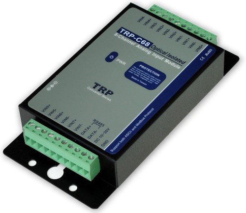
The TRP‑C68 is an isolated 8‑channel analog input (AI) to digital output (DO) converter module designed for industrial data acquisition and control systems. It converts analog voltage or current signals into digital data and communicates via RS‑485 using either ASCII or Modbus RTU protocols. The module provides high‑resolution 24‑bit or 16‑bit sampling, robust 3750 Vrms isolation, surge protection, and flexible configuration options for integration into distributed control networks.
### 2. Key Features
- 8 Isolated Analog Input Channels: Each channel supports voltage or current input with configurable ranges (±650 mV, ±1.25 V, ±2.5 V, ±5 V, ±10 V, ±20 mA).
- High‑Resolution Conversion: 24‑bit resolution at 10 samples/s (Normal Mode) or 16‑bit resolution at 60 samples/s (Fast Mode).
- Wide Communication Range: RS‑485 interface supporting baud rates from 1.2 kbps to 115.2 kbps.
- Protocol Flexibility: Supports both ASCII and Modbus RTU communication protocols for easy integration with PLCs, SCADA, and PC‑based systems.
- Electrical Isolation: 3750 Vrms photo‑isolation between analog and digital sections ensures protection against ground loops and high‑voltage transients.
- Surge Protection: Built‑in surge protection on RS‑485 data lines safeguards against electrical spikes.
- Dual Watchdog System: Hardware and host watchdogs ensure continuous operation and automatic recovery from communication or system faults.
- Auto and Manual Calibration: Automatic voltage calibration at power‑up; manual calibration commands available for zero and full‑scale adjustments.
- LED Indicators: Power and communication status LEDs for visual diagnostics.
- Flexible Mounting: Supports both DIN‑rail and panel mounting.
- Wide Power Supply Range: Operates from +10 V DC to +30 V DC.
- Compact and Rugged Design: Industrial‑grade enclosure with screw terminal connections for secure wiring.
### 3. Technical Specifications
| Parameter | Specification |
|----------------|-------------------|
| Analog Input Channels | 8 differential, isolated |
| Input Type | Voltage or current |
| Voltage Input Ranges | ±10 V, ±5 V, ±2.5 V, ±1.25 V, ±650 mV |
| Current Input Range | ±20 mA |
| Resolution | 24 bit (Normal Mode), 16 bit (Fast Mode) |
| Sampling Rate | 10 samples/s (24 bit), 60 samples/s (16 bit) |
| Bandwidth | 15.72 Hz (Normal), 78.72 Hz (Fast) |
| Accuracy | ±0.1 % (Normal), ±0.5 % (Fast) |
| Zero Drift | 0.03 µV/°C |
| Span Drift | 25 ppm/°C |
| Common‑Mode Rejection Ratio (CMRR) | ≥ 92 dB at 50/60 Hz |
| Over‑Voltage Protection | ±35 V |
| Isolation Voltage | 3750 Vrms between analog and digital circuits |
| Communication Interface | RS‑485, 2‑wire |
| Communication Distance | Up to 1200 m (4000 ft) |
| Baud Rate Range | 1.2 kbps – 115.2 kbps |
| Power Supply | +10 V DC – +30 V DC |
| Power Consumption | 1.2 W |
| Indicators | Power LED, Communication LED |
| Operating Temperature | 0 °C – 60 °C |
| Storage Temperature | −20 °C – 70 °C |
| Humidity | 10 % – 90 % RH, non‑condensing |
| Dimensions | 151 mm × 75 mm × 26 mm |
| Weight | 398 – 400 g |
| Connection Type | Screw terminal, accepts AWG #12 – #32 wires |
| Mounting Options | DIN‑rail or panel mount |
### 4. Functionality
Operating Principle:
The TRP‑C68 functions as an analog‑to‑digital converter (ADC) module. It receives analog voltage or current signals from sensors or transducers, converts them into digital data, and transmits the data via RS‑485 to a host controller or PC. The module can operate in either ASCII or Modbus RTU mode, selectable via an external DIP switch.
Use Cases and Applications:
- Industrial process monitoring and control
- Data acquisition systems (DAQ)
- SCADA and PLC integration
- Remote analog signal measurement over RS‑485 networks
- Laboratory instrumentation and calibration systems
- Energy management and environmental monitoring
Compatibility:
Compatible with Modbus RTU/ASCII master devices, PLCs, industrial PCs, and Trycom’s TRPCOM configuration utility. It can also be tested using Modbus Poll software for Modbus RTU communication verification.
### 5. Components & Accessories
Included Components:
- TRP‑C68 module unit
- Screw terminal connectors for analog input and RS‑485 interface
- External DC power input terminal
- User manual and configuration guide
- TRPCOM configuration utility (on support CD or downloadable)
Optional Accessories:
- External DC power adapter (10–30 V DC)
- DIN‑rail mounting kit
- RS‑485 communication cables
- Modbus Poll or third‑party Modbus diagnostic software
Connectors and Pin Assignments:
- Analog Inputs (VIN0 – VIN7): Differential pairs (+/−) for each channel
- RS‑485 Data Lines: DATA+ and DATA− terminals
- Power Input: DC 10–30 V and GND terminals
Example pin mapping:
```
VIN0+ / VIN0− → Channel 0 input
VIN1+ / VIN1− → Channel 1 input
...
VIN7+ / VIN7− → Channel 7 input
DATA+ / DATA− → RS‑485 communication lines
DC 10–30 V / GND → Power input
```
### 6. Installation & Setup
Power Requirements:
Supply voltage between +10 V DC and +30 V DC. Power can be connected via screw terminal or external DC adapter.
Mounting Options:
Supports both DIN‑rail and panel mounting for flexible installation in control cabinets or equipment racks.
Configuration:
- DIP Switch Settings:
- Select communication protocol (ASCII or Modbus RTU).
- “Back to INIT” function resets module ID, baud rate, and data format to factory defaults.
- Default settings:
- ID = 01
- Baud Rate = 9600 bps
- Analog Mode = ±10 V
- Data Format = 00 (Voltage)
- Checksum = Disabled
- RS‑485 format = N, 8, 1
Wiring Guidelines:
- Use twisted‑pair shielded cable for RS‑485 communication.
- Maintain proper grounding and isolation to prevent noise interference.
- Maximum communication distance: 1200 m (4000 ft).
- Terminate RS‑485 lines appropriately for long‑distance installations.
Software Configuration:
- Use TRPCOM Utility for Windows to configure module ID, baud rate, data format, and analog input type.
- The utility provides online scanning, configuration, and real‑time data monitoring.
- Alternatively, use Modbus Poll software for Modbus RTU testing and data verification.
### 7. Performance & Capabilities
Sampling and Conversion:
- Normal Mode: 24‑bit resolution, 10 samples/s, 15.72 Hz bandwidth.
- Fast Mode: 16‑bit resolution, 60 samples/s, 78.72 Hz bandwidth.
- Accuracy: ±0.1 % (Normal), ±0.5 % (Fast).
- CMRR: ≥ 92 dB ensures high noise immunity.
Communication Performance:
- RS‑485 half‑duplex, 2‑wire interface.
- Baud rates selectable from 1200 bps to 115200 bps.
- Transmission distance up to 1200 m (4000 ft).
- Supports ASCII and Modbus RTU protocols with CRC error checking.
Reliability Features:
- Dual Watchdog System:
- *Module Watchdog:* Hardware reset circuit ensures continuous operation under noise or fault conditions.
- *Host Watchdog:* Software timer monitors communication; if timeout occurs, outputs revert to safe state.
- Auto Reset: Automatic recovery from communication or voltage anomalies.
- Auto Calibration: Voltage calibration performed at power‑up; manual calibration commands available for fine adjustment.
Limitations:
- Analog input limited to ±35 V protection threshold.
- Operating temperature range restricted to 0–60 °C; not suitable for extreme environments without enclosure protection.
- RS‑485 communication limited to 1200 m without repeaters.
### 8. Standards & Compliance
Electrical and Safety Standards:
- 3750 Vrms isolation between analog and digital circuits.
- Surge protection on RS‑485 data lines.
- Designed for industrial EMC environments.
Communication Standards:
- Complies with Modbus RTU and Modbus ASCII protocol specifications.
- RS‑485 interface conforms to EIA/TIA‑485 standard.
Environmental Compliance:
- Operating humidity 10–90 % non‑condensing.
- RoHS‑compliant manufacturing (lead‑free components).
Quality and Reliability:
- Manufactured under Trycom’s ISO‑certified quality management system.
- Each unit tested for isolation, accuracy, and communication integrity.
### 9. Additional Information
Warranty:
Standard manufacturer warranty (typically one year) covering defects in materials and workmanship. Warranty terms subject to Trycom’s policy at time of purchase.
Technical Support:
Trycom provides technical documentation, firmware updates, and configuration utilities via its website. Support is available through email or phone.
Maintenance:
- Periodic inspection of wiring and terminal connections recommended.
- Ensure proper grounding and surge protection in high‑noise environments.
- Firmware updates can be applied via RS‑485 communication interface when available.
Firmware and Software Updates:
- Firmware version and release date can be read using Modbus or ASCII commands (`$IDF`).
- Example: Response “!01C68M070407” indicates firmware version dated 2007‑04‑07.
- TRPCOM utility updates available from Trycom’s website.
Documentation and Utilities:
- User Manual: TRP‑C68 User’s Manual, Rev 1.4 (September 2013).
- Configuration Utility: TRPCOM for Windows (supports COM 1–20, baud rates 1200–115200 bps).
- Testing Tools: Modbus Poll software for Modbus RTU/ASCII communication testing.
### Summary
The Trycom TRP‑C68 is a robust, high‑precision, 8‑channel analog input module engineered for industrial automation and data acquisition applications. It provides flexible voltage and current input ranges, high‑resolution A/D conversion, and reliable RS‑485 communication with full Modbus RTU and ASCII protocol support. Its 3750 Vrms isolation, surge protection, and dual watchdog architecture ensure operational stability in electrically noisy environments. With user‑friendly configuration via DIP switches or software utilities, the TRP‑C68 integrates seamlessly into distributed control systems, offering dependable performance, easy installation, and long‑term reliability for industrial monitoring and control tasks.

### 1. Product Overview
Product Name: TRP‑C68
Model: TRP‑C68
Series: TRP‑C Industrial Communication Modules
Article Number: TRP‑C68
Manufacturer: Trycom Technology Co., Ltd.
Manufacturer Address: No. 35, Zhongxing Rd., Guishan Township, Taoyuan County 333, Taiwan
Contact: Tel: +886‑3‑350‑3351 | Fax: +886‑3‑350‑3352
Website: [www.trycom.com.tw](http://www.trycom.com.tw)
Product Description:
The TRP‑C68 is an isolated 8‑channel analog input (AI) to digital output (DO) converter module designed for industrial data acquisition and control systems. It converts analog voltage or current signals into digital data and communicates via RS‑485 using either ASCII or Modbus RTU protocols. The module provides high‑resolution 24‑bit or 16‑bit sampling, robust 3750 Vrms isolation, surge protection, and flexible configuration options for integration into distributed control networks.
### 2. Key Features
- 8 Isolated Analog Input Channels: Each channel supports voltage or current input with configurable ranges (±650 mV, ±1.25 V, ±2.5 V, ±5 V, ±10 V, ±20 mA).
- High‑Resolution Conversion: 24‑bit resolution at 10 samples/s (Normal Mode) or 16‑bit resolution at 60 samples/s (Fast Mode).
- Wide Communication Range: RS‑485 interface supporting baud rates from 1.2 kbps to 115.2 kbps.
- Protocol Flexibility: Supports both ASCII and Modbus RTU communication protocols for easy integration with PLCs, SCADA, and PC‑based systems.
- Electrical Isolation: 3750 Vrms photo‑isolation between analog and digital sections ensures protection against ground loops and high‑voltage transients.
- Surge Protection: Built‑in surge protection on RS‑485 data lines safeguards against electrical spikes.
- Dual Watchdog System: Hardware and host watchdogs ensure continuous operation and automatic recovery from communication or system faults.
- Auto and Manual Calibration: Automatic voltage calibration at power‑up; manual calibration commands available for zero and full‑scale adjustments.
- LED Indicators: Power and communication status LEDs for visual diagnostics.
- Flexible Mounting: Supports both DIN‑rail and panel mounting.
- Wide Power Supply Range: Operates from +10 V DC to +30 V DC.
- Compact and Rugged Design: Industrial‑grade enclosure with screw terminal connections for secure wiring.
### 3. Technical Specifications
| Parameter | Specification |
|----------------|-------------------|
| Analog Input Channels | 8 differential, isolated |
| Input Type | Voltage or current |
| Voltage Input Ranges | ±10 V, ±5 V, ±2.5 V, ±1.25 V, ±650 mV |
| Current Input Range | ±20 mA |
| Resolution | 24 bit (Normal Mode), 16 bit (Fast Mode) |
| Sampling Rate | 10 samples/s (24 bit), 60 samples/s (16 bit) |
| Bandwidth | 15.72 Hz (Normal), 78.72 Hz (Fast) |
| Accuracy | ±0.1 % (Normal), ±0.5 % (Fast) |
| Zero Drift | 0.03 µV/°C |
| Span Drift | 25 ppm/°C |
| Common‑Mode Rejection Ratio (CMRR) | ≥ 92 dB at 50/60 Hz |
| Over‑Voltage Protection | ±35 V |
| Isolation Voltage | 3750 Vrms between analog and digital circuits |
| Communication Interface | RS‑485, 2‑wire |
| Communication Distance | Up to 1200 m (4000 ft) |
| Baud Rate Range | 1.2 kbps – 115.2 kbps |
| Power Supply | +10 V DC – +30 V DC |
| Power Consumption | 1.2 W |
| Indicators | Power LED, Communication LED |
| Operating Temperature | 0 °C – 60 °C |
| Storage Temperature | −20 °C – 70 °C |
| Humidity | 10 % – 90 % RH, non‑condensing |
| Dimensions | 151 mm × 75 mm × 26 mm |
| Weight | 398 – 400 g |
| Connection Type | Screw terminal, accepts AWG #12 – #32 wires |
| Mounting Options | DIN‑rail or panel mount |
### 4. Functionality
Operating Principle:
The TRP‑C68 functions as an analog‑to‑digital converter (ADC) module. It receives analog voltage or current signals from sensors or transducers, converts them into digital data, and transmits the data via RS‑485 to a host controller or PC. The module can operate in either ASCII or Modbus RTU mode, selectable via an external DIP switch.
Use Cases and Applications:
- Industrial process monitoring and control
- Data acquisition systems (DAQ)
- SCADA and PLC integration
- Remote analog signal measurement over RS‑485 networks
- Laboratory instrumentation and calibration systems
- Energy management and environmental monitoring
Compatibility:
Compatible with Modbus RTU/ASCII master devices, PLCs, industrial PCs, and Trycom’s TRPCOM configuration utility. It can also be tested using Modbus Poll software for Modbus RTU communication verification.
### 5. Components & Accessories
Included Components:
- TRP‑C68 module unit
- Screw terminal connectors for analog input and RS‑485 interface
- External DC power input terminal
- User manual and configuration guide
- TRPCOM configuration utility (on support CD or downloadable)
Optional Accessories:
- External DC power adapter (10–30 V DC)
- DIN‑rail mounting kit
- RS‑485 communication cables
- Modbus Poll or third‑party Modbus diagnostic software
Connectors and Pin Assignments:
- Analog Inputs (VIN0 – VIN7): Differential pairs (+/−) for each channel
- RS‑485 Data Lines: DATA+ and DATA− terminals
- Power Input: DC 10–30 V and GND terminals
Example pin mapping:
```
VIN0+ / VIN0− → Channel 0 input
VIN1+ / VIN1− → Channel 1 input
...
VIN7+ / VIN7− → Channel 7 input
DATA+ / DATA− → RS‑485 communication lines
DC 10–30 V / GND → Power input
```
### 6. Installation & Setup
Power Requirements:
Supply voltage between +10 V DC and +30 V DC. Power can be connected via screw terminal or external DC adapter.
Mounting Options:
Supports both DIN‑rail and panel mounting for flexible installation in control cabinets or equipment racks.
Configuration:
- DIP Switch Settings:
- Select communication protocol (ASCII or Modbus RTU).
- “Back to INIT” function resets module ID, baud rate, and data format to factory defaults.
- Default settings:
- ID = 01
- Baud Rate = 9600 bps
- Analog Mode = ±10 V
- Data Format = 00 (Voltage)
- Checksum = Disabled
- RS‑485 format = N, 8, 1
Wiring Guidelines:
- Use twisted‑pair shielded cable for RS‑485 communication.
- Maintain proper grounding and isolation to prevent noise interference.
- Maximum communication distance: 1200 m (4000 ft).
- Terminate RS‑485 lines appropriately for long‑distance installations.
Software Configuration:
- Use TRPCOM Utility for Windows to configure module ID, baud rate, data format, and analog input type.
- The utility provides online scanning, configuration, and real‑time data monitoring.
- Alternatively, use Modbus Poll software for Modbus RTU testing and data verification.
### 7. Performance & Capabilities
Sampling and Conversion:
- Normal Mode: 24‑bit resolution, 10 samples/s, 15.72 Hz bandwidth.
- Fast Mode: 16‑bit resolution, 60 samples/s, 78.72 Hz bandwidth.
- Accuracy: ±0.1 % (Normal), ±0.5 % (Fast).
- CMRR: ≥ 92 dB ensures high noise immunity.
Communication Performance:
- RS‑485 half‑duplex, 2‑wire interface.
- Baud rates selectable from 1200 bps to 115200 bps.
- Transmission distance up to 1200 m (4000 ft).
- Supports ASCII and Modbus RTU protocols with CRC error checking.
Reliability Features:
- Dual Watchdog System:
- *Module Watchdog:* Hardware reset circuit ensures continuous operation under noise or fault conditions.
- *Host Watchdog:* Software timer monitors communication; if timeout occurs, outputs revert to safe state.
- Auto Reset: Automatic recovery from communication or voltage anomalies.
- Auto Calibration: Voltage calibration performed at power‑up; manual calibration commands available for fine adjustment.
Limitations:
- Analog input limited to ±35 V protection threshold.
- Operating temperature range restricted to 0–60 °C; not suitable for extreme environments without enclosure protection.
- RS‑485 communication limited to 1200 m without repeaters.
### 8. Standards & Compliance
Electrical and Safety Standards:
- 3750 Vrms isolation between analog and digital circuits.
- Surge protection on RS‑485 data lines.
- Designed for industrial EMC environments.
Communication Standards:
- Complies with Modbus RTU and Modbus ASCII protocol specifications.
- RS‑485 interface conforms to EIA/TIA‑485 standard.
Environmental Compliance:
- Operating humidity 10–90 % non‑condensing.
- RoHS‑compliant manufacturing (lead‑free components).
Quality and Reliability:
- Manufactured under Trycom’s ISO‑certified quality management system.
- Each unit tested for isolation, accuracy, and communication integrity.
### 9. Additional Information
Warranty:
Standard manufacturer warranty (typically one year) covering defects in materials and workmanship. Warranty terms subject to Trycom’s policy at time of purchase.
Technical Support:
Trycom provides technical documentation, firmware updates, and configuration utilities via its website. Support is available through email or phone.
Maintenance:
- Periodic inspection of wiring and terminal connections recommended.
- Ensure proper grounding and surge protection in high‑noise environments.
- Firmware updates can be applied via RS‑485 communication interface when available.
Firmware and Software Updates:
- Firmware version and release date can be read using Modbus or ASCII commands (`$IDF`).
- Example: Response “!01C68M070407” indicates firmware version dated 2007‑04‑07.
- TRPCOM utility updates available from Trycom’s website.
Documentation and Utilities:
- User Manual: TRP‑C68 User’s Manual, Rev 1.4 (September 2013).
- Configuration Utility: TRPCOM for Windows (supports COM 1–20, baud rates 1200–115200 bps).
- Testing Tools: Modbus Poll software for Modbus RTU/ASCII communication testing.
### Summary
The Trycom TRP‑C68 is a robust, high‑precision, 8‑channel analog input module engineered for industrial automation and data acquisition applications. It provides flexible voltage and current input ranges, high‑resolution A/D conversion, and reliable RS‑485 communication with full Modbus RTU and ASCII protocol support. Its 3750 Vrms isolation, surge protection, and dual watchdog architecture ensure operational stability in electrically noisy environments. With user‑friendly configuration via DIP switches or software utilities, the TRP‑C68 integrates seamlessly into distributed control systems, offering dependable performance, easy installation, and long‑term reliability for industrial monitoring and control tasks.

-
TRP-C68.pdf
PDF Catalog
-
C68_MANU.pdf
Manual
- DIN-RAIL-R - Din-Rail Mounting Adaptor