
 LOOKING FOR THE RIGHT
INDUSTRIAL SOLUTION?
Discover embedded, communication and automation solutions tailored to your application.
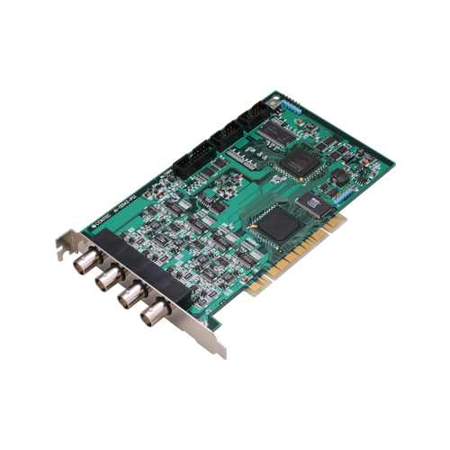
AI-1204Z-PCI
PCI AD card 10MS/s 12 Bit 4 CH BNC + 4*DI + 4*DO
1180,00 EUR
including VAT 1,404.20 EUR
- High‑Speed Sampling:
Maximum conversion rate of 10 MSPS (100 ns) with simultaneous sampling across all four analog input channels.
- Flexible Input Ranges:
Software‑selectable bipolar and unipolar ranges per channel:
±1.25 V / ±2.5 V / ±5 V / ±10 V or 0–2.5 V / 0–5 V / 0–10 V.
Each channel’s range can be independently configured.
- Large On‑Board Buffer:
32 M‑sample data buffer with bus‑master DMA transfer, enabling continuous high‑speed data acquisition without CPU load.
- Digital I/O Capability:
Four LVTTL‑level digital inputs and four LVTTL‑level digital outputs (non‑isolated).
Optional DT‑E3 cable provides access to digital I/O and control signals.
- Trigger and Control Flexibility:
Sampling can be started/stopped by software, external triggers, event controller outputs, or conversion data comparison (level/in‑range/out‑of‑range).
- Synchronization Support:
Built‑in synchronization control connectors (CN3/CN4) allow up to 16 boards to operate in synchronized mode, expanding total channel count.
- BNC Analog Connectors:
Four 50 Ω BNC connectors for direct connection to signal sources; optional 50 Ω termination resistors minimize reflection distortion.
- Software Calibration:
Full software‑based calibration for analog inputs; user calibration data can be stored in addition to factory calibration.
- Digital Filter:
Integrated digital filter prevents false triggering due to input signal chattering.
- Windows Driver Library:
Includes API‑PAC(W32) and API‑AIO(WDM) driver libraries for Windows 2000/XP/Vista/7/Server 2003, with sample programs for Visual Basic, Visual C++, Visual C#, Delphi, and C++ Builder.
- Synchronization Cable Included:
10 cm synchronization control cable supplied for multi‑board operation.
Maximum conversion rate of 10 MSPS (100 ns) with simultaneous sampling across all four analog input channels.
- Flexible Input Ranges:
Software‑selectable bipolar and unipolar ranges per channel:
±1.25 V / ±2.5 V / ±5 V / ±10 V or 0–2.5 V / 0–5 V / 0–10 V.
Each channel’s range can be independently configured.
- Large On‑Board Buffer:
32 M‑sample data buffer with bus‑master DMA transfer, enabling continuous high‑speed data acquisition without CPU load.
- Digital I/O Capability:
Four LVTTL‑level digital inputs and four LVTTL‑level digital outputs (non‑isolated).
Optional DT‑E3 cable provides access to digital I/O and control signals.
- Trigger and Control Flexibility:
Sampling can be started/stopped by software, external triggers, event controller outputs, or conversion data comparison (level/in‑range/out‑of‑range).
- Synchronization Support:
Built‑in synchronization control connectors (CN3/CN4) allow up to 16 boards to operate in synchronized mode, expanding total channel count.
- BNC Analog Connectors:
Four 50 Ω BNC connectors for direct connection to signal sources; optional 50 Ω termination resistors minimize reflection distortion.
- Software Calibration:
Full software‑based calibration for analog inputs; user calibration data can be stored in addition to factory calibration.
- Digital Filter:
Integrated digital filter prevents false triggering due to input signal chattering.
- Windows Driver Library:
Includes API‑PAC(W32) and API‑AIO(WDM) driver libraries for Windows 2000/XP/Vista/7/Server 2003, with sample programs for Visual Basic, Visual C++, Visual C#, Delphi, and C++ Builder.
- Synchronization Cable Included:
10 cm synchronization control cable supplied for multi‑board operation.
Comprehensive Product Summary – AI‑1204Z‑PCI PCI Analog Input Board
### 1. Product Overview
Product Name: AI‑1204Z‑PCI
Model Number: AI‑1204Z‑PCI
Series: PCI Analog Input (AD) Board Series
Article Number: AI‑1204Z‑PCI
Manufacturer: CONTEC CO., LTD. (Japan)
Product Type: PCI Bus Analog Input (A/D) Interface Board
Version: Ver.1.04
The CONTEC AI‑1204Z‑PCI is a high‑speed, 12‑bit, 4‑channel analog input board designed for PCI bus systems. It provides simultaneous sampling at up to 10 MS/s per channel, with flexible input ranges, digital I/O capability, and synchronization support for multi‑board configurations. The board is intended for high‑performance data acquisition, measurement, and control applications requiring precise analog signal capture and digital interfacing.
### 2. Key Features
- High‑Speed Sampling:
Maximum conversion rate of 10 MSPS (100 ns) with simultaneous sampling across all four analog input channels.
- Flexible Input Ranges:
Software‑selectable bipolar and unipolar ranges per channel:
±1.25 V / ±2.5 V / ±5 V / ±10 V or 0–2.5 V / 0–5 V / 0–10 V.
Each channel’s range can be independently configured.
- Large On‑Board Buffer:
32 M‑sample data buffer with bus‑master DMA transfer, enabling continuous high‑speed data acquisition without CPU load.
- Digital I/O Capability:
Four LVTTL‑level digital inputs and four LVTTL‑level digital outputs (non‑isolated).
Optional DT‑E3 cable provides access to digital I/O and control signals.
- Trigger and Control Flexibility:
Sampling can be started/stopped by software, external triggers, event controller outputs, or conversion data comparison (level/in‑range/out‑of‑range).
- Synchronization Support:
Built‑in synchronization control connectors (CN3/CN4) allow up to 16 boards to operate in synchronized mode, expanding total channel count.
- BNC Analog Connectors:
Four 50 Ω BNC connectors for direct connection to signal sources; optional 50 Ω termination resistors minimize reflection distortion.
- Software Calibration:
Full software‑based calibration for analog inputs; user calibration data can be stored in addition to factory calibration.
- Digital Filter:
Integrated digital filter prevents false triggering due to input signal chattering.
- Windows Driver Library:
Includes API‑PAC(W32) and API‑AIO(WDM) driver libraries for Windows 2000/XP/Vista/7/Server 2003, with sample programs for Visual Basic, Visual C++, Visual C#, Delphi, and C++ Builder.
- Synchronization Cable Included:
10 cm synchronization control cable supplied for multi‑board operation.
### 3. Technical Specifications
Analog Input Section
- Type: Single‑ended, non‑isolated
- Channels: 4
- Resolution: 12 bits (4096 levels)
- Conversion Speed: 100 ns (10 MSPS max)
- Input Ranges:
- Bipolar: ±10 V, ±5 V, ±2.5 V, ±1.25 V
- Unipolar: 0–10 V, 0–5 V, 0–2.5 V
- With 50 Ω termination enabled: ±5 V, ±2.5 V, ±1.25 V or 0–5 V, 0–2.5 V
- Input Impedance: ≥ 1 MΩ (normal), 50 Ω ± 1 % (terminated)
- Absolute Max Input Voltage:
- Power ON: ±13 V (no termination) / ±7 V (terminated)
- Power OFF: ±13 V (no termination) / ±7 V (terminated)
- Conversion Accuracy:
- ±4 LSB (±10 V range)
- ±6 LSB (0–10 V, ±5 V)
- ±8 LSB (0–5 V, ±2.5 V)
- ±10 LSB (0–2.5 V, ±1.25 V)
- Non‑Linearity Error: ±3 LSB (approx. 0.1 % over full range at 0–50 °C)
- Passband (–3 dB): 10 MHz
- Buffer Memory: 32 M samples
- Termination: Software‑selectable 50 Ω per channel
- Connectors: 4 × BNC (DB‑414K equivalent, 50 Ω characteristic impedance)
Digital I/O Section
- Inputs: 4 channels, LVTTL positive logic
- Outputs: 4 channels, LVTTL positive logic
- Digital Filter: Configurable (50 ns / 1 µs / 10 µs / 100 µs)
- Connector: 16‑pin pin‑header (CN2)
- Optional Cable: DT‑E3 (16‑pin → 15‑pin D‑SUB)
Trigger and Clock Signals
- External Start/Stop/Clock: LVTTL level, rising/falling edge selectable
- External Status Output: LVTTL sampling clock output
- Conversion Start Triggers: Software, data comparison, external trigger, event controller output
- Conversion Stop Triggers: Data save complete, data comparison, external trigger, event controller output, software command
Bus Master / DMA Section
- DMA Channels: 1
- Transfer Bus Width: 32 bit
- Max Transfer Length: 8 PCI data words
- FIFO: 1 K samples
- Scatter/Gather Function: 64 MB
Synchronization Bus Section
- Control Output/Input: Software‑selectable master/slave configuration
- Max Boards in Sync: 16 (including master)
- Connectors: CN3, CN4 (PS‑10PE‑D4T1‑B1 × 2, JAE equivalent)
General / Electrical
- Bus Interface: PCI 32‑bit, 33 MHz, Universal key (supports 3.3 V and 5 V slots)
- Power Consumption: +5 V DC ± 5 %, 2.5 A (max)
- Operating Temperature: 0 – 50 °C
- Operating Humidity: 10 – 90 % RH (non‑condensing)
- Dimensions: 176.41 (L) × 105.68 (H) mm
- Weight: Approx. 150 g
### 4. Functionality
Operation Principle:
The AI‑1204Z‑PCI converts analog voltage signals into 12‑bit digital data using four simultaneous‑sampling A/D converters. Each channel’s range and termination can be configured independently via software. The board stores sampled data in its 32 M‑sample buffer and transfers it to the host PC through PCI bus‑master DMA, minimizing CPU overhead.
Use Cases & Applications:
- High‑speed data acquisition and waveform capture
- Industrial measurement and control systems
- Scientific instrumentation and laboratory automation
- Vibration, acoustic, or transient signal analysis
- Multi‑channel synchronized sampling systems
Compatibility:
- PCI 32‑bit 33 MHz slots (universal 3.3 V/5 V)
- Windows 2000/XP/Vista/7/Server 2003 (via API‑AIO(WDM))
- Programming languages: Visual Basic, C/C++, C#, Delphi, C++ Builder
Triggering & Control:
Sampling can be initiated or halted by software commands, external LVTTL triggers, or internal event controller outputs. Data comparison triggers allow acquisition based on signal thresholds or ranges. Independent start/stop conditions enable flexible control schemes.
Synchronization:
Multiple AI‑1204Z‑PCI boards can be linked via synchronization connectors (CN3/CN4) using the supplied cable. One board acts as master, distributing clock and trigger signals to up to 15 slave boards for fully synchronized multi‑channel operation.
### 5. Components & Accessories
Included Items:
- AI‑1204Z‑PCI board × 1
- Synchronization control cable (10 cm) × 1
- CD‑ROM (API‑PAC(W32) driver library and User’s Guide) × 1
- First Step Guide × 1
Optional Cables (Analog I/O):
- BNC‑B100 (1 m)
- BNC‑B200 (2 m)
- BNC‑B300 (3 m)
Optional Cables (Digital I/O):
- DT‑E3 (16‑pin → 15‑pin D‑SUB with bracket, 150 mm)
- DT/E1 (flat cable 1.5 m, 16‑pin header)
- PCA15P‑1.5 (1.5 m, 15‑pin D‑SUB one end)
- PCB15P‑1.5 (1.5 m, 15‑pin D‑SUB both ends)
- PCB15PS‑0.5P (0.5 m shielded 15‑pin D‑SUB both ends)
- PCB15PS‑1.5P (1.5 m shielded 15‑pin D‑SUB both ends)
Optional Accessories:
- FTP‑15 (General Purpose Terminal block, M3 × 15 P) – requires DT‑E3 and PCB15P‑1.5
### 6. Installation & Setup
Hardware Installation Steps:
1. Power off the PC and remove the cover.
2. Insert the AI‑1204Z‑PCI into an available PCI slot (supports 3.3 V and 5 V keyed slots).
3. Secure the bracket with a screw.
4. Connect analog and digital cables as required.
5. Power on the PC; Windows will detect the new hardware.
6. Install the driver from the supplied CD‑ROM or download the latest version from CONTEC’s website.
Switch Settings:
- Board ID (SW5): Rotary switch 0–F for multi‑board identification (0 = default).
- Termination Resistors (SW1–SW4): Enable 50 Ω termination per channel (OFF by default).
Software Setup:
- Install API‑PAC(W32) before inserting the board.
- Configure device name via Windows Device Manager.
- Use the Diagnosis Program to verify operation.
Calibration:
Software‑based calibration utility accessible from the device property page. Requires a precision voltage source (≥ 4 decimal places). Factory calibration data can be restored if needed.
### 7. Performance & Capabilities
- Sampling Rate: 10 MS/s max (100 ns conversion time)
- Simultaneous Channels: 4
- Buffer Capacity: 32 M samples (continuous acquisition supported)
- Passband: 10 MHz (–3 dB)
- DMA Transfer: 32‑bit bus master mode with scatter/gather support (64 MB max)
- Synchronization: Up to 16 boards linked (master + 15 slaves)
- Digital I/O Speed: LVTTL logic compatible (typical 50 ns response)
- Accuracy: ±4 to ±10 LSB depending on range
- Non‑Linearity: ±3 LSB (typ.)
- Temperature Drift: Approx. 0.1 % over 0–50 °C
- Limitations: No galvanic isolation; input voltage must not exceed ±13 V (no termination) or ±7 V (terminated).
### 8. Standards & Compliance
- Bus Specification: PCI Rev. 2.2 (32‑bit, 33 MHz, Universal Key)
- Electrical Safety: Requires +5 V supply from PCI slot (does not operate on +3.3 V only)
- Environmental: 0–50 °C operating, 10–90 % RH non‑condensing
- EMC Compliance: Meets CE EMC Directive when used with shielded cables
- RoHS Compliance: Conforms to RoHS directives for hazardous substance control
- Quality Assurance: Factory calibrated and tested per CONTEC standards
### 9. Additional Information
Warranty:
Limited three‑year warranty covering defects in materials and workmanship. Excludes damage from misuse, modification, or improper installation.
Support & Service:
- Technical documentation, updated drivers, and sample code available at [https://www.contec.com](https://www.contec.com).
- Return Merchandise Authorization (RMA) required for repairs or replacement.
Maintenance:
- Periodic inspection recommended to ensure clean connectors and secure seating.
- Avoid static discharge and mechanical shock.
- Store in anti‑static packaging when not in use.
Software Tools:
- API‑AIO(WDM): Windows driver library (DLL) with Win32 API functions.
- Sample Programs: Analog input/output, triggered acquisition, multi‑device synchronization, digital I/O control.
- Diagnostic Utility: Verifies hardware operation and generates diagnostic reports.
- Calibration Utility: Performs software calibration and restores factory settings.
Safety Precautions:
- Do not connect outputs to ground or each other.
- Avoid touching BNC connectors while powered.
- Ensure adequate PC power supply (+5 V 2.5 A min).
- Use shielded cables for EMC compliance.
### Summary
The CONTEC AI‑1204Z‑PCI is a robust, high‑speed PCI analog input board engineered for precision data acquisition and control. With 10 MS/s 12‑bit simultaneous sampling, 32 M‑sample buffer, LVTTL digital I/O, and multi‑board synchronization, it delivers exceptional performance for laboratory, industrial, and embedded measurement systems. Its software‑configurable ranges, digital filtering, and software calibration simplify integration and ensure reliable, accurate results. Comprehensive Windows driver support and sample code make it ideal for developers building custom measurement and automation solutions.
### 1. Product Overview
Product Name: AI‑1204Z‑PCI
Model Number: AI‑1204Z‑PCI
Series: PCI Analog Input (AD) Board Series
Article Number: AI‑1204Z‑PCI
Manufacturer: CONTEC CO., LTD. (Japan)
Product Type: PCI Bus Analog Input (A/D) Interface Board
Version: Ver.1.04
The CONTEC AI‑1204Z‑PCI is a high‑speed, 12‑bit, 4‑channel analog input board designed for PCI bus systems. It provides simultaneous sampling at up to 10 MS/s per channel, with flexible input ranges, digital I/O capability, and synchronization support for multi‑board configurations. The board is intended for high‑performance data acquisition, measurement, and control applications requiring precise analog signal capture and digital interfacing.
### 2. Key Features
- High‑Speed Sampling:
Maximum conversion rate of 10 MSPS (100 ns) with simultaneous sampling across all four analog input channels.
- Flexible Input Ranges:
Software‑selectable bipolar and unipolar ranges per channel:
±1.25 V / ±2.5 V / ±5 V / ±10 V or 0–2.5 V / 0–5 V / 0–10 V.
Each channel’s range can be independently configured.
- Large On‑Board Buffer:
32 M‑sample data buffer with bus‑master DMA transfer, enabling continuous high‑speed data acquisition without CPU load.
- Digital I/O Capability:
Four LVTTL‑level digital inputs and four LVTTL‑level digital outputs (non‑isolated).
Optional DT‑E3 cable provides access to digital I/O and control signals.
- Trigger and Control Flexibility:
Sampling can be started/stopped by software, external triggers, event controller outputs, or conversion data comparison (level/in‑range/out‑of‑range).
- Synchronization Support:
Built‑in synchronization control connectors (CN3/CN4) allow up to 16 boards to operate in synchronized mode, expanding total channel count.
- BNC Analog Connectors:
Four 50 Ω BNC connectors for direct connection to signal sources; optional 50 Ω termination resistors minimize reflection distortion.
- Software Calibration:
Full software‑based calibration for analog inputs; user calibration data can be stored in addition to factory calibration.
- Digital Filter:
Integrated digital filter prevents false triggering due to input signal chattering.
- Windows Driver Library:
Includes API‑PAC(W32) and API‑AIO(WDM) driver libraries for Windows 2000/XP/Vista/7/Server 2003, with sample programs for Visual Basic, Visual C++, Visual C#, Delphi, and C++ Builder.
- Synchronization Cable Included:
10 cm synchronization control cable supplied for multi‑board operation.
### 3. Technical Specifications
Analog Input Section
- Type: Single‑ended, non‑isolated
- Channels: 4
- Resolution: 12 bits (4096 levels)
- Conversion Speed: 100 ns (10 MSPS max)
- Input Ranges:
- Bipolar: ±10 V, ±5 V, ±2.5 V, ±1.25 V
- Unipolar: 0–10 V, 0–5 V, 0–2.5 V
- With 50 Ω termination enabled: ±5 V, ±2.5 V, ±1.25 V or 0–5 V, 0–2.5 V
- Input Impedance: ≥ 1 MΩ (normal), 50 Ω ± 1 % (terminated)
- Absolute Max Input Voltage:
- Power ON: ±13 V (no termination) / ±7 V (terminated)
- Power OFF: ±13 V (no termination) / ±7 V (terminated)
- Conversion Accuracy:
- ±4 LSB (±10 V range)
- ±6 LSB (0–10 V, ±5 V)
- ±8 LSB (0–5 V, ±2.5 V)
- ±10 LSB (0–2.5 V, ±1.25 V)
- Non‑Linearity Error: ±3 LSB (approx. 0.1 % over full range at 0–50 °C)
- Passband (–3 dB): 10 MHz
- Buffer Memory: 32 M samples
- Termination: Software‑selectable 50 Ω per channel
- Connectors: 4 × BNC (DB‑414K equivalent, 50 Ω characteristic impedance)
Digital I/O Section
- Inputs: 4 channels, LVTTL positive logic
- Outputs: 4 channels, LVTTL positive logic
- Digital Filter: Configurable (50 ns / 1 µs / 10 µs / 100 µs)
- Connector: 16‑pin pin‑header (CN2)
- Optional Cable: DT‑E3 (16‑pin → 15‑pin D‑SUB)
Trigger and Clock Signals
- External Start/Stop/Clock: LVTTL level, rising/falling edge selectable
- External Status Output: LVTTL sampling clock output
- Conversion Start Triggers: Software, data comparison, external trigger, event controller output
- Conversion Stop Triggers: Data save complete, data comparison, external trigger, event controller output, software command
Bus Master / DMA Section
- DMA Channels: 1
- Transfer Bus Width: 32 bit
- Max Transfer Length: 8 PCI data words
- FIFO: 1 K samples
- Scatter/Gather Function: 64 MB
Synchronization Bus Section
- Control Output/Input: Software‑selectable master/slave configuration
- Max Boards in Sync: 16 (including master)
- Connectors: CN3, CN4 (PS‑10PE‑D4T1‑B1 × 2, JAE equivalent)
General / Electrical
- Bus Interface: PCI 32‑bit, 33 MHz, Universal key (supports 3.3 V and 5 V slots)
- Power Consumption: +5 V DC ± 5 %, 2.5 A (max)
- Operating Temperature: 0 – 50 °C
- Operating Humidity: 10 – 90 % RH (non‑condensing)
- Dimensions: 176.41 (L) × 105.68 (H) mm
- Weight: Approx. 150 g
### 4. Functionality
Operation Principle:
The AI‑1204Z‑PCI converts analog voltage signals into 12‑bit digital data using four simultaneous‑sampling A/D converters. Each channel’s range and termination can be configured independently via software. The board stores sampled data in its 32 M‑sample buffer and transfers it to the host PC through PCI bus‑master DMA, minimizing CPU overhead.
Use Cases & Applications:
- High‑speed data acquisition and waveform capture
- Industrial measurement and control systems
- Scientific instrumentation and laboratory automation
- Vibration, acoustic, or transient signal analysis
- Multi‑channel synchronized sampling systems
Compatibility:
- PCI 32‑bit 33 MHz slots (universal 3.3 V/5 V)
- Windows 2000/XP/Vista/7/Server 2003 (via API‑AIO(WDM))
- Programming languages: Visual Basic, C/C++, C#, Delphi, C++ Builder
Triggering & Control:
Sampling can be initiated or halted by software commands, external LVTTL triggers, or internal event controller outputs. Data comparison triggers allow acquisition based on signal thresholds or ranges. Independent start/stop conditions enable flexible control schemes.
Synchronization:
Multiple AI‑1204Z‑PCI boards can be linked via synchronization connectors (CN3/CN4) using the supplied cable. One board acts as master, distributing clock and trigger signals to up to 15 slave boards for fully synchronized multi‑channel operation.
### 5. Components & Accessories
Included Items:
- AI‑1204Z‑PCI board × 1
- Synchronization control cable (10 cm) × 1
- CD‑ROM (API‑PAC(W32) driver library and User’s Guide) × 1
- First Step Guide × 1
Optional Cables (Analog I/O):
- BNC‑B100 (1 m)
- BNC‑B200 (2 m)
- BNC‑B300 (3 m)
Optional Cables (Digital I/O):
- DT‑E3 (16‑pin → 15‑pin D‑SUB with bracket, 150 mm)
- DT/E1 (flat cable 1.5 m, 16‑pin header)
- PCA15P‑1.5 (1.5 m, 15‑pin D‑SUB one end)
- PCB15P‑1.5 (1.5 m, 15‑pin D‑SUB both ends)
- PCB15PS‑0.5P (0.5 m shielded 15‑pin D‑SUB both ends)
- PCB15PS‑1.5P (1.5 m shielded 15‑pin D‑SUB both ends)
Optional Accessories:
- FTP‑15 (General Purpose Terminal block, M3 × 15 P) – requires DT‑E3 and PCB15P‑1.5
### 6. Installation & Setup
Hardware Installation Steps:
1. Power off the PC and remove the cover.
2. Insert the AI‑1204Z‑PCI into an available PCI slot (supports 3.3 V and 5 V keyed slots).
3. Secure the bracket with a screw.
4. Connect analog and digital cables as required.
5. Power on the PC; Windows will detect the new hardware.
6. Install the driver from the supplied CD‑ROM or download the latest version from CONTEC’s website.
Switch Settings:
- Board ID (SW5): Rotary switch 0–F for multi‑board identification (0 = default).
- Termination Resistors (SW1–SW4): Enable 50 Ω termination per channel (OFF by default).
Software Setup:
- Install API‑PAC(W32) before inserting the board.
- Configure device name via Windows Device Manager.
- Use the Diagnosis Program to verify operation.
Calibration:
Software‑based calibration utility accessible from the device property page. Requires a precision voltage source (≥ 4 decimal places). Factory calibration data can be restored if needed.
### 7. Performance & Capabilities
- Sampling Rate: 10 MS/s max (100 ns conversion time)
- Simultaneous Channels: 4
- Buffer Capacity: 32 M samples (continuous acquisition supported)
- Passband: 10 MHz (–3 dB)
- DMA Transfer: 32‑bit bus master mode with scatter/gather support (64 MB max)
- Synchronization: Up to 16 boards linked (master + 15 slaves)
- Digital I/O Speed: LVTTL logic compatible (typical 50 ns response)
- Accuracy: ±4 to ±10 LSB depending on range
- Non‑Linearity: ±3 LSB (typ.)
- Temperature Drift: Approx. 0.1 % over 0–50 °C
- Limitations: No galvanic isolation; input voltage must not exceed ±13 V (no termination) or ±7 V (terminated).
### 8. Standards & Compliance
- Bus Specification: PCI Rev. 2.2 (32‑bit, 33 MHz, Universal Key)
- Electrical Safety: Requires +5 V supply from PCI slot (does not operate on +3.3 V only)
- Environmental: 0–50 °C operating, 10–90 % RH non‑condensing
- EMC Compliance: Meets CE EMC Directive when used with shielded cables
- RoHS Compliance: Conforms to RoHS directives for hazardous substance control
- Quality Assurance: Factory calibrated and tested per CONTEC standards
### 9. Additional Information
Warranty:
Limited three‑year warranty covering defects in materials and workmanship. Excludes damage from misuse, modification, or improper installation.
Support & Service:
- Technical documentation, updated drivers, and sample code available at [https://www.contec.com](https://www.contec.com).
- Return Merchandise Authorization (RMA) required for repairs or replacement.
Maintenance:
- Periodic inspection recommended to ensure clean connectors and secure seating.
- Avoid static discharge and mechanical shock.
- Store in anti‑static packaging when not in use.
Software Tools:
- API‑AIO(WDM): Windows driver library (DLL) with Win32 API functions.
- Sample Programs: Analog input/output, triggered acquisition, multi‑device synchronization, digital I/O control.
- Diagnostic Utility: Verifies hardware operation and generates diagnostic reports.
- Calibration Utility: Performs software calibration and restores factory settings.
Safety Precautions:
- Do not connect outputs to ground or each other.
- Avoid touching BNC connectors while powered.
- Ensure adequate PC power supply (+5 V 2.5 A min).
- Use shielded cables for EMC compliance.
### Summary
The CONTEC AI‑1204Z‑PCI is a robust, high‑speed PCI analog input board engineered for precision data acquisition and control. With 10 MS/s 12‑bit simultaneous sampling, 32 M‑sample buffer, LVTTL digital I/O, and multi‑board synchronization, it delivers exceptional performance for laboratory, industrial, and embedded measurement systems. Its software‑configurable ranges, digital filtering, and software calibration simplify integration and ensure reliable, accurate results. Comprehensive Windows driver support and sample code make it ideal for developers building custom measurement and automation solutions.
-
 ds_ai1204zpci_en.pdf
PDF Catalog
ds_ai1204zpci_en.pdf
PDF Catalog
-
 man_AI-1204Z-PCI.pdf
Manual
man_AI-1204Z-PCI.pdf
Manual
No accessories available.

ev_up_rgb_96dpi_500x500.jpg)