
 LOOKING FOR THE RIGHT
INDUSTRIAL SOLUTION?
Discover embedded, communication and automation solutions tailored to your application.
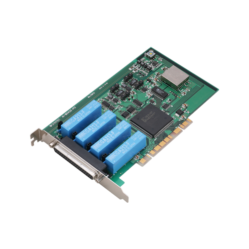
AI-1604CI2-PCI
PCI card isolated AD 50kS/s 16 Bit 4 CH + Timer + Trigger In
1190,00 EUR
including VAT 1,416.10 EUR
- Four 16‑bit Analog Input Channels:
Each channel supports independent configuration for voltage or current input, with software‑selectable ranges.
- High Sampling Rate:
Maximum conversion speed of 20 µs per channel (50 kS/s).
- Individual Channel Isolation:
500 Vrms isolation between channels and between the board and the PC bus, allowing safe measurement of signals with different ground potentials.
- Flexible Input Ranges:
Bipolar ±10 V, ±5 V and unipolar 0–10 V, 0–5 V voltage ranges, or 4–20 mA current input. Voltage/current mode is jumper‑selectable per channel; range is software‑selectable.
- Programmable Timer:
Built‑in high‑precision timer configurable in 250 ns increments, supporting timing intervals from 500 ns to 1,073,741,824,000 ns.
- External Trigger and Sampling Clock:
Optocoupler‑isolated inputs for external trigger and sampling clock signals, compatible with current‑sink outputs.
- Software‑Controlled Sampling:
Sampling start/stop can be controlled by software, external triggers, or comparison of converted data.
- Driver and Software Support:
Includes Windows and Linux driver libraries (API‑PAC(W32)), diagnostic utilities, and LabVIEW support via the VI‑DAQ library.
- PCI Bus Compatibility:
32‑bit, 33 MHz PCI interface with universal keying for both 3.3 V and 5 V slots (requires +5 V power).
- Compact and Lightweight:
Board dimensions 176.41 mm (L) × 106.68 mm (H); weight approximately 200 g.
Each channel supports independent configuration for voltage or current input, with software‑selectable ranges.
- High Sampling Rate:
Maximum conversion speed of 20 µs per channel (50 kS/s).
- Individual Channel Isolation:
500 Vrms isolation between channels and between the board and the PC bus, allowing safe measurement of signals with different ground potentials.
- Flexible Input Ranges:
Bipolar ±10 V, ±5 V and unipolar 0–10 V, 0–5 V voltage ranges, or 4–20 mA current input. Voltage/current mode is jumper‑selectable per channel; range is software‑selectable.
- Programmable Timer:
Built‑in high‑precision timer configurable in 250 ns increments, supporting timing intervals from 500 ns to 1,073,741,824,000 ns.
- External Trigger and Sampling Clock:
Optocoupler‑isolated inputs for external trigger and sampling clock signals, compatible with current‑sink outputs.
- Software‑Controlled Sampling:
Sampling start/stop can be controlled by software, external triggers, or comparison of converted data.
- Driver and Software Support:
Includes Windows and Linux driver libraries (API‑PAC(W32)), diagnostic utilities, and LabVIEW support via the VI‑DAQ library.
- PCI Bus Compatibility:
32‑bit, 33 MHz PCI interface with universal keying for both 3.3 V and 5 V slots (requires +5 V power).
- Compact and Lightweight:
Board dimensions 176.41 mm (L) × 106.68 mm (H); weight approximately 200 g.
Comprehensive Product Summary – AI‑1604CI2‑PCI Isolated Analog Input Board
### 1. Product Overview
Product Name: AI‑1604CI2‑PCI
Model / Article Number: AI‑1604CI2‑PCI
Series: Isolated Analog Input Board for PCI
Manufacturer: CONTEC CO., LTD.
Version: Ver.1.02
Product Description:
The AI‑1604CI2‑PCI is a high‑precision, isolated analog input board designed for PCI bus systems. It provides four channels of 16‑bit analog input with individual channel isolation and bus isolation from the host PC. The board supports both voltage and current input modes, programmable voltage ranges, and features a built‑in high‑precision timer and optically isolated external trigger input. It is intended for data acquisition, measurement, and control applications requiring high accuracy and electrical isolation.
### 2. Key Features
- Four 16‑bit Analog Input Channels:
Each channel supports independent configuration for voltage or current input, with software‑selectable ranges.
- High Sampling Rate:
Maximum conversion speed of 20 µs per channel (50 kS/s).
- Individual Channel Isolation:
500 Vrms isolation between channels and between the board and the PC bus, allowing safe measurement of signals with different ground potentials.
- Flexible Input Ranges:
Bipolar ±10 V, ±5 V and unipolar 0–10 V, 0–5 V voltage ranges, or 4–20 mA current input. Voltage/current mode is jumper‑selectable per channel; range is software‑selectable.
- Programmable Timer:
Built‑in high‑precision timer configurable in 250 ns increments, supporting timing intervals from 500 ns to 1,073,741,824,000 ns.
- External Trigger and Sampling Clock:
Optocoupler‑isolated inputs for external trigger and sampling clock signals, compatible with current‑sink outputs.
- Software‑Controlled Sampling:
Sampling start/stop can be controlled by software, external triggers, or comparison of converted data.
- Driver and Software Support:
Includes Windows and Linux driver libraries (API‑PAC(W32)), diagnostic utilities, and LabVIEW support via the VI‑DAQ library.
- PCI Bus Compatibility:
32‑bit, 33 MHz PCI interface with universal keying for both 3.3 V and 5 V slots (requires +5 V power).
- Compact and Lightweight:
Board dimensions 176.41 mm (L) × 106.68 mm (H); weight approximately 200 g.
### 3. Technical Specifications
| Parameter | Specification |
|----------------|------------------|
| Analog Input Type | Single‑ended, channel‑isolated |
| Number of Channels | 4 |
| Resolution | 16 bit |
| Input Ranges | ±10 V, ±5 V, 0–10 V, 0–5 V, 4–20 mA |
| Absolute Maximum Input | ±11 V (voltage), 30 mA (current) |
| Input Impedance | ≥ 1 MΩ (power ON), ≥ 1 kΩ (power OFF) |
| Non‑linearity Error | ±32 LSB (±10 V), ±64 LSB (±5 V, 0–10 V, 0–5 V), ±80 LSB (4–20 mA) |
| Conversion Speed | 20 µs / ch (50 kS/s max) |
| Passband (–3 dB) | 1 kHz |
| Isolation Voltage | 500 Vrms between channels and bus |
| Sampling Clock | Internal (20,000–1,073,741,824,000 ns, 250 ns step) or external (optocoupler‑isolated) |
| Timer Setup Frequency | 500–1,073,741,824,000 ns (250 ns step) |
| Timer Output | Optocoupler‑isolated open collector (current sink type) |
| External Trigger Input | Optocoupler‑isolated, current‑sink compatible |
| I/O Address | 32‑port boundary |
| Interrupt Level | 1 level |
| Power Consumption | +5 V DC ±5%, 1100 mA max |
| Operating Temperature | 0 – 50 °C |
| Operating Humidity | 10 – 90 % RH (non‑condensing) |
| Bus Interface | PCI 32‑bit, 33 MHz, universal keying |
| Connector Type | 37‑pin D‑SUB female (JAE DCLC‑J37SAF‑20L9E or equivalent) |
| Dimensions | 176.41 mm (L) × 106.68 mm (H) |
| Weight | Approx. 200 g |
### 4. Functionality
Operating Principle:
The AI‑1604CI2‑PCI converts analog voltage or current signals into 16‑bit digital data through isolated amplifiers and an A/D converter. Each channel is electrically isolated, preventing ground loops and interference between channels or between the PC and external devices.
Use Cases and Applications:
- Industrial process monitoring and control
- Sensor signal acquisition (temperature, pressure, flow, etc.)
- Laboratory instrumentation and test automation
- Data logging and waveform capture
- Integration with LabVIEW or custom software for real‑time analysis
Compatibility:
- Operating Systems: Windows Vista/XP/2000/Server 2003, Linux (Red Hat, TurboLinux)
- Software Environments: Visual Basic, C/C++, C#, Delphi, C++ Builder, gcc
- LabVIEW Integration: Supported via VI‑DAQ library (free download)
Sampling Control:
Sampling can be initiated or stopped by software commands, external triggers, or data comparison thresholds. The sampling clock can be internal or externally supplied.
Isolation and Safety:
500 Vrms isolation ensures safe operation in environments with differing ground potentials or electrical noise.
### 5. Components & Accessories
Included Items:
- AI‑1604CI2‑PCI board × 1
- First Step Guide × 1
- Driver Library Disk (API‑PAC(W32)) × 1
- Serial Number Label × 1
- Product Registration Card & Warranty Certificate × 1
Optional Cables:
- PCA37P‑1.5 (1.5 m) – Flat cable, 37‑pin D‑SUB (female)
- PCA37PS‑0.5P (0.5 m) / PCA37PS‑1.5P (1.5 m) – Shielded cable, 37‑pin D‑SUB (female)
- PCB37P‑1.5 (1.5 m) – Flat cable, D‑SUB connectors both ends
- PCB37PS‑0.5P / PCB37PS‑1.5P – Shielded cable both ends
- CN5‑D37M – 37‑pin D‑SUB male connector set (5 pcs)
Optional Terminal Units:
- EPD‑37A (M3 × 37P, spring‑up type)
- EPD‑37 (M3.5 × 37P)
- DTP‑3A (M3 × 37P)
- DTP‑4A (M2.6 × 37P)
(*Requires PCB37P‑* or PCB37PS‑* cable; 0.5 m recommended.*)
### 6. Installation & Setup
Hardware Setup:
1. Set Board ID: Rotary switch (SW1) 0–Fh for up to 16 boards.
2. Configure Input Type: Jumpers JP1–JP4 select voltage or current input per channel.
3. Install Board: Insert into a PCI 32‑bit 33 MHz slot (supports 3.3 V and 5 V keying).
4. Power Requirement: +5 V DC from PCI slot; not compatible with +3.3 V‑only systems.
Software Installation:
- Install API‑PAC(W32) driver library before inserting the board.
- Supported drivers: API‑AIO(WDM) (for modern Windows) and API‑AIO(98/PC) (for legacy systems).
- Linux driver API‑AIO(LNX) available on CD‑ROM.
- LabVIEW VI‑DAQ library downloadable from [www.contec.com/vidaq](http://www.contec.com/vidaq/).
Configuration:
- Device recognized as “ADI16‑4C(PCI)” in Windows Device Manager.
- Use API‑TOOL Configuration utility to assign device names and verify operation.
- Diagnostic program included for hardware verification.
Connection Guidelines:
- Use short, shielded cables for noise immunity.
- Connect unused analog inputs to analog ground.
- Do not exceed ±11 V or 30 mA input limits.
- External control signals require 12–24 V DC power supply.
### 7. Performance & Capabilities
Analog Input Performance:
- 16‑bit resolution provides 65,536 discrete levels.
- Maximum throughput: 50 kS/s per channel.
- Passband: 1 kHz (–3 dB).
- Typical non‑linearity: ±32 LSB (±10 V range).
- Input impedance ≥ 1 MΩ ensures minimal loading.
Timer and Trigger Performance:
- Programmable timer resolution: 250 ns.
- External trigger delay: ≤ 5 µs.
- External sampling clock setup/hold: ≥ 2.5 µs.
- Timer output pulse width: ≈ 3 µs (typical at 24 V load 510 Ω).
Electrical Isolation:
- 500 Vrms isolation between channels and system ground.
- Optocoupler isolation for all external control lines.
Limitations:
- No onboard buffer memory (data stored via driver).
- Requires +5 V PCI power; not operable in +3.3 V‑only slots.
- Passband limited to 1 kHz for high‑accuracy isolation amplifiers.
### 8. Standards & Compliance
- Bus Interface: PCI 2.2 compliant (32‑bit, 33 MHz).
- Isolation: 500 Vrms channel‑to‑channel and channel‑to‑bus.
- Environmental: 0–50 °C operating, 10–90 % RH non‑condensing.
- RoHS Compliance: Lead‑free, environmentally friendly design.
- Safety: Optocoupler isolation for external I/O; surge protection recommended for inductive loads.
- EMC: Designed for industrial environments with noise immunity through isolation and shielding.
### 9. Additional Information
Warranty:
Limited three‑year warranty covering defects in materials and workmanship. Excludes damage from misuse, modification, or improper installation. RMA required for service.
Support & Resources:
- Websites:
- Japanese: [http://www.contec.co.jp/](http://www.contec.co.jp/)
- English: [http://www.contec.com/](http://www.contec.com/)
- Chinese: [http://www.contec.com.cn/](http://www.contec.com.cn/)
- Downloads: Updated drivers, sample programs, and documentation available online.
- Technical Assistance: Diagnostic utilities and sample code for Visual Basic, C/C++, C#, Delphi, and LabVIEW.
Maintenance:
- Periodically inspect connectors and terminals for dust or corrosion.
- Store in anti‑static packaging when not in use.
- Avoid exposure to moisture, vibration, or corrosive gases.
Calibration:
Factory‑calibrated prior to shipment. Contact CONTEC for recalibration if performance deviates from specifications.
Product Evolution:
Successor to ADI16‑4C(PCI) and ADI16‑4C(PCI)‑N models with improved linearity and RoHS compliance. Backward‑compatible with previous software and hardware configurations.
### Summary
The CONTEC AI‑1604CI2‑PCI is a robust, high‑precision isolated analog input board for PCI systems, offering four individually isolated 16‑bit channels with flexible voltage and current input ranges. Its 50 kS/s sampling rate, 500 Vrms isolation, and optically isolated trigger/timer interfaces make it ideal for industrial measurement, control, and data acquisition applications. With comprehensive driver support for Windows, Linux, and LabVIEW, it integrates seamlessly into diverse development environments. The board’s design emphasizes electrical safety, accuracy, and reliability, backed by a three‑year warranty and extensive software ecosystem.
### 1. Product Overview
Product Name: AI‑1604CI2‑PCI
Model / Article Number: AI‑1604CI2‑PCI
Series: Isolated Analog Input Board for PCI
Manufacturer: CONTEC CO., LTD.
Version: Ver.1.02
Product Description:
The AI‑1604CI2‑PCI is a high‑precision, isolated analog input board designed for PCI bus systems. It provides four channels of 16‑bit analog input with individual channel isolation and bus isolation from the host PC. The board supports both voltage and current input modes, programmable voltage ranges, and features a built‑in high‑precision timer and optically isolated external trigger input. It is intended for data acquisition, measurement, and control applications requiring high accuracy and electrical isolation.
### 2. Key Features
- Four 16‑bit Analog Input Channels:
Each channel supports independent configuration for voltage or current input, with software‑selectable ranges.
- High Sampling Rate:
Maximum conversion speed of 20 µs per channel (50 kS/s).
- Individual Channel Isolation:
500 Vrms isolation between channels and between the board and the PC bus, allowing safe measurement of signals with different ground potentials.
- Flexible Input Ranges:
Bipolar ±10 V, ±5 V and unipolar 0–10 V, 0–5 V voltage ranges, or 4–20 mA current input. Voltage/current mode is jumper‑selectable per channel; range is software‑selectable.
- Programmable Timer:
Built‑in high‑precision timer configurable in 250 ns increments, supporting timing intervals from 500 ns to 1,073,741,824,000 ns.
- External Trigger and Sampling Clock:
Optocoupler‑isolated inputs for external trigger and sampling clock signals, compatible with current‑sink outputs.
- Software‑Controlled Sampling:
Sampling start/stop can be controlled by software, external triggers, or comparison of converted data.
- Driver and Software Support:
Includes Windows and Linux driver libraries (API‑PAC(W32)), diagnostic utilities, and LabVIEW support via the VI‑DAQ library.
- PCI Bus Compatibility:
32‑bit, 33 MHz PCI interface with universal keying for both 3.3 V and 5 V slots (requires +5 V power).
- Compact and Lightweight:
Board dimensions 176.41 mm (L) × 106.68 mm (H); weight approximately 200 g.
### 3. Technical Specifications
| Parameter | Specification |
|----------------|------------------|
| Analog Input Type | Single‑ended, channel‑isolated |
| Number of Channels | 4 |
| Resolution | 16 bit |
| Input Ranges | ±10 V, ±5 V, 0–10 V, 0–5 V, 4–20 mA |
| Absolute Maximum Input | ±11 V (voltage), 30 mA (current) |
| Input Impedance | ≥ 1 MΩ (power ON), ≥ 1 kΩ (power OFF) |
| Non‑linearity Error | ±32 LSB (±10 V), ±64 LSB (±5 V, 0–10 V, 0–5 V), ±80 LSB (4–20 mA) |
| Conversion Speed | 20 µs / ch (50 kS/s max) |
| Passband (–3 dB) | 1 kHz |
| Isolation Voltage | 500 Vrms between channels and bus |
| Sampling Clock | Internal (20,000–1,073,741,824,000 ns, 250 ns step) or external (optocoupler‑isolated) |
| Timer Setup Frequency | 500–1,073,741,824,000 ns (250 ns step) |
| Timer Output | Optocoupler‑isolated open collector (current sink type) |
| External Trigger Input | Optocoupler‑isolated, current‑sink compatible |
| I/O Address | 32‑port boundary |
| Interrupt Level | 1 level |
| Power Consumption | +5 V DC ±5%, 1100 mA max |
| Operating Temperature | 0 – 50 °C |
| Operating Humidity | 10 – 90 % RH (non‑condensing) |
| Bus Interface | PCI 32‑bit, 33 MHz, universal keying |
| Connector Type | 37‑pin D‑SUB female (JAE DCLC‑J37SAF‑20L9E or equivalent) |
| Dimensions | 176.41 mm (L) × 106.68 mm (H) |
| Weight | Approx. 200 g |
### 4. Functionality
Operating Principle:
The AI‑1604CI2‑PCI converts analog voltage or current signals into 16‑bit digital data through isolated amplifiers and an A/D converter. Each channel is electrically isolated, preventing ground loops and interference between channels or between the PC and external devices.
Use Cases and Applications:
- Industrial process monitoring and control
- Sensor signal acquisition (temperature, pressure, flow, etc.)
- Laboratory instrumentation and test automation
- Data logging and waveform capture
- Integration with LabVIEW or custom software for real‑time analysis
Compatibility:
- Operating Systems: Windows Vista/XP/2000/Server 2003, Linux (Red Hat, TurboLinux)
- Software Environments: Visual Basic, C/C++, C#, Delphi, C++ Builder, gcc
- LabVIEW Integration: Supported via VI‑DAQ library (free download)
Sampling Control:
Sampling can be initiated or stopped by software commands, external triggers, or data comparison thresholds. The sampling clock can be internal or externally supplied.
Isolation and Safety:
500 Vrms isolation ensures safe operation in environments with differing ground potentials or electrical noise.
### 5. Components & Accessories
Included Items:
- AI‑1604CI2‑PCI board × 1
- First Step Guide × 1
- Driver Library Disk (API‑PAC(W32)) × 1
- Serial Number Label × 1
- Product Registration Card & Warranty Certificate × 1
Optional Cables:
- PCA37P‑1.5 (1.5 m) – Flat cable, 37‑pin D‑SUB (female)
- PCA37PS‑0.5P (0.5 m) / PCA37PS‑1.5P (1.5 m) – Shielded cable, 37‑pin D‑SUB (female)
- PCB37P‑1.5 (1.5 m) – Flat cable, D‑SUB connectors both ends
- PCB37PS‑0.5P / PCB37PS‑1.5P – Shielded cable both ends
- CN5‑D37M – 37‑pin D‑SUB male connector set (5 pcs)
Optional Terminal Units:
- EPD‑37A (M3 × 37P, spring‑up type)
- EPD‑37 (M3.5 × 37P)
- DTP‑3A (M3 × 37P)
- DTP‑4A (M2.6 × 37P)
(*Requires PCB37P‑* or PCB37PS‑* cable; 0.5 m recommended.*)
### 6. Installation & Setup
Hardware Setup:
1. Set Board ID: Rotary switch (SW1) 0–Fh for up to 16 boards.
2. Configure Input Type: Jumpers JP1–JP4 select voltage or current input per channel.
3. Install Board: Insert into a PCI 32‑bit 33 MHz slot (supports 3.3 V and 5 V keying).
4. Power Requirement: +5 V DC from PCI slot; not compatible with +3.3 V‑only systems.
Software Installation:
- Install API‑PAC(W32) driver library before inserting the board.
- Supported drivers: API‑AIO(WDM) (for modern Windows) and API‑AIO(98/PC) (for legacy systems).
- Linux driver API‑AIO(LNX) available on CD‑ROM.
- LabVIEW VI‑DAQ library downloadable from [www.contec.com/vidaq](http://www.contec.com/vidaq/).
Configuration:
- Device recognized as “ADI16‑4C(PCI)” in Windows Device Manager.
- Use API‑TOOL Configuration utility to assign device names and verify operation.
- Diagnostic program included for hardware verification.
Connection Guidelines:
- Use short, shielded cables for noise immunity.
- Connect unused analog inputs to analog ground.
- Do not exceed ±11 V or 30 mA input limits.
- External control signals require 12–24 V DC power supply.
### 7. Performance & Capabilities
Analog Input Performance:
- 16‑bit resolution provides 65,536 discrete levels.
- Maximum throughput: 50 kS/s per channel.
- Passband: 1 kHz (–3 dB).
- Typical non‑linearity: ±32 LSB (±10 V range).
- Input impedance ≥ 1 MΩ ensures minimal loading.
Timer and Trigger Performance:
- Programmable timer resolution: 250 ns.
- External trigger delay: ≤ 5 µs.
- External sampling clock setup/hold: ≥ 2.5 µs.
- Timer output pulse width: ≈ 3 µs (typical at 24 V load 510 Ω).
Electrical Isolation:
- 500 Vrms isolation between channels and system ground.
- Optocoupler isolation for all external control lines.
Limitations:
- No onboard buffer memory (data stored via driver).
- Requires +5 V PCI power; not operable in +3.3 V‑only slots.
- Passband limited to 1 kHz for high‑accuracy isolation amplifiers.
### 8. Standards & Compliance
- Bus Interface: PCI 2.2 compliant (32‑bit, 33 MHz).
- Isolation: 500 Vrms channel‑to‑channel and channel‑to‑bus.
- Environmental: 0–50 °C operating, 10–90 % RH non‑condensing.
- RoHS Compliance: Lead‑free, environmentally friendly design.
- Safety: Optocoupler isolation for external I/O; surge protection recommended for inductive loads.
- EMC: Designed for industrial environments with noise immunity through isolation and shielding.
### 9. Additional Information
Warranty:
Limited three‑year warranty covering defects in materials and workmanship. Excludes damage from misuse, modification, or improper installation. RMA required for service.
Support & Resources:
- Websites:
- Japanese: [http://www.contec.co.jp/](http://www.contec.co.jp/)
- English: [http://www.contec.com/](http://www.contec.com/)
- Chinese: [http://www.contec.com.cn/](http://www.contec.com.cn/)
- Downloads: Updated drivers, sample programs, and documentation available online.
- Technical Assistance: Diagnostic utilities and sample code for Visual Basic, C/C++, C#, Delphi, and LabVIEW.
Maintenance:
- Periodically inspect connectors and terminals for dust or corrosion.
- Store in anti‑static packaging when not in use.
- Avoid exposure to moisture, vibration, or corrosive gases.
Calibration:
Factory‑calibrated prior to shipment. Contact CONTEC for recalibration if performance deviates from specifications.
Product Evolution:
Successor to ADI16‑4C(PCI) and ADI16‑4C(PCI)‑N models with improved linearity and RoHS compliance. Backward‑compatible with previous software and hardware configurations.
### Summary
The CONTEC AI‑1604CI2‑PCI is a robust, high‑precision isolated analog input board for PCI systems, offering four individually isolated 16‑bit channels with flexible voltage and current input ranges. Its 50 kS/s sampling rate, 500 Vrms isolation, and optically isolated trigger/timer interfaces make it ideal for industrial measurement, control, and data acquisition applications. With comprehensive driver support for Windows, Linux, and LabVIEW, it integrates seamlessly into diverse development environments. The board’s design emphasizes electrical safety, accuracy, and reliability, backed by a three‑year warranty and extensive software ecosystem.
-
 ds_ai1604ci2pci_en.pdf
PDF Catalog
ds_ai1604ci2pci_en.pdf
PDF Catalog
-
 man_AI-1604CI2-PCI.pdf
Manual
man_AI-1604CI2-PCI.pdf
Manual
No accessories available.
l_rgb_96dpi_500x500.jpg)
_rgb_96dpi_500x500.jpg)
l_conn_rgb_96dpi_500x500.jpg)