LOOKING FOR THE RIGHT
INDUSTRIAL SOLUTION?
Discover embedded, communication and automation solutions tailored to your application.

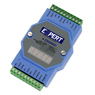
EX9065AHD-M
8*Photo-Mos Relay output, RS485, LED, Modbus, FW
207,00 EUR
including VAT 246.33 EUR
- 8‑Channel Photo‑MOS Relay Outputs:
Each output is a Form‑A (normally open) PhotoMOS relay providing electrical isolation and fast switching.
- Turn‑On Time: 0.7 ms
- Turn‑Off Time: 0.05 ms
- Output Resistance: 23 Ω
- I/O Capacitance: 0.8 pF (at 1 MHz)
- High Isolation and Safety:
- Channel‑to‑channel and channel‑to‑system isolation up to 5000 VAC.
- Protects control systems from surges, noise, and ground loops.
- Wide Output Range:
- Output Voltage: 0 – 350 VAC (peak)
- Output Current: 0 – 0.13 A (peak)
- RS‑485 Communication Interface:
- 2‑wire half‑duplex serial interface.
- Baud rates: 1200 – 115200 bps.
- Supports both Normal mode and Modbus RTU mode.
- Modbus RTU Protocol Support:
- Fully compatible with standard Modbus RTU master devices.
- Custom firmware ensures 3.5‑bit idle time between command and response for timing compliance.
- Supports Modbus function codes 0x01, 0x02, 0x03, 0x04, 0x05, 0x06, 0x0F, and watchdog‑related codes.
- Dual Watchdog System:
- Module Watchdog: Hardware circuit monitors internal operation and resets the module if a fault occurs.
- Host Watchdog: Software timer monitors communication with the host; if timeout occurs, outputs revert to safe values.
- LED Indicators:
- Per‑channel LED indicators for output status.
- Power and communication status LEDs for diagnostics.
- Wide Power Input Range:
- +10 V DC – +30 V DC input.
- Power consumption: 1.9 W typical.
- Rugged Industrial Design:
- Operating temperature: −25 °C – +75 °C.
- Compact DIN‑rail mountable housing.
- Designed for continuous operation in industrial control panels.
Each output is a Form‑A (normally open) PhotoMOS relay providing electrical isolation and fast switching.
- Turn‑On Time: 0.7 ms
- Turn‑Off Time: 0.05 ms
- Output Resistance: 23 Ω
- I/O Capacitance: 0.8 pF (at 1 MHz)
- High Isolation and Safety:
- Channel‑to‑channel and channel‑to‑system isolation up to 5000 VAC.
- Protects control systems from surges, noise, and ground loops.
- Wide Output Range:
- Output Voltage: 0 – 350 VAC (peak)
- Output Current: 0 – 0.13 A (peak)
- RS‑485 Communication Interface:
- 2‑wire half‑duplex serial interface.
- Baud rates: 1200 – 115200 bps.
- Supports both Normal mode and Modbus RTU mode.
- Modbus RTU Protocol Support:
- Fully compatible with standard Modbus RTU master devices.
- Custom firmware ensures 3.5‑bit idle time between command and response for timing compliance.
- Supports Modbus function codes 0x01, 0x02, 0x03, 0x04, 0x05, 0x06, 0x0F, and watchdog‑related codes.
- Dual Watchdog System:
- Module Watchdog: Hardware circuit monitors internal operation and resets the module if a fault occurs.
- Host Watchdog: Software timer monitors communication with the host; if timeout occurs, outputs revert to safe values.
- LED Indicators:
- Per‑channel LED indicators for output status.
- Power and communication status LEDs for diagnostics.
- Wide Power Input Range:
- +10 V DC – +30 V DC input.
- Power consumption: 1.9 W typical.
- Rugged Industrial Design:
- Operating temperature: −25 °C – +75 °C.
- Compact DIN‑rail mountable housing.
- Designed for continuous operation in industrial control panels.
Comprehensive Product Summary – EX9065AHD‑M
### 1. Product Overview
Product Name: EX9065AHD‑M
Model: EX9065AHD‑M
Series: EX‑9000 Distributed I/O Series
Article Number: EX9065AHD‑M
Manufacturer: EX Industrial Automation (ICP DAS / EX Series Line)
The EX9065AHD‑M is an advanced distributed digital output module designed for industrial automation and remote control applications. It provides 8 isolated Photo‑MOS relay output channels with RS‑485 communication and Modbus RTU protocol support. The module integrates LED indicators for channel status, a dual watchdog system for reliability, and firmware (FW) supporting customized Modbus timing with a 3.5‑bit idle interval between command and response. It is engineered for high‑speed, noise‑resistant, and reliable operation in harsh industrial environments.
### 2. Key Features
- 8‑Channel Photo‑MOS Relay Outputs:
Each output is a Form‑A (normally open) PhotoMOS relay providing electrical isolation and fast switching.
- Turn‑On Time: 0.7 ms
- Turn‑Off Time: 0.05 ms
- Output Resistance: 23 Ω
- I/O Capacitance: 0.8 pF (at 1 MHz)
- High Isolation and Safety:
- Channel‑to‑channel and channel‑to‑system isolation up to 5000 VAC.
- Protects control systems from surges, noise, and ground loops.
- Wide Output Range:
- Output Voltage: 0 – 350 VAC (peak)
- Output Current: 0 – 0.13 A (peak)
- RS‑485 Communication Interface:
- 2‑wire half‑duplex serial interface.
- Baud rates: 1200 – 115200 bps.
- Supports both Normal mode and Modbus RTU mode.
- Modbus RTU Protocol Support:
- Fully compatible with standard Modbus RTU master devices.
- Custom firmware ensures 3.5‑bit idle time between command and response for timing compliance.
- Supports Modbus function codes 0x01, 0x02, 0x03, 0x04, 0x05, 0x06, 0x0F, and watchdog‑related codes.
- Dual Watchdog System:
- Module Watchdog: Hardware circuit monitors internal operation and resets the module if a fault occurs.
- Host Watchdog: Software timer monitors communication with the host; if timeout occurs, outputs revert to safe values.
- LED Indicators:
- Per‑channel LED indicators for output status.
- Power and communication status LEDs for diagnostics.
- Wide Power Input Range:
- +10 V DC – +30 V DC input.
- Power consumption: 1.9 W typical.
- Rugged Industrial Design:
- Operating temperature: −25 °C – +75 °C.
- Compact DIN‑rail mountable housing.
- Designed for continuous operation in industrial control panels.
### 3. Technical Specifications
| Parameter | Specification |
|----------------|------------------|
| Digital Output Channels | 8 × Photo‑MOS relays (Form A, normally open) |
| Output Type | Isolated PhotoMOS solid‑state relay |
| Turn‑On Time | 0.7 ms |
| Turn‑Off Time | 0.05 ms |
| Output Resistance | 23 Ω |
| I/O Capacitance | 0.8 pF (f = 1 MHz) |
| Output Voltage Range | 0 – 350 VAC (peak) |
| Output Current Range | 0 – 0.13 A (peak) |
| Isolation Voltage | 5000 VAC |
| Communication Interface | RS‑485, 2‑wire, half‑duplex |
| Supported Baud Rates | 1200, 2400, 4800, 9600, 19200, 38400, 57600, 115200 bps |
| Protocol | Modbus RTU (default), Normal mode selectable |
| Power Supply | +10 V DC – +30 V DC |
| Power Consumption | 1.9 W |
| Operating Temperature | −25 °C – +75 °C |
| Storage Temperature | −30 °C – +75 °C |
| Indicators | 8 × Output LEDs, Power/Status LEDs |
| Isolation Protection | 5000 VAC optical isolation |
| Watchdog Timers | Dual (Module + Host) |
| Mounting | DIN‑rail or panel mount |
| Firmware | Custom Modbus firmware with 3.5‑bit idle time |
| Dimensions / Weight | Compact industrial module (typical EX‑9000 form factor, ~72 × 118 × 35 mm, ~200 g) |
### 4. Functionality
The EX9065AHD‑M functions as a remote digital output module in distributed control systems. It connects to a host controller, PLC, or SCADA system via RS‑485 and responds to Modbus RTU commands to control or monitor output states.
Operation Principle:
- Each output channel uses a PhotoMOS relay to switch AC or DC loads with optical isolation.
- The host sends Modbus commands to set or clear outputs, read back status, or configure safe/power‑on values.
- The module’s firmware ensures deterministic timing and reliable communication even in noisy environments.
Use Cases and Applications:
- Industrial automation and process control.
- Remote relay control and signal switching.
- Building automation (lighting, HVAC, access control).
- Machine control and safety interlocks.
- Energy management and distributed I/O systems.
Compatibility:
- Compatible with any Modbus RTU master (PLC, HMI, SCADA, PC‑based control).
- Works with EX‑9000 series modules for mixed I/O configurations.
- Supports both standard Modbus and proprietary EX command sets for legacy integration.
### 5. Components & Accessories
Included Items:
- EX9065AHD‑M module.
- Removable terminal block connectors for power and I/O wiring.
- Quick start guide and Modbus register map.
- Integrated DIN‑rail mounting clip.
Optional Accessories:
- RS‑485 communication cables and converters (USB‑to‑RS‑485, Ethernet‑to‑RS‑485).
- External power supply (24 V DC typical).
- Protective enclosures for harsh environments.
- Additional terminal blocks or wiring harnesses.
Connectors:
- Power Input: 2‑pin terminal (+Vs, GND).
- RS‑485 Port: 2‑pin terminal (DATA+, DATA−).
- Output Channels: 8‑channel terminal block for load connections.
### 6. Installation & Setup
Requirements:
- DC power supply between +10 V and +30 V.
- RS‑485 network connection (twisted‑pair cable, 120 Ω termination recommended).
- Host controller or PC with Modbus RTU master software.
Mounting Options:
- Standard DIN‑rail mounting (35 mm).
- Panel mounting via optional brackets.
Configuration Steps:
1. Power Connection: Connect +Vs and GND to a regulated DC source.
2. RS‑485 Wiring: Connect DATA+ and DATA− to the network bus.
3. Address & Baud Rate: Default address = 01, baud = 9600 bps.
4. Protocol Mode:
- Default: Modbus RTU mode.
- To enter Normal mode, short INIT* pin to GND during power‑on.
- To switch back to Modbus mode, use command `$AAP1`.
5. Verification: Use Modbus function code 0x01 or 0x02 to read channel states.
6. Safe/Power‑On Values: Configure via commands `~AA5V` or Modbus registers (0x0080–0x00A4).
7. Watchdog Setup:
- Enable/disable via `~AA3EVV` or Modbus function 0x05.
- Timeout adjustable from 0.1 s to 25.5 s.
INIT* Mode:
- Used to reset configuration or change baud rate/checksum.
- Accessed by connecting INIT* to GND or sliding the INIT switch to “Init” position before power‑on.
### 7. Performance & Capabilities
Switching Performance:
- Ultra‑fast switching (0.7 ms ON / 0.05 ms OFF).
- Suitable for high‑frequency control signals and precise timing applications.
Load Capacity:
- Up to 350 VAC / 0.13 A per channel (peak).
- Ideal for low‑power AC/DC loads, signal control, and logic‑level switching.
Communication Performance:
- RS‑485 multi‑drop network supports up to 247 nodes.
- Baud rate up to 115.2 kbps.
- Reliable operation over long distances (up to 1200 m with proper cabling).
Efficiency & Reliability:
- Low power consumption (1.9 W).
- Dual watchdog ensures continuous operation and automatic recovery.
- EEPROM stores configuration and safe values for power‑on restoration.
Limitations:
- Not intended for high‑current loads (>0.13 A).
- Requires external protection for inductive loads.
- Must be installed in a properly grounded and shielded environment for EMC compliance.
### 8. Standards & Compliance
Communication Standards:
- RS‑485 (EIA/TIA‑485) compliant.
- Modbus RTU protocol compliant (supports standard function codes).
Electrical & Safety:
- Isolation voltage: 5000 VAC between channels and system.
- Surge protection and noise immunity suitable for industrial environments.
Environmental:
- Operating temperature: −25 °C – +75 °C.
- Storage temperature: −30 °C – +75 °C.
- Designed for industrial temperature range and vibration resistance.
Regulatory Compliance:
- CE and FCC Class A (typical for EX‑9000 series).
- RoHS compliant materials.
- Meets industrial EMC and safety standards for automation equipment.
### 9. Additional Information
Firmware & Updates:
- Custom firmware supports Modbus RTU with 3.5‑bit idle time.
- Firmware version readable via `$AAF` command (e.g., D03.11).
- Module name and protocol mode configurable via `$AAM`, `$AAP`, `$AAPN`.
Watchdog Operation:
- Host watchdog timeout triggers outputs to revert to predefined safe values.
- Timeout adjustable (0.1 s – 25.5 s).
- Status readable via `~AA0` or Modbus register 0x010D.
Power‑On and Safe Values:
- User‑defined output states stored in EEPROM.
- Configurable via `~AA5V` or Modbus addresses 0x0080–0x00A4.
Maintenance:
- No mechanical contacts; PhotoMOS relays ensure long life and zero maintenance.
- Periodic inspection of wiring and terminal integrity recommended.
- Firmware updates available via RS‑485 interface.
Warranty & Support:
- Standard manufacturer warranty (typically 2 years).
- Technical support includes Modbus register documentation, configuration utilities, and firmware tools.
- Online resources and manuals available from the manufacturer’s support portal.
### Summary
The EX9065AHD‑M is a high‑performance, 8‑channel PhotoMOS relay output module designed for distributed control networks using RS‑485 and Modbus RTU. It combines fast solid‑state switching, high isolation, and robust communication features in a compact industrial form factor. With its dual watchdog system, configurable safe and power‑on states, and wide operating temperature range, the EX9065AHD‑M ensures reliable operation in demanding automation environments. It is ideal for applications requiring precise, isolated, and remotely controlled digital outputs integrated into Modbus‑based control architectures.
### 1. Product Overview
Product Name: EX9065AHD‑M
Model: EX9065AHD‑M
Series: EX‑9000 Distributed I/O Series
Article Number: EX9065AHD‑M
Manufacturer: EX Industrial Automation (ICP DAS / EX Series Line)
The EX9065AHD‑M is an advanced distributed digital output module designed for industrial automation and remote control applications. It provides 8 isolated Photo‑MOS relay output channels with RS‑485 communication and Modbus RTU protocol support. The module integrates LED indicators for channel status, a dual watchdog system for reliability, and firmware (FW) supporting customized Modbus timing with a 3.5‑bit idle interval between command and response. It is engineered for high‑speed, noise‑resistant, and reliable operation in harsh industrial environments.
### 2. Key Features
- 8‑Channel Photo‑MOS Relay Outputs:
Each output is a Form‑A (normally open) PhotoMOS relay providing electrical isolation and fast switching.
- Turn‑On Time: 0.7 ms
- Turn‑Off Time: 0.05 ms
- Output Resistance: 23 Ω
- I/O Capacitance: 0.8 pF (at 1 MHz)
- High Isolation and Safety:
- Channel‑to‑channel and channel‑to‑system isolation up to 5000 VAC.
- Protects control systems from surges, noise, and ground loops.
- Wide Output Range:
- Output Voltage: 0 – 350 VAC (peak)
- Output Current: 0 – 0.13 A (peak)
- RS‑485 Communication Interface:
- 2‑wire half‑duplex serial interface.
- Baud rates: 1200 – 115200 bps.
- Supports both Normal mode and Modbus RTU mode.
- Modbus RTU Protocol Support:
- Fully compatible with standard Modbus RTU master devices.
- Custom firmware ensures 3.5‑bit idle time between command and response for timing compliance.
- Supports Modbus function codes 0x01, 0x02, 0x03, 0x04, 0x05, 0x06, 0x0F, and watchdog‑related codes.
- Dual Watchdog System:
- Module Watchdog: Hardware circuit monitors internal operation and resets the module if a fault occurs.
- Host Watchdog: Software timer monitors communication with the host; if timeout occurs, outputs revert to safe values.
- LED Indicators:
- Per‑channel LED indicators for output status.
- Power and communication status LEDs for diagnostics.
- Wide Power Input Range:
- +10 V DC – +30 V DC input.
- Power consumption: 1.9 W typical.
- Rugged Industrial Design:
- Operating temperature: −25 °C – +75 °C.
- Compact DIN‑rail mountable housing.
- Designed for continuous operation in industrial control panels.
### 3. Technical Specifications
| Parameter | Specification |
|----------------|------------------|
| Digital Output Channels | 8 × Photo‑MOS relays (Form A, normally open) |
| Output Type | Isolated PhotoMOS solid‑state relay |
| Turn‑On Time | 0.7 ms |
| Turn‑Off Time | 0.05 ms |
| Output Resistance | 23 Ω |
| I/O Capacitance | 0.8 pF (f = 1 MHz) |
| Output Voltage Range | 0 – 350 VAC (peak) |
| Output Current Range | 0 – 0.13 A (peak) |
| Isolation Voltage | 5000 VAC |
| Communication Interface | RS‑485, 2‑wire, half‑duplex |
| Supported Baud Rates | 1200, 2400, 4800, 9600, 19200, 38400, 57600, 115200 bps |
| Protocol | Modbus RTU (default), Normal mode selectable |
| Power Supply | +10 V DC – +30 V DC |
| Power Consumption | 1.9 W |
| Operating Temperature | −25 °C – +75 °C |
| Storage Temperature | −30 °C – +75 °C |
| Indicators | 8 × Output LEDs, Power/Status LEDs |
| Isolation Protection | 5000 VAC optical isolation |
| Watchdog Timers | Dual (Module + Host) |
| Mounting | DIN‑rail or panel mount |
| Firmware | Custom Modbus firmware with 3.5‑bit idle time |
| Dimensions / Weight | Compact industrial module (typical EX‑9000 form factor, ~72 × 118 × 35 mm, ~200 g) |
### 4. Functionality
The EX9065AHD‑M functions as a remote digital output module in distributed control systems. It connects to a host controller, PLC, or SCADA system via RS‑485 and responds to Modbus RTU commands to control or monitor output states.
Operation Principle:
- Each output channel uses a PhotoMOS relay to switch AC or DC loads with optical isolation.
- The host sends Modbus commands to set or clear outputs, read back status, or configure safe/power‑on values.
- The module’s firmware ensures deterministic timing and reliable communication even in noisy environments.
Use Cases and Applications:
- Industrial automation and process control.
- Remote relay control and signal switching.
- Building automation (lighting, HVAC, access control).
- Machine control and safety interlocks.
- Energy management and distributed I/O systems.
Compatibility:
- Compatible with any Modbus RTU master (PLC, HMI, SCADA, PC‑based control).
- Works with EX‑9000 series modules for mixed I/O configurations.
- Supports both standard Modbus and proprietary EX command sets for legacy integration.
### 5. Components & Accessories
Included Items:
- EX9065AHD‑M module.
- Removable terminal block connectors for power and I/O wiring.
- Quick start guide and Modbus register map.
- Integrated DIN‑rail mounting clip.
Optional Accessories:
- RS‑485 communication cables and converters (USB‑to‑RS‑485, Ethernet‑to‑RS‑485).
- External power supply (24 V DC typical).
- Protective enclosures for harsh environments.
- Additional terminal blocks or wiring harnesses.
Connectors:
- Power Input: 2‑pin terminal (+Vs, GND).
- RS‑485 Port: 2‑pin terminal (DATA+, DATA−).
- Output Channels: 8‑channel terminal block for load connections.
### 6. Installation & Setup
Requirements:
- DC power supply between +10 V and +30 V.
- RS‑485 network connection (twisted‑pair cable, 120 Ω termination recommended).
- Host controller or PC with Modbus RTU master software.
Mounting Options:
- Standard DIN‑rail mounting (35 mm).
- Panel mounting via optional brackets.
Configuration Steps:
1. Power Connection: Connect +Vs and GND to a regulated DC source.
2. RS‑485 Wiring: Connect DATA+ and DATA− to the network bus.
3. Address & Baud Rate: Default address = 01, baud = 9600 bps.
4. Protocol Mode:
- Default: Modbus RTU mode.
- To enter Normal mode, short INIT* pin to GND during power‑on.
- To switch back to Modbus mode, use command `$AAP1`.
5. Verification: Use Modbus function code 0x01 or 0x02 to read channel states.
6. Safe/Power‑On Values: Configure via commands `~AA5V` or Modbus registers (0x0080–0x00A4).
7. Watchdog Setup:
- Enable/disable via `~AA3EVV` or Modbus function 0x05.
- Timeout adjustable from 0.1 s to 25.5 s.
INIT* Mode:
- Used to reset configuration or change baud rate/checksum.
- Accessed by connecting INIT* to GND or sliding the INIT switch to “Init” position before power‑on.
### 7. Performance & Capabilities
Switching Performance:
- Ultra‑fast switching (0.7 ms ON / 0.05 ms OFF).
- Suitable for high‑frequency control signals and precise timing applications.
Load Capacity:
- Up to 350 VAC / 0.13 A per channel (peak).
- Ideal for low‑power AC/DC loads, signal control, and logic‑level switching.
Communication Performance:
- RS‑485 multi‑drop network supports up to 247 nodes.
- Baud rate up to 115.2 kbps.
- Reliable operation over long distances (up to 1200 m with proper cabling).
Efficiency & Reliability:
- Low power consumption (1.9 W).
- Dual watchdog ensures continuous operation and automatic recovery.
- EEPROM stores configuration and safe values for power‑on restoration.
Limitations:
- Not intended for high‑current loads (>0.13 A).
- Requires external protection for inductive loads.
- Must be installed in a properly grounded and shielded environment for EMC compliance.
### 8. Standards & Compliance
Communication Standards:
- RS‑485 (EIA/TIA‑485) compliant.
- Modbus RTU protocol compliant (supports standard function codes).
Electrical & Safety:
- Isolation voltage: 5000 VAC between channels and system.
- Surge protection and noise immunity suitable for industrial environments.
Environmental:
- Operating temperature: −25 °C – +75 °C.
- Storage temperature: −30 °C – +75 °C.
- Designed for industrial temperature range and vibration resistance.
Regulatory Compliance:
- CE and FCC Class A (typical for EX‑9000 series).
- RoHS compliant materials.
- Meets industrial EMC and safety standards for automation equipment.
### 9. Additional Information
Firmware & Updates:
- Custom firmware supports Modbus RTU with 3.5‑bit idle time.
- Firmware version readable via `$AAF` command (e.g., D03.11).
- Module name and protocol mode configurable via `$AAM`, `$AAP`, `$AAPN`.
Watchdog Operation:
- Host watchdog timeout triggers outputs to revert to predefined safe values.
- Timeout adjustable (0.1 s – 25.5 s).
- Status readable via `~AA0` or Modbus register 0x010D.
Power‑On and Safe Values:
- User‑defined output states stored in EEPROM.
- Configurable via `~AA5V` or Modbus addresses 0x0080–0x00A4.
Maintenance:
- No mechanical contacts; PhotoMOS relays ensure long life and zero maintenance.
- Periodic inspection of wiring and terminal integrity recommended.
- Firmware updates available via RS‑485 interface.
Warranty & Support:
- Standard manufacturer warranty (typically 2 years).
- Technical support includes Modbus register documentation, configuration utilities, and firmware tools.
- Online resources and manuals available from the manufacturer’s support portal.
### Summary
The EX9065AHD‑M is a high‑performance, 8‑channel PhotoMOS relay output module designed for distributed control networks using RS‑485 and Modbus RTU. It combines fast solid‑state switching, high isolation, and robust communication features in a compact industrial form factor. With its dual watchdog system, configurable safe and power‑on states, and wide operating temperature range, the EX9065AHD‑M ensures reliable operation in demanding automation environments. It is ideal for applications requiring precise, isolated, and remotely controlled digital outputs integrated into Modbus‑based control architectures.

No accessories available.