LOOKING FOR THE RIGHT
INDUSTRIAL SOLUTION?
Discover embedded, communication and automation solutions tailored to your application.
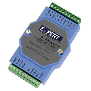
- 8 Isolated PhotoMOS Relay Outputs: Each channel provides a normally open (Form A) contact configuration, suitable for controlling AC or DC loads up to 350 VAC (peak) or 0.13 A (peak).
- High-Speed Switching: Turn-on time of 0.7 ms and turn-off time of 0.05 ms enable rapid response for time-critical control applications.
- High Isolation Voltage: 5000 VAC isolation between channels and logic circuitry ensures robust protection against electrical noise and surges.
- RS-485 Communication Interface: Two-wire serial interface supporting multiple baud rates (1200 bps to 115.2 kbps) for long-distance, multi-drop communication.
- Modbus RTU Protocol Support: Fully compatible with Modbus RTU standard for seamless integration with PLCs, SCADA systems, and industrial controllers.
- Dual Watchdog Timer: Hardware (module) and software (host) watchdogs ensure continuous operation and fail-safe behavior in case of communication loss or system fault.
- LED Indicators: Eight channel LEDs provide real-time output status visualization for easy diagnostics.
- Wide Power Supply Range: Operates from +10 VDC to +30 VDC, suitable for diverse industrial power environments.
- Compact and Rugged Design: Engineered for harsh industrial conditions with an operating temperature range of -25 °C to +75 °C.
- EEPROM Configuration Storage: Retains module address, baud rate, and protocol settings even after power loss.
- INIT* Mode for Configuration Recovery: Allows resetting or reconfiguring communication parameters when module settings are unknown.
- Safe and Power-On Values: User-definable output states for startup and fault conditions to ensure predictable system behavior.
- High-Speed Switching: Turn-on time of 0.7 ms and turn-off time of 0.05 ms enable rapid response for time-critical control applications.
- High Isolation Voltage: 5000 VAC isolation between channels and logic circuitry ensures robust protection against electrical noise and surges.
- RS-485 Communication Interface: Two-wire serial interface supporting multiple baud rates (1200 bps to 115.2 kbps) for long-distance, multi-drop communication.
- Modbus RTU Protocol Support: Fully compatible with Modbus RTU standard for seamless integration with PLCs, SCADA systems, and industrial controllers.
- Dual Watchdog Timer: Hardware (module) and software (host) watchdogs ensure continuous operation and fail-safe behavior in case of communication loss or system fault.
- LED Indicators: Eight channel LEDs provide real-time output status visualization for easy diagnostics.
- Wide Power Supply Range: Operates from +10 VDC to +30 VDC, suitable for diverse industrial power environments.
- Compact and Rugged Design: Engineered for harsh industrial conditions with an operating temperature range of -25 °C to +75 °C.
- EEPROM Configuration Storage: Retains module address, baud rate, and protocol settings even after power loss.
- INIT* Mode for Configuration Recovery: Allows resetting or reconfiguring communication parameters when module settings are unknown.
- Safe and Power-On Values: User-definable output states for startup and fault conditions to ensure predictable system behavior.
Comprehensive Product Summary – EX9068AD-M
### 1. Product Overview
Product Name: EX9068AD-M
Article Number: EX9068AD-M
Series: EX9000 Series Digital I/O Modules
Model Type: 8-Channel Isolated PhotoMOS Relay Output Module
Manufacturer: EX Industrial Automation (EX Series I/O Systems)
The EX9068AD-M is a high-performance, isolated digital output module designed for industrial automation and control systems. It provides eight independent PhotoMOS relay output channels with high isolation, fast switching, and Modbus RTU communication over RS-485. The module is part of the EX9000 series, which supports distributed I/O control via serial communication networks. It is optimized for applications requiring precise, low-level analog signal switching without distortion, such as high-speed inspection systems, telecommunications, and data communication equipment.
### 2. Key Features
- 8 Isolated PhotoMOS Relay Outputs: Each channel provides a normally open (Form A) contact configuration, suitable for controlling AC or DC loads up to 350 VAC (peak) or 0.13 A (peak).
- High-Speed Switching: Turn-on time of 0.7 ms and turn-off time of 0.05 ms enable rapid response for time-critical control applications.
- High Isolation Voltage: 5000 VAC isolation between channels and logic circuitry ensures robust protection against electrical noise and surges.
- RS-485 Communication Interface: Two-wire serial interface supporting multiple baud rates (1200 bps to 115.2 kbps) for long-distance, multi-drop communication.
- Modbus RTU Protocol Support: Fully compatible with Modbus RTU standard for seamless integration with PLCs, SCADA systems, and industrial controllers.
- Dual Watchdog Timer: Hardware (module) and software (host) watchdogs ensure continuous operation and fail-safe behavior in case of communication loss or system fault.
- LED Indicators: Eight channel LEDs provide real-time output status visualization for easy diagnostics.
- Wide Power Supply Range: Operates from +10 VDC to +30 VDC, suitable for diverse industrial power environments.
- Compact and Rugged Design: Engineered for harsh industrial conditions with an operating temperature range of -25 °C to +75 °C.
- EEPROM Configuration Storage: Retains module address, baud rate, and protocol settings even after power loss.
- INIT* Mode for Configuration Recovery: Allows resetting or reconfiguring communication parameters when module settings are unknown.
- Safe and Power-On Values: User-definable output states for startup and fault conditions to ensure predictable system behavior.
### 3. Technical Specifications
| Parameter | Specification |
|----------------|-------------------|
| Digital Output Channels | 8 isolated PhotoMOS relay outputs (Form A, normally open) |
| Output Type | Solid-state PhotoMOS relay |
| Turn-On Time | 0.7 ms |
| Turn-Off Time | 0.05 ms |
| Output Resistance | 23 Ω |
| I/O Capacitance | 0.8 pF (at 1 MHz) |
| Output Voltage Range | 0 – 350 VAC (peak) |
| Output Current Range | 0 – 0.13 A (peak) |
| Isolation Voltage | 5000 VAC |
| Interface | RS-485, 2-wire |
| Communication Speed | 1200, 2400, 4800, 9600, 19.2 k, 38.4 k, 57.6 k, 115.2 k bps |
| Protocol | Modbus RTU (default), ASCII command mode available |
| Power Supply | +10 VDC – +30 VDC |
| Power Consumption | 1.4 W typical |
| Operating Temperature | -25 °C – +75 °C |
| Storage Temperature | -30 °C – +75 °C |
| Surge Strength | 1500 V |
| Minimum Life Expectancy | 10⁵ operations |
| LED Indicators | 8 output status LEDs |
| Isolation Type | Optical isolation between field and logic circuits |
| Mounting | DIN-rail or panel mount (depending on enclosure) |
| Housing Material | Industrial-grade ABS or polycarbonate enclosure |
| Dimensions / Weight | Compact modular form factor (typical EX9000 series dimensions: approx. 72 mm × 118 mm × 39 mm; weight ~150 g) |
### 4. Functionality
The EX9068AD-M functions as an 8-channel digital output module that uses PhotoMOS relays to switch external loads. Each output channel operates independently and is electrically isolated from the others, allowing control of multiple circuits without interference.
Operation Principle:
- The host controller communicates with the module via RS-485 using Modbus RTU or ASCII commands.
- Each output channel can be turned ON or OFF through Modbus function codes or ASCII commands.
- The module’s internal microcontroller interprets commands and drives the PhotoMOS relays accordingly.
- LED indicators reflect the ON/OFF state of each output channel in real time.
Use Cases and Applications:
- Industrial Automation: Control of solenoids, indicators, and low-power actuators.
- Telecommunication Systems: Switching of analog signal lines without distortion.
- Data Communication Equipment: Signal routing and isolation.
- High-Speed Inspection Systems: Rapid switching for test and measurement setups.
- Remote I/O Expansion: Distributed control in SCADA and DCS systems.
Compatibility:
- Compatible with Modbus RTU master devices such as PLCs, HMIs, and industrial PCs.
- Integrates with EX9000 series modules for mixed I/O configurations.
- Supports ASCII command mode for direct serial control and configuration.
### 5. Components & Accessories
Included Components:
- EX9068AD-M module unit
- Terminal block connectors for power and signal wiring
- Quick start guide and configuration instructions
Optional Accessories:
- RS-485 communication cables
- DIN-rail mounting brackets
- Power supply adapters (24 VDC recommended)
- Configuration utility software (EX9000 Utility)
Connectors:
- RS-485 Port: 2-wire differential signal (A/B lines)
- Power Input Terminal: +VDC and GND
- Output Terminals: 8 channel outputs with individual commons
### 6. Installation & Setup
Requirements:
- Power supply: +10 VDC to +30 VDC (regulated, ripple < 50 mV)
- RS-485 network connection with proper termination resistors
- Host controller supporting Modbus RTU or ASCII protocol
Mounting Options:
- DIN-rail mounting (standard for EX9000 series)
- Panel mounting via screw holes (optional)
Configuration Steps:
1. Default Settings:
- Module Address: 01
- DIO Type: 40
- Baud Rate: 9600 bps
- Protocol: Modbus RTU
2. INIT* Mode Activation:
- Connect INIT* pin to GND before power-on to enter configuration mode.
- In INIT* mode, the module address is set to 00 and baud rate to 9600 bps (no checksum).
- Use ASCII commands to modify address, baud rate, or protocol.
3. Setting Communication Parameters:
- Use command `%AANNTTCCFF` to set address, type, baud rate, and data format.
- Configuration is stored in EEPROM and becomes effective after power cycling.
4. Wiring:
- Connect RS-485 A/B lines to the network bus.
- Connect power supply to +VDC and GND terminals.
- Connect load devices to output terminals (observe voltage/current limits).
5. Verification:
- Power on the module and verify LED indicators.
- Use Modbus or ASCII commands to test output switching.
### 7. Performance & Capabilities
Switching Performance:
- Fast response with 0.7 ms turn-on and 0.05 ms turn-off times.
- Suitable for high-frequency switching of low-level analog or digital signals.
Load Capacity:
- Supports up to 350 VAC (peak) or 0.13 A (peak) per channel.
- Designed for low-current control applications rather than high-power loads.
Reliability:
- Dual watchdog system ensures continuous operation:
- Module Watchdog: Hardware circuit monitors internal operation and resets the module if a fault occurs.
- Host Watchdog: Software timer monitors communication; if timeout occurs, outputs revert to predefined safe values.
Efficiency:
- Low power consumption (1.4 W typical) allows dense installation in control cabinets.
- High isolation minimizes interference and ground loop issues.
Limitations:
- Not intended for high-current or inductive loads exceeding 0.13 A.
- Requires external suppression for inductive loads if used near rated limits.
### 8. Standards & Compliance
Communication Standards:
- RS-485 (EIA/TIA-485) compliant differential serial interface.
- Modbus RTU protocol compliant with Modbus Organization specifications.
Electrical Safety & Isolation:
- 5000 VAC isolation between field and logic circuits.
- Surge strength up to 1500 V.
Environmental Compliance:
- Operating temperature: -25 °C to +75 °C
- Storage temperature: -30 °C to +75 °C
- Designed for industrial environments with electrical noise immunity.
Quality & Reliability:
- EEPROM-based configuration retention.
- Minimum mechanical/electrical life: 100,000 operations.
Regulatory Compliance (typical for EX9000 series):
- CE (EMC and Low Voltage Directive)
- RoHS compliant materials
- Industrial-grade design for EN 61000-6-2/4 EMC standards
### 9. Additional Information
Warranty:
Standard manufacturer warranty (typically 1–2 years) covering defects in materials and workmanship under normal operating conditions.
Technical Support:
- Configuration utilities and documentation available from manufacturer’s website.
- Firmware updates and Modbus mapping tables provided for integration support.
- Technical assistance via email or online support portal.
Maintenance:
- No mechanical contacts; PhotoMOS relays require minimal maintenance.
- Periodic inspection of wiring and terminal connections recommended.
- Firmware and configuration can be updated via RS-485 interface.
Firmware & Updates:
- Firmware version readable via command `$AAF`.
- Example: `$01F` → `!01D03.11` (indicating firmware version D03.11).
- Updates may include enhanced Modbus mapping or watchdog features.
Safety & Reliability Features:
- Safe Value: Defines output state when host communication fails.
- Power-On Value: Defines output state upon startup or reset.
- Reset Status Monitoring: `$AA5` command allows checking if module has been reset.
- EEPROM Configuration Storage: Ensures persistent settings across power cycles.
Modbus Function Codes Supported:
- 0x01: Read Digital Output Value
- 0x05: Write Single Digital Output
- 0x0F: Write Multiple Digital Outputs
- 0x03: Read Configuration and WDT Values
- 0x06: Set WDT Timeout Value
Modbus Register Mapping (Summary):
- DO Channels: 00001–00008 (R/W)
- Safe Values: 00129–00136 (R/W)
- Power-On Values: 00161–00168 (R/W)
- WDT Timeout Value: 40489 (R/W)
- WDT Enable/Disable: 00261 (R/W)
- WDT Timeout Status: 00270 (R/W)
- Module Address: 40485 (R/W)
- Baud Rate: 40486 (R/W)
- Module Name: 40483–40484 (R)
Host Watchdog Configuration:
- Timeout value adjustable from 0.1 s to 25.5 s (01–FF hex).
- Commands `~AA3EVV` and `~AA2` used to set and read timeout values.
- Host sends periodic `~` command to indicate “Host OK” status.
INIT* Mode Recovery:
- Used when communication parameters are lost.
- Entered by connecting INIT* pin to GND before power-on.
- Allows reading and resetting of configuration via ASCII commands.
### Summary
The EX9068AD-M** is a robust, high-isolation, 8-channel PhotoMOS relay output module designed for industrial automation systems requiring reliable, noise-immune, and fast digital output control. Its combination of Modbus RTU communication, dual watchdog protection, and flexible configuration options make it ideal for distributed control networks and precision signal switching applications. With a wide operating voltage range, compact design, and comprehensive Modbus mapping, the EX9068AD-M delivers dependable performance in demanding industrial environments while maintaining ease of integration and long-term reliability.
### 1. Product Overview
Product Name: EX9068AD-M
Article Number: EX9068AD-M
Series: EX9000 Series Digital I/O Modules
Model Type: 8-Channel Isolated PhotoMOS Relay Output Module
Manufacturer: EX Industrial Automation (EX Series I/O Systems)
The EX9068AD-M is a high-performance, isolated digital output module designed for industrial automation and control systems. It provides eight independent PhotoMOS relay output channels with high isolation, fast switching, and Modbus RTU communication over RS-485. The module is part of the EX9000 series, which supports distributed I/O control via serial communication networks. It is optimized for applications requiring precise, low-level analog signal switching without distortion, such as high-speed inspection systems, telecommunications, and data communication equipment.
### 2. Key Features
- 8 Isolated PhotoMOS Relay Outputs: Each channel provides a normally open (Form A) contact configuration, suitable for controlling AC or DC loads up to 350 VAC (peak) or 0.13 A (peak).
- High-Speed Switching: Turn-on time of 0.7 ms and turn-off time of 0.05 ms enable rapid response for time-critical control applications.
- High Isolation Voltage: 5000 VAC isolation between channels and logic circuitry ensures robust protection against electrical noise and surges.
- RS-485 Communication Interface: Two-wire serial interface supporting multiple baud rates (1200 bps to 115.2 kbps) for long-distance, multi-drop communication.
- Modbus RTU Protocol Support: Fully compatible with Modbus RTU standard for seamless integration with PLCs, SCADA systems, and industrial controllers.
- Dual Watchdog Timer: Hardware (module) and software (host) watchdogs ensure continuous operation and fail-safe behavior in case of communication loss or system fault.
- LED Indicators: Eight channel LEDs provide real-time output status visualization for easy diagnostics.
- Wide Power Supply Range: Operates from +10 VDC to +30 VDC, suitable for diverse industrial power environments.
- Compact and Rugged Design: Engineered for harsh industrial conditions with an operating temperature range of -25 °C to +75 °C.
- EEPROM Configuration Storage: Retains module address, baud rate, and protocol settings even after power loss.
- INIT* Mode for Configuration Recovery: Allows resetting or reconfiguring communication parameters when module settings are unknown.
- Safe and Power-On Values: User-definable output states for startup and fault conditions to ensure predictable system behavior.
### 3. Technical Specifications
| Parameter | Specification |
|----------------|-------------------|
| Digital Output Channels | 8 isolated PhotoMOS relay outputs (Form A, normally open) |
| Output Type | Solid-state PhotoMOS relay |
| Turn-On Time | 0.7 ms |
| Turn-Off Time | 0.05 ms |
| Output Resistance | 23 Ω |
| I/O Capacitance | 0.8 pF (at 1 MHz) |
| Output Voltage Range | 0 – 350 VAC (peak) |
| Output Current Range | 0 – 0.13 A (peak) |
| Isolation Voltage | 5000 VAC |
| Interface | RS-485, 2-wire |
| Communication Speed | 1200, 2400, 4800, 9600, 19.2 k, 38.4 k, 57.6 k, 115.2 k bps |
| Protocol | Modbus RTU (default), ASCII command mode available |
| Power Supply | +10 VDC – +30 VDC |
| Power Consumption | 1.4 W typical |
| Operating Temperature | -25 °C – +75 °C |
| Storage Temperature | -30 °C – +75 °C |
| Surge Strength | 1500 V |
| Minimum Life Expectancy | 10⁵ operations |
| LED Indicators | 8 output status LEDs |
| Isolation Type | Optical isolation between field and logic circuits |
| Mounting | DIN-rail or panel mount (depending on enclosure) |
| Housing Material | Industrial-grade ABS or polycarbonate enclosure |
| Dimensions / Weight | Compact modular form factor (typical EX9000 series dimensions: approx. 72 mm × 118 mm × 39 mm; weight ~150 g) |
### 4. Functionality
The EX9068AD-M functions as an 8-channel digital output module that uses PhotoMOS relays to switch external loads. Each output channel operates independently and is electrically isolated from the others, allowing control of multiple circuits without interference.
Operation Principle:
- The host controller communicates with the module via RS-485 using Modbus RTU or ASCII commands.
- Each output channel can be turned ON or OFF through Modbus function codes or ASCII commands.
- The module’s internal microcontroller interprets commands and drives the PhotoMOS relays accordingly.
- LED indicators reflect the ON/OFF state of each output channel in real time.
Use Cases and Applications:
- Industrial Automation: Control of solenoids, indicators, and low-power actuators.
- Telecommunication Systems: Switching of analog signal lines without distortion.
- Data Communication Equipment: Signal routing and isolation.
- High-Speed Inspection Systems: Rapid switching for test and measurement setups.
- Remote I/O Expansion: Distributed control in SCADA and DCS systems.
Compatibility:
- Compatible with Modbus RTU master devices such as PLCs, HMIs, and industrial PCs.
- Integrates with EX9000 series modules for mixed I/O configurations.
- Supports ASCII command mode for direct serial control and configuration.
### 5. Components & Accessories
Included Components:
- EX9068AD-M module unit
- Terminal block connectors for power and signal wiring
- Quick start guide and configuration instructions
Optional Accessories:
- RS-485 communication cables
- DIN-rail mounting brackets
- Power supply adapters (24 VDC recommended)
- Configuration utility software (EX9000 Utility)
Connectors:
- RS-485 Port: 2-wire differential signal (A/B lines)
- Power Input Terminal: +VDC and GND
- Output Terminals: 8 channel outputs with individual commons
### 6. Installation & Setup
Requirements:
- Power supply: +10 VDC to +30 VDC (regulated, ripple < 50 mV)
- RS-485 network connection with proper termination resistors
- Host controller supporting Modbus RTU or ASCII protocol
Mounting Options:
- DIN-rail mounting (standard for EX9000 series)
- Panel mounting via screw holes (optional)
Configuration Steps:
1. Default Settings:
- Module Address: 01
- DIO Type: 40
- Baud Rate: 9600 bps
- Protocol: Modbus RTU
2. INIT* Mode Activation:
- Connect INIT* pin to GND before power-on to enter configuration mode.
- In INIT* mode, the module address is set to 00 and baud rate to 9600 bps (no checksum).
- Use ASCII commands to modify address, baud rate, or protocol.
3. Setting Communication Parameters:
- Use command `%AANNTTCCFF` to set address, type, baud rate, and data format.
- Configuration is stored in EEPROM and becomes effective after power cycling.
4. Wiring:
- Connect RS-485 A/B lines to the network bus.
- Connect power supply to +VDC and GND terminals.
- Connect load devices to output terminals (observe voltage/current limits).
5. Verification:
- Power on the module and verify LED indicators.
- Use Modbus or ASCII commands to test output switching.
### 7. Performance & Capabilities
Switching Performance:
- Fast response with 0.7 ms turn-on and 0.05 ms turn-off times.
- Suitable for high-frequency switching of low-level analog or digital signals.
Load Capacity:
- Supports up to 350 VAC (peak) or 0.13 A (peak) per channel.
- Designed for low-current control applications rather than high-power loads.
Reliability:
- Dual watchdog system ensures continuous operation:
- Module Watchdog: Hardware circuit monitors internal operation and resets the module if a fault occurs.
- Host Watchdog: Software timer monitors communication; if timeout occurs, outputs revert to predefined safe values.
Efficiency:
- Low power consumption (1.4 W typical) allows dense installation in control cabinets.
- High isolation minimizes interference and ground loop issues.
Limitations:
- Not intended for high-current or inductive loads exceeding 0.13 A.
- Requires external suppression for inductive loads if used near rated limits.
### 8. Standards & Compliance
Communication Standards:
- RS-485 (EIA/TIA-485) compliant differential serial interface.
- Modbus RTU protocol compliant with Modbus Organization specifications.
Electrical Safety & Isolation:
- 5000 VAC isolation between field and logic circuits.
- Surge strength up to 1500 V.
Environmental Compliance:
- Operating temperature: -25 °C to +75 °C
- Storage temperature: -30 °C to +75 °C
- Designed for industrial environments with electrical noise immunity.
Quality & Reliability:
- EEPROM-based configuration retention.
- Minimum mechanical/electrical life: 100,000 operations.
Regulatory Compliance (typical for EX9000 series):
- CE (EMC and Low Voltage Directive)
- RoHS compliant materials
- Industrial-grade design for EN 61000-6-2/4 EMC standards
### 9. Additional Information
Warranty:
Standard manufacturer warranty (typically 1–2 years) covering defects in materials and workmanship under normal operating conditions.
Technical Support:
- Configuration utilities and documentation available from manufacturer’s website.
- Firmware updates and Modbus mapping tables provided for integration support.
- Technical assistance via email or online support portal.
Maintenance:
- No mechanical contacts; PhotoMOS relays require minimal maintenance.
- Periodic inspection of wiring and terminal connections recommended.
- Firmware and configuration can be updated via RS-485 interface.
Firmware & Updates:
- Firmware version readable via command `$AAF`.
- Example: `$01F` → `!01D03.11` (indicating firmware version D03.11).
- Updates may include enhanced Modbus mapping or watchdog features.
Safety & Reliability Features:
- Safe Value: Defines output state when host communication fails.
- Power-On Value: Defines output state upon startup or reset.
- Reset Status Monitoring: `$AA5` command allows checking if module has been reset.
- EEPROM Configuration Storage: Ensures persistent settings across power cycles.
Modbus Function Codes Supported:
- 0x01: Read Digital Output Value
- 0x05: Write Single Digital Output
- 0x0F: Write Multiple Digital Outputs
- 0x03: Read Configuration and WDT Values
- 0x06: Set WDT Timeout Value
Modbus Register Mapping (Summary):
- DO Channels: 00001–00008 (R/W)
- Safe Values: 00129–00136 (R/W)
- Power-On Values: 00161–00168 (R/W)
- WDT Timeout Value: 40489 (R/W)
- WDT Enable/Disable: 00261 (R/W)
- WDT Timeout Status: 00270 (R/W)
- Module Address: 40485 (R/W)
- Baud Rate: 40486 (R/W)
- Module Name: 40483–40484 (R)
Host Watchdog Configuration:
- Timeout value adjustable from 0.1 s to 25.5 s (01–FF hex).
- Commands `~AA3EVV` and `~AA2` used to set and read timeout values.
- Host sends periodic `~` command to indicate “Host OK” status.
INIT* Mode Recovery:
- Used when communication parameters are lost.
- Entered by connecting INIT* pin to GND before power-on.
- Allows reading and resetting of configuration via ASCII commands.
### Summary
The EX9068AD-M** is a robust, high-isolation, 8-channel PhotoMOS relay output module designed for industrial automation systems requiring reliable, noise-immune, and fast digital output control. Its combination of Modbus RTU communication, dual watchdog protection, and flexible configuration options make it ideal for distributed control networks and precision signal switching applications. With a wide operating voltage range, compact design, and comprehensive Modbus mapping, the EX9068AD-M delivers dependable performance in demanding industrial environments while maintaining ease of integration and long-term reliability.

No accessories available.