
 LOOKING FOR THE RIGHT
INDUSTRIAL SOLUTION?
Discover embedded, communication and automation solutions tailored to your application.
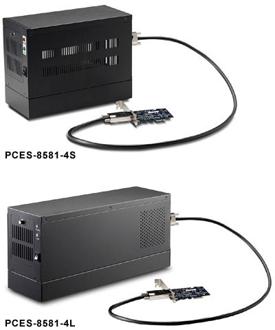
- PCI Express‑based Control of PCI Devices:
Provides seamless PCI bus expansion via a PCIe x1 interface, enabling remote management of PCI cards.
- High‑Speed PCI Express x1 Interface:
Supports 2.5 Gb/s signaling rate per direction with 250 MB/s data throughput.
- Full Hardware and Software Transparency:
No additional drivers or software required; devices appear natively to the host BIOS and OS.
- Compatibility:
Supports both 5 V and 3.3 V PCI signaling; compliant with 32‑bit/33 MHz PCI interface.
- Expansion Capacity:
- PCES‑8581‑4S / 4L: Four half‑size PCI slots in a compact wall‑mount chassis with integrated 200 W PSU.
- PCES‑8581‑13S: Thirteen full‑size PCI slots in a 19‑inch rackmount chassis with 400 W PSU.
- Extended Distance Operation:
Supports cable lengths of 1 m, 3 m, and 7 m between host and expansion chassis.
- Environmental Robustness:
Designed for industrial, test, and measurement environments with high vibration or temperature extremes.
- Standards Compliance:
- PCI Express® Base Specification Rev. 1.0a
- PCI‑to‑PCI Bridge Architecture Specification Rev. 1.2
- PCI Local Bus Specification Rev. 3.0
- Integrated Cooling:
High‑efficiency ball‑bearing fans ensure stable thermal performance.
- Remote Power‑On/Off Capability:
Optional remote power control via backplane connectors (BP‑8014).
Provides seamless PCI bus expansion via a PCIe x1 interface, enabling remote management of PCI cards.
- High‑Speed PCI Express x1 Interface:
Supports 2.5 Gb/s signaling rate per direction with 250 MB/s data throughput.
- Full Hardware and Software Transparency:
No additional drivers or software required; devices appear natively to the host BIOS and OS.
- Compatibility:
Supports both 5 V and 3.3 V PCI signaling; compliant with 32‑bit/33 MHz PCI interface.
- Expansion Capacity:
- PCES‑8581‑4S / 4L: Four half‑size PCI slots in a compact wall‑mount chassis with integrated 200 W PSU.
- PCES‑8581‑13S: Thirteen full‑size PCI slots in a 19‑inch rackmount chassis with 400 W PSU.
- Extended Distance Operation:
Supports cable lengths of 1 m, 3 m, and 7 m between host and expansion chassis.
- Environmental Robustness:
Designed for industrial, test, and measurement environments with high vibration or temperature extremes.
- Standards Compliance:
- PCI Express® Base Specification Rev. 1.0a
- PCI‑to‑PCI Bridge Architecture Specification Rev. 1.2
- PCI Local Bus Specification Rev. 3.0
- Integrated Cooling:
High‑efficiency ball‑bearing fans ensure stable thermal performance.
- Remote Power‑On/Off Capability:
Optional remote power control via backplane connectors (BP‑8014).
Comprehensive Product Summary – ADLINK PCES‑8581‑4L / PCES‑8581‑4S PCIe‑to‑PCI Expansion System
### 1. Product Overview
Product Name: PCI Express‑to‑PCI Expansion System
Model: PCES‑8581‑4L (equivalent to PCES‑8581‑4S series)
Series: PCES‑8581‑4S / PCES‑8581‑13S Expansion Systems
Article Number: PCES‑8581‑4L
Manufacturer: ADLINK Technology Inc.
Associated Components: PCIe‑8560 host card, PCI‑8565 bridge card, RK‑8005L 4‑slot expansion chassis, ACL‑EXPRESS‑3 cable
The ADLINK PCES‑8581‑4L is a high‑performance PCI Express‑to‑PCI expansion system designed to extend the PCI bus architecture of a host computer through a PCI Express (PCIe) interface. It enables a host PC equipped with a PCIe slot to control and operate up to four full‑size PCI cards remotely, using a shielded high‑speed cable connection. The system provides complete hardware and software transparency, allowing PCI devices in the expansion chassis to function as if they were installed directly in the host system.
### 2. Key Features
- PCI Express‑based Control of PCI Devices:
Provides seamless PCI bus expansion via a PCIe x1 interface, enabling remote management of PCI cards.
- High‑Speed PCI Express x1 Interface:
Supports 2.5 Gb/s signaling rate per direction with 250 MB/s data throughput.
- Full Hardware and Software Transparency:
No additional drivers or software required; devices appear natively to the host BIOS and OS.
- Compatibility:
Supports both 5 V and 3.3 V PCI signaling; compliant with 32‑bit/33 MHz PCI interface.
- Expansion Capacity:
- PCES‑8581‑4S / 4L: Four half‑size PCI slots in a compact wall‑mount chassis with integrated 200 W PSU.
- PCES‑8581‑13S: Thirteen full‑size PCI slots in a 19‑inch rackmount chassis with 400 W PSU.
- Extended Distance Operation:
Supports cable lengths of 1 m, 3 m, and 7 m between host and expansion chassis.
- Environmental Robustness:
Designed for industrial, test, and measurement environments with high vibration or temperature extremes.
- Standards Compliance:
- PCI Express® Base Specification Rev. 1.0a
- PCI‑to‑PCI Bridge Architecture Specification Rev. 1.2
- PCI Local Bus Specification Rev. 3.0
- Integrated Cooling:
High‑efficiency ball‑bearing fans ensure stable thermal performance.
- Remote Power‑On/Off Capability:
Optional remote power control via backplane connectors (BP‑8014).
### 3. Technical Specifications
Host Interface Card – PCIe‑8560
- Compliance: PCI Express Base Specification Rev. 1.0a
- Interface: PCIe x1 link, 2.5 Gb/s per direction (250 MB/s throughput)
- Dimensions: 69 mm (H) × 87 mm (W) (2.69 × 3.39 in)
- Power Requirement: +3.3 V @ 210 mA
- Form Factor: Low‑profile PCIe card
- Connectors: PCIe serial link connector (CN1), signal equalizer jumpers (S1/S2)
- Indicators: Serial link status LED (D1)
Bridge Card – PCI‑8565
- Compliance: PCI‑to‑PCI Bridge Architecture Rev. 1.2; PCI Local Bus Rev. 3.0
- Bus Support: 32‑bit/33 MHz PCI, 5 V and 3.3 V signaling
- Dimensions: 64 mm (H) × 120 mm (W) (2.49 × 4.68 in)
- Power Requirement: +3.3 V @ 720 mA
- Connectors: PCIe serial link connector (CN1), JP1 (remote power‑on), JP2 (spread spectrum control)
- Indicators: Serial link status LED (D1)
Expansion Chassis – RK‑8005 (4‑Slot)
- Dimensions: 122 mm (W) × 195 mm (H) × 259 mm (D) (4.75 × 7.6 × 10.1 in)
- Weight: 3.2 kg (7.04 lb)
- Backplane: Five 32‑bit/33 MHz half‑size PCI slots (1 system slot for PCI‑8565, 4 available PCI slots)
- Power Supply: 200 W, 85–265 V AC input, auto‑switching
- Cooling: One 80 mm ball‑bearing fan, 37.5 CFM airflow
- Mounting: Wall‑mount kit included
Expansion Chassis – RK‑8014 (13‑Slot)
- Dimensions: 483.5 mm (W) × 177 mm (H) × 448.5 mm (D) (18.85 × 6.9 × 17.5 in)
- Weight: 12 kg (26.4 lb)
- Backplane: 14 × 32‑bit/33 MHz full‑size PCI slots (1 system slot for PCI‑8565, 13 available PCI slots)
- Power Supply: 400 W, 85–265 V AC input, auto‑switching
- Cooling: Two 120 mm ball‑bearing fans, 88 CFM each
- Mounting: 19‑inch rackmount
Environmental Conditions
- Operating Temperature: 0 °C to 50 °C (32 °F to 122 °F)
- Storage Temperature: −20 °C to 80 °C (−4 °F to 176 °F)
- Relative Humidity: 10 % to 90 %, non‑condensing
### 4. Functionality
The PCES‑8581‑4L system extends a host computer’s PCI bus through a PCI Express x1 interface. The PCIe‑8560 card installed in the host PC communicates with the PCI‑8565 bridge card in the remote chassis via a shielded twisted‑pair copper cable. The PCI‑8565 converts the PCIe signal into a standard PCI bus, enabling the remote chassis to host multiple PCI devices.
Operation Principle:
- The PCIe‑8560 transmits differential signals through the cable to the PCI‑8565.
- The PCI‑8565 bridges the PCIe link to a 32‑bit/33 MHz PCI bus on the backplane.
- The host BIOS enumerates all PCI devices in the remote chassis as if they were local.
- No additional drivers or software are required.
Use Cases and Applications:
- Industrial automation and control systems
- High‑density data acquisition (DAQ) and I/O expansion
- Test and measurement setups requiring remote PCI device placement
- Military and aerospace electronics testing
- Video capture and signal processing systems
- Environments requiring isolation from EMI or hazardous conditions
Compatibility:
- Works with standard PCI devices (5 V or 3.3 V)
- Compatible with Windows, Linux, and other OSs supporting PCI enumeration
- Supports Intel‑based chipsets (945, 965, and later) for optimal BIOS resource allocation
### 5. Components & Accessories
Included Items (PCES‑8581‑4S / 4L):
- 1 × PCIe‑8560 host card
- 1 × RK‑8005 expansion chassis (pre‑installed PCI‑8565 and backplane)
- 1 × ACL‑EXPRESS‑3 cable (3 m)
- 1 × AC power cord
- 1 × Wall‑mount kit
- 1 × User manual
Optional Accessories:
- ACL‑EXPRESS‑1: 1 m PCIe‑to‑PCI extension cable
- ACL‑EXPRESS‑3: 3 m PCIe‑to‑PCI extension cable
- ACL‑EXPRESS‑7: 7 m PCIe‑to‑PCI extension cable
- Remote power‑on cable (for RK‑8014)
Connectors and Jumpers:
- PCIe‑8560: CN1 (serial link), S1/S2 (equalizer), D1 (status LED)
- PCI‑8565: CN1 (serial link), JP1 (remote power), JP2 (spread spectrum)
- BP‑8005: CN1–CN4 (LED, ATX power, fan, power‑OK), JP1–JP3 (LED, power enable, fan)
- BP‑8014: JP2 (ATX power enable), JP6 (power‑OK), FAN4–FAN6 (+12 V fans), CN2 (ATX power)
### 6. Installation & Setup
Requirements:
- Host PC with an available PCI Express x1 slot
- Stable power source (85–265 V AC)
- Anti‑static handling precautions
Installation Steps:
1. Power off the host PC and open the chassis.
2. Install the PCIe‑8560 card into an available PCIe x1 slot.
3. Mount the RK‑8005 expansion chassis in the desired location.
4. Connect the ACL‑EXPRESS cable between PCIe‑8560 (host) and PCI‑8565 (chassis).
5. Power on the expansion chassis first, then the host PC.
6. The BIOS automatically enumerates all PCI devices in the remote chassis.
Power‑On/Off Sequence:
- Power‑On: 1) Verify cable connection → 2) Power on chassis → 3) Power on host PC.
- Power‑Off: 1) Power off host PC → 2) Power off chassis.
Improper sequencing may cause system errors or data loss.
Remote Power Control (RK‑8014):
- Connect PCI‑8565 JP1 to BP‑8014 JP2 using the remote power cable.
- Enables synchronized power control from the host PC.
LED Indicators:
- LEDs on PCIe‑8560 and PCI‑8565 indicate link and power status.
- LEDs illuminate when the cable is connected, chassis powered, and host POST initiated.
### 7. Performance & Capabilities
- Bus Throughput: 32‑bit/33 MHz PCI bus, 133 MB/s theoretical bandwidth per slot.
- PCIe Link Speed: 2.5 Gb/s per direction (x1 lane).
- Cable Lengths: 1 m, 3 m, 7 m (up to 7 m without signal degradation).
- Signal Integrity: Adjustable equalization, amplification, and de‑emphasis on PCIe‑8560.
- Cooling Efficiency:
- RK‑8005: 37.5 CFM airflow
- RK‑8014: 2 × 88 CFM airflow
- Power Efficiency: Auto‑switching PSUs (200 W or 400 W) with ATX connectors and power‑OK signals.
- Limitations:
- One expansion chassis per PCIe‑8560 host card (point‑to‑point PCIe architecture).
- BIOS resource allocation may limit total PCI devices depending on host chipset.
### 8. Standards & Compliance
- PCI Express® Base Specification Rev. 1.0a
- PCI‑to‑PCI Bridge Architecture Specification Rev. 1.2
- PCI Local Bus Specification Rev. 3.0
- Electrical Safety: Designed for industrial environments, 85–265 V AC input range.
- EMI/EMC: Shielded twisted‑pair cable minimizes electromagnetic interference.
- Environmental Compliance: Operating 0–50 °C, non‑condensing humidity up to 90 %.
- Mechanical Standards:
- RK‑8005: Shoebox‑size wall‑mount chassis
- RK‑8014: 19‑inch rackmount chassis
### 9. Additional Information
Warranty:
- Standard two‑year limited warranty (one year in China).
- Covers manufacturing defects; excludes damage from misuse, improper installation, or environmental factors.
- RMA service available via [http://rma.adlinktech.com/policy/](http://rma.adlinktech.com/policy/).
Support & Service Contacts:
- Headquarters (Taiwan): service@adlinktech.com | +886‑2‑8226‑5877
- ADLINK America: info@adlinktech.com | +1‑866‑423‑5465
- ADLINK Europe: emea@adlinktech.com | +49‑211‑495‑5552
- ADLINK China (Beijing, Shanghai, Shenzhen): market@adlinkchina.com.cn
- ADLINK Japan: japan@adlinktech.com | +81‑3‑4455‑3722
- ADLINK Singapore: singapore@adlinktech.com | +65‑6844‑2261
Maintenance:
- Keep ventilation unobstructed; clean fans periodically.
- Handle cards with anti‑static precautions.
- Use only ADLINK‑approved cables and power supplies.
Software & Updates:
- No drivers required; BIOS automatically enumerates devices.
- Firmware updates not typically necessary due to transparent bridge architecture.
Safety Precautions:
- Disconnect power before installation or maintenance.
- Avoid exposure to moisture, high temperature, or vibration beyond specified limits.
- Use grounded anti‑static mats and wrist straps during handling.
### Summary
The ADLINK PCES‑8581‑4L / PCES‑8581‑4S PCIe‑to‑PCI Expansion System provides a robust, transparent, and high‑speed solution for extending PCI functionality through a PCI Express interface. With support for up to four half‑size PCI cards, a 200 W integrated power supply, and cable lengths up to 7 m, it is ideal for industrial automation, test and measurement, and environments requiring remote or isolated PCI device operation. Its compliance with PCI Express and PCI standards ensures broad compatibility, while its rugged design and comprehensive support make it a reliable choice for demanding embedded and laboratory applications.
### 1. Product Overview
Product Name: PCI Express‑to‑PCI Expansion System
Model: PCES‑8581‑4L (equivalent to PCES‑8581‑4S series)
Series: PCES‑8581‑4S / PCES‑8581‑13S Expansion Systems
Article Number: PCES‑8581‑4L
Manufacturer: ADLINK Technology Inc.
Associated Components: PCIe‑8560 host card, PCI‑8565 bridge card, RK‑8005L 4‑slot expansion chassis, ACL‑EXPRESS‑3 cable
The ADLINK PCES‑8581‑4L is a high‑performance PCI Express‑to‑PCI expansion system designed to extend the PCI bus architecture of a host computer through a PCI Express (PCIe) interface. It enables a host PC equipped with a PCIe slot to control and operate up to four full‑size PCI cards remotely, using a shielded high‑speed cable connection. The system provides complete hardware and software transparency, allowing PCI devices in the expansion chassis to function as if they were installed directly in the host system.
### 2. Key Features
- PCI Express‑based Control of PCI Devices:
Provides seamless PCI bus expansion via a PCIe x1 interface, enabling remote management of PCI cards.
- High‑Speed PCI Express x1 Interface:
Supports 2.5 Gb/s signaling rate per direction with 250 MB/s data throughput.
- Full Hardware and Software Transparency:
No additional drivers or software required; devices appear natively to the host BIOS and OS.
- Compatibility:
Supports both 5 V and 3.3 V PCI signaling; compliant with 32‑bit/33 MHz PCI interface.
- Expansion Capacity:
- PCES‑8581‑4S / 4L: Four half‑size PCI slots in a compact wall‑mount chassis with integrated 200 W PSU.
- PCES‑8581‑13S: Thirteen full‑size PCI slots in a 19‑inch rackmount chassis with 400 W PSU.
- Extended Distance Operation:
Supports cable lengths of 1 m, 3 m, and 7 m between host and expansion chassis.
- Environmental Robustness:
Designed for industrial, test, and measurement environments with high vibration or temperature extremes.
- Standards Compliance:
- PCI Express® Base Specification Rev. 1.0a
- PCI‑to‑PCI Bridge Architecture Specification Rev. 1.2
- PCI Local Bus Specification Rev. 3.0
- Integrated Cooling:
High‑efficiency ball‑bearing fans ensure stable thermal performance.
- Remote Power‑On/Off Capability:
Optional remote power control via backplane connectors (BP‑8014).
### 3. Technical Specifications
Host Interface Card – PCIe‑8560
- Compliance: PCI Express Base Specification Rev. 1.0a
- Interface: PCIe x1 link, 2.5 Gb/s per direction (250 MB/s throughput)
- Dimensions: 69 mm (H) × 87 mm (W) (2.69 × 3.39 in)
- Power Requirement: +3.3 V @ 210 mA
- Form Factor: Low‑profile PCIe card
- Connectors: PCIe serial link connector (CN1), signal equalizer jumpers (S1/S2)
- Indicators: Serial link status LED (D1)
Bridge Card – PCI‑8565
- Compliance: PCI‑to‑PCI Bridge Architecture Rev. 1.2; PCI Local Bus Rev. 3.0
- Bus Support: 32‑bit/33 MHz PCI, 5 V and 3.3 V signaling
- Dimensions: 64 mm (H) × 120 mm (W) (2.49 × 4.68 in)
- Power Requirement: +3.3 V @ 720 mA
- Connectors: PCIe serial link connector (CN1), JP1 (remote power‑on), JP2 (spread spectrum control)
- Indicators: Serial link status LED (D1)
Expansion Chassis – RK‑8005 (4‑Slot)
- Dimensions: 122 mm (W) × 195 mm (H) × 259 mm (D) (4.75 × 7.6 × 10.1 in)
- Weight: 3.2 kg (7.04 lb)
- Backplane: Five 32‑bit/33 MHz half‑size PCI slots (1 system slot for PCI‑8565, 4 available PCI slots)
- Power Supply: 200 W, 85–265 V AC input, auto‑switching
- Cooling: One 80 mm ball‑bearing fan, 37.5 CFM airflow
- Mounting: Wall‑mount kit included
Expansion Chassis – RK‑8014 (13‑Slot)
- Dimensions: 483.5 mm (W) × 177 mm (H) × 448.5 mm (D) (18.85 × 6.9 × 17.5 in)
- Weight: 12 kg (26.4 lb)
- Backplane: 14 × 32‑bit/33 MHz full‑size PCI slots (1 system slot for PCI‑8565, 13 available PCI slots)
- Power Supply: 400 W, 85–265 V AC input, auto‑switching
- Cooling: Two 120 mm ball‑bearing fans, 88 CFM each
- Mounting: 19‑inch rackmount
Environmental Conditions
- Operating Temperature: 0 °C to 50 °C (32 °F to 122 °F)
- Storage Temperature: −20 °C to 80 °C (−4 °F to 176 °F)
- Relative Humidity: 10 % to 90 %, non‑condensing
### 4. Functionality
The PCES‑8581‑4L system extends a host computer’s PCI bus through a PCI Express x1 interface. The PCIe‑8560 card installed in the host PC communicates with the PCI‑8565 bridge card in the remote chassis via a shielded twisted‑pair copper cable. The PCI‑8565 converts the PCIe signal into a standard PCI bus, enabling the remote chassis to host multiple PCI devices.
Operation Principle:
- The PCIe‑8560 transmits differential signals through the cable to the PCI‑8565.
- The PCI‑8565 bridges the PCIe link to a 32‑bit/33 MHz PCI bus on the backplane.
- The host BIOS enumerates all PCI devices in the remote chassis as if they were local.
- No additional drivers or software are required.
Use Cases and Applications:
- Industrial automation and control systems
- High‑density data acquisition (DAQ) and I/O expansion
- Test and measurement setups requiring remote PCI device placement
- Military and aerospace electronics testing
- Video capture and signal processing systems
- Environments requiring isolation from EMI or hazardous conditions
Compatibility:
- Works with standard PCI devices (5 V or 3.3 V)
- Compatible with Windows, Linux, and other OSs supporting PCI enumeration
- Supports Intel‑based chipsets (945, 965, and later) for optimal BIOS resource allocation
### 5. Components & Accessories
Included Items (PCES‑8581‑4S / 4L):
- 1 × PCIe‑8560 host card
- 1 × RK‑8005 expansion chassis (pre‑installed PCI‑8565 and backplane)
- 1 × ACL‑EXPRESS‑3 cable (3 m)
- 1 × AC power cord
- 1 × Wall‑mount kit
- 1 × User manual
Optional Accessories:
- ACL‑EXPRESS‑1: 1 m PCIe‑to‑PCI extension cable
- ACL‑EXPRESS‑3: 3 m PCIe‑to‑PCI extension cable
- ACL‑EXPRESS‑7: 7 m PCIe‑to‑PCI extension cable
- Remote power‑on cable (for RK‑8014)
Connectors and Jumpers:
- PCIe‑8560: CN1 (serial link), S1/S2 (equalizer), D1 (status LED)
- PCI‑8565: CN1 (serial link), JP1 (remote power), JP2 (spread spectrum)
- BP‑8005: CN1–CN4 (LED, ATX power, fan, power‑OK), JP1–JP3 (LED, power enable, fan)
- BP‑8014: JP2 (ATX power enable), JP6 (power‑OK), FAN4–FAN6 (+12 V fans), CN2 (ATX power)
### 6. Installation & Setup
Requirements:
- Host PC with an available PCI Express x1 slot
- Stable power source (85–265 V AC)
- Anti‑static handling precautions
Installation Steps:
1. Power off the host PC and open the chassis.
2. Install the PCIe‑8560 card into an available PCIe x1 slot.
3. Mount the RK‑8005 expansion chassis in the desired location.
4. Connect the ACL‑EXPRESS cable between PCIe‑8560 (host) and PCI‑8565 (chassis).
5. Power on the expansion chassis first, then the host PC.
6. The BIOS automatically enumerates all PCI devices in the remote chassis.
Power‑On/Off Sequence:
- Power‑On: 1) Verify cable connection → 2) Power on chassis → 3) Power on host PC.
- Power‑Off: 1) Power off host PC → 2) Power off chassis.
Improper sequencing may cause system errors or data loss.
Remote Power Control (RK‑8014):
- Connect PCI‑8565 JP1 to BP‑8014 JP2 using the remote power cable.
- Enables synchronized power control from the host PC.
LED Indicators:
- LEDs on PCIe‑8560 and PCI‑8565 indicate link and power status.
- LEDs illuminate when the cable is connected, chassis powered, and host POST initiated.
### 7. Performance & Capabilities
- Bus Throughput: 32‑bit/33 MHz PCI bus, 133 MB/s theoretical bandwidth per slot.
- PCIe Link Speed: 2.5 Gb/s per direction (x1 lane).
- Cable Lengths: 1 m, 3 m, 7 m (up to 7 m without signal degradation).
- Signal Integrity: Adjustable equalization, amplification, and de‑emphasis on PCIe‑8560.
- Cooling Efficiency:
- RK‑8005: 37.5 CFM airflow
- RK‑8014: 2 × 88 CFM airflow
- Power Efficiency: Auto‑switching PSUs (200 W or 400 W) with ATX connectors and power‑OK signals.
- Limitations:
- One expansion chassis per PCIe‑8560 host card (point‑to‑point PCIe architecture).
- BIOS resource allocation may limit total PCI devices depending on host chipset.
### 8. Standards & Compliance
- PCI Express® Base Specification Rev. 1.0a
- PCI‑to‑PCI Bridge Architecture Specification Rev. 1.2
- PCI Local Bus Specification Rev. 3.0
- Electrical Safety: Designed for industrial environments, 85–265 V AC input range.
- EMI/EMC: Shielded twisted‑pair cable minimizes electromagnetic interference.
- Environmental Compliance: Operating 0–50 °C, non‑condensing humidity up to 90 %.
- Mechanical Standards:
- RK‑8005: Shoebox‑size wall‑mount chassis
- RK‑8014: 19‑inch rackmount chassis
### 9. Additional Information
Warranty:
- Standard two‑year limited warranty (one year in China).
- Covers manufacturing defects; excludes damage from misuse, improper installation, or environmental factors.
- RMA service available via [http://rma.adlinktech.com/policy/](http://rma.adlinktech.com/policy/).
Support & Service Contacts:
- Headquarters (Taiwan): service@adlinktech.com | +886‑2‑8226‑5877
- ADLINK America: info@adlinktech.com | +1‑866‑423‑5465
- ADLINK Europe: emea@adlinktech.com | +49‑211‑495‑5552
- ADLINK China (Beijing, Shanghai, Shenzhen): market@adlinkchina.com.cn
- ADLINK Japan: japan@adlinktech.com | +81‑3‑4455‑3722
- ADLINK Singapore: singapore@adlinktech.com | +65‑6844‑2261
Maintenance:
- Keep ventilation unobstructed; clean fans periodically.
- Handle cards with anti‑static precautions.
- Use only ADLINK‑approved cables and power supplies.
Software & Updates:
- No drivers required; BIOS automatically enumerates devices.
- Firmware updates not typically necessary due to transparent bridge architecture.
Safety Precautions:
- Disconnect power before installation or maintenance.
- Avoid exposure to moisture, high temperature, or vibration beyond specified limits.
- Use grounded anti‑static mats and wrist straps during handling.
### Summary
The ADLINK PCES‑8581‑4L / PCES‑8581‑4S PCIe‑to‑PCI Expansion System provides a robust, transparent, and high‑speed solution for extending PCI functionality through a PCI Express interface. With support for up to four half‑size PCI cards, a 200 W integrated power supply, and cable lengths up to 7 m, it is ideal for industrial automation, test and measurement, and environments requiring remote or isolated PCI device operation. Its compliance with PCI Express and PCI standards ensures broad compatibility, while its rugged design and comprehensive support make it a reliable choice for demanding embedded and laboratory applications.
-
 PCES-8581-4S_Datasheet_en_1.pdf
PDF Catalog
PCES-8581-4S_Datasheet_en_1.pdf
PDF Catalog
-
 PCES-8581-13S_Manual_2.pdf
Manual
PCES-8581-13S_Manual_2.pdf
Manual
No accessories available.

