DIN-68S-01
LOOKING FOR THE RIGHT
INDUSTRIAL SOLUTION?
Discover embedded, communication and automation solutions tailored to your application.
- High‑Resolution Data Acquisition:
24‑bit A/D conversion with up to 30 kS/s sampling rate for single‑channel operation.
4 differential load‑cell transducer inputs and 4 general‑purpose analog inputs.
- Integrated Motion Control:
3‑axis stepper/servo motor control with differential pulse outputs (CW/CCW or CLK/DIR).
Built‑in incremental encoder feedback channels for closed‑loop control.
- Precision Measurement:
Supports transducer sensitivities from 1.0 mV/V to 4.0 mV/V with 1/200,000 full‑scale accuracy.
Auto‑zero and remote‑sense functions for thermal drift and line‑loss compensation.
- Analog Output:
Two 16‑bit D/A channels with ±10 V output range and 5 kS/s update rate.
- Isolated Digital I/O:
8 opto‑isolated digital inputs (0–24 V) and 8 isolated MOSFET digital outputs (up to 300 mA sink current).
- Onboard Timing Resources:
Two 32‑bit 40 MHz general‑purpose timer/counters and two 4 MHz encoder inputs.
- Connectivity:
Dual 68‑pin VHDCI (SCSI‑II) connectors for analog, digital, and motion I/O.
- Plug‑and‑Play PCI Interface:
Fully compliant with 32‑bit 3.3 V/5 V PCI bus, supporting bus‑mastering DMA and scatter/gather transfers.
- Software Support:
Compatible with ADLINK PCIS‑DASK driver library for Windows 98/NT/2000/XP/Vista and LabVIEW™.
24‑bit A/D conversion with up to 30 kS/s sampling rate for single‑channel operation.
4 differential load‑cell transducer inputs and 4 general‑purpose analog inputs.
- Integrated Motion Control:
3‑axis stepper/servo motor control with differential pulse outputs (CW/CCW or CLK/DIR).
Built‑in incremental encoder feedback channels for closed‑loop control.
- Precision Measurement:
Supports transducer sensitivities from 1.0 mV/V to 4.0 mV/V with 1/200,000 full‑scale accuracy.
Auto‑zero and remote‑sense functions for thermal drift and line‑loss compensation.
- Analog Output:
Two 16‑bit D/A channels with ±10 V output range and 5 kS/s update rate.
- Isolated Digital I/O:
8 opto‑isolated digital inputs (0–24 V) and 8 isolated MOSFET digital outputs (up to 300 mA sink current).
- Onboard Timing Resources:
Two 32‑bit 40 MHz general‑purpose timer/counters and two 4 MHz encoder inputs.
- Connectivity:
Dual 68‑pin VHDCI (SCSI‑II) connectors for analog, digital, and motion I/O.
- Plug‑and‑Play PCI Interface:
Fully compliant with 32‑bit 3.3 V/5 V PCI bus, supporting bus‑mastering DMA and scatter/gather transfers.
- Software Support:
Compatible with ADLINK PCIS‑DASK driver library for Windows 98/NT/2000/XP/Vista and LabVIEW™.
Comprehensive Product Summary – ADLINK PCI‑9524 24‑Bit Precision Load Cell Input Card
### 1. Product Overview
Product Name: PCI‑9524
Model: PCI‑9524
Series: PCI Multifunction Data Acquisition (DAQ) and Motion Control Series
Article Number: PCI‑9524
Manufacturer: ADLINK Technology Inc.
Manufacturer Part No.: 50‑11236‑1000
Manual Revision: 2.00 (April 9, 2008)
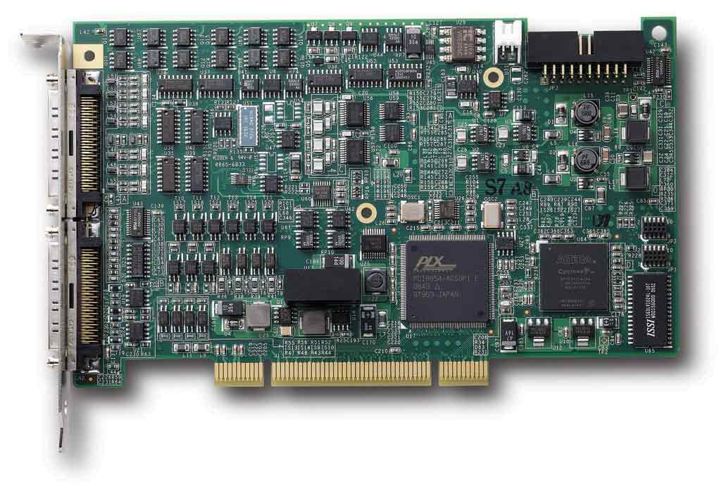
The ADLINK PCI‑9524 is a high‑precision, multifunction data acquisition and motion control card designed for industrial and laboratory applications requiring simultaneous measurement and control. It integrates 24‑bit analog‑to‑digital conversion, 16‑bit analog output, motion control for up to three axes, and isolated digital I/O in a single PCI card. The PCI‑9524 is optimized for material testing systems (MTS), precision weighing, and process automation, providing a complete hardware platform for closed‑loop control and high‑accuracy transducer measurement.
### 2. Key Features
- High‑Resolution Data Acquisition:
24‑bit A/D conversion with up to 30 kS/s sampling rate for single‑channel operation.
4 differential load‑cell transducer inputs and 4 general‑purpose analog inputs.
- Integrated Motion Control:
3‑axis stepper/servo motor control with differential pulse outputs (CW/CCW or CLK/DIR).
Built‑in incremental encoder feedback channels for closed‑loop control.
- Precision Measurement:
Supports transducer sensitivities from 1.0 mV/V to 4.0 mV/V with 1/200,000 full‑scale accuracy.
Auto‑zero and remote‑sense functions for thermal drift and line‑loss compensation.
- Analog Output:
Two 16‑bit D/A channels with ±10 V output range and 5 kS/s update rate.
- Isolated Digital I/O:
8 opto‑isolated digital inputs (0–24 V) and 8 isolated MOSFET digital outputs (up to 300 mA sink current).
- Onboard Timing Resources:
Two 32‑bit 40 MHz general‑purpose timer/counters and two 4 MHz encoder inputs.
- Connectivity:
Dual 68‑pin VHDCI (SCSI‑II) connectors for analog, digital, and motion I/O.
- Plug‑and‑Play PCI Interface:
Fully compliant with 32‑bit 3.3 V/5 V PCI bus, supporting bus‑mastering DMA and scatter/gather transfers.
- Software Support:
Compatible with ADLINK PCIS‑DASK driver library for Windows 98/NT/2000/XP/Vista and LabVIEW™.
### 3. Technical Specifications
Physical Characteristics
- Dimensions: 156 mm × 116 mm
- Weight: Approx. 200 g
- Connectors: Two 68‑pin VHDCI (SCSI‑II)
- Bus Interface: 32‑bit PCI, 3.3 V/5 V signaling
Power Requirements
- +5 V DC @ 2 A (typical)
Operating Environment
- Temperature: 0 °C – 45 °C
- Humidity: 10 % – 90 % RH, non‑condensing
Storage Environment
- Temperature: −20 °C – 80 °C
- Humidity: 5 % – 95 % RH, non‑condensing
### 4. Functionality and Applications
Functional Overview
The PCI‑9524 combines precision analog measurement and motion control in one module. It measures strain‑gauge‑based load cells, LVDTs, and potentiometric sensors while simultaneously controlling servo or stepper motors. The card’s architecture integrates A/D and D/A converters, digital filters, isolated I/O, and motion control logic under FPGA management.
Typical Applications
- Material and fatigue testing systems (MTS)
- Precision weighing and force measurement
- Automotive and mechanical testing
- Process control and automation
- Laboratory instrumentation and calibration systems
- Biomechanical and biomedical measurement setups
Compatibility
- Standard PCI slots in industrial PCs
- Supported OS: Windows 98/NT/2000/XP/Vista
- Software: ADLINK PCIS‑DASK, LabVIEW drivers, and All‑in‑One CD utilities
### 5. Components & Accessories
Included Items
- PCI‑9524 DAQ card
- User’s Manual
- Software Installation Guide
- ADLINK All‑in‑One CD (drivers, libraries, manuals)
Optional Accessories
- DIN‑68S‑01 Termination Board: 68‑pin SCSI‑II connector with DIN‑rail mounting
- Cables: Shielded VHDCI‑to‑VHDCI or VHDCI‑to‑SCSI‑II cables (sold separately)
Connectors
- CN1: Analog inputs, excitation, and analog outputs
- CN2: Digital I/O, encoder, and pulse command signals
- SSI: Synchronization interface
### 6. Installation & Setup
Requirements
- Standard PCI slot (32‑bit, 3.3 V or 5 V)
- Anti‑static handling precautions (ESD protection)
- Phillips screwdriver and anti‑static wrist strap
Installation Steps
1. Power off the host system and remove the chassis cover.
2. Insert the PCI‑9524 into an available PCI slot and secure it.
3. Replace the cover and power on the system.
4. The card is plug‑and‑play; the BIOS assigns IRQ and memory resources automatically.
5. Install drivers from the ADLINK All‑in‑One CD and verify configuration using the PCI_SCAN utility.
Configuration
- No jumpers required; all settings are software‑controlled.
- Supports bus‑mastering DMA and scatter/gather for high‑speed data transfer.
### 7. Performance & Capabilities
#### Analog Input for Load‑Cell Transducers
- Channels: 4 differential
- Resolution: 24 bits (ADS1255 A/D converter)
- Sampling Rate:
- 30 kS/s (single channel, auto‑zero disabled)
- 4 kS/s (multi‑channel)
- 800 S/s (auto‑zero enabled)
- Input Range: ±200 mV (fixed gain × 25)
- Sensitivity: 1.0 – 4.0 mV/V
- Excitation Voltage: 2.5 V DC or 10 V DC (selectable)
- Accuracy: 1/200,000 FS (with remote sense and auto‑zero)
- Input Impedance: 1 GΩ || 3 pF
- CMRR: 90 dB (auto‑zero off), 102 dB (auto‑zero on)
- FIFO Buffer: 1024 × 32‑bit samples
#### General‑Purpose Analog Input
- Channels: 4 differential
- Resolution: 24 bits
- Input Ranges: ±1.25 V, ±2.5 V, ±5 V, ±10 V (programmable)
- Sampling Rate: 30 kS/s (non‑multiplexed)
- Input Impedance: 1 GΩ || 3 pF
- CMRR: up to 98 dB
- FIFO Buffer: 1024 × 32‑bit samples
#### Analog Output
- Channels: 2
- Resolution: 16 bits (DAC8812)
- Output Range: ±10 V
- Update Rate: 5 kS/s (max)
- Output Drive: ±5 mA, 0.1 Ω output impedance
- Settling Time: 2 µs (0.1 % FS)
- Short‑circuit protection to ground
#### Motion Control
- Axes: 3 (stepper/servo)
- Output Type: Differential line driver (AM26LS31, 20 mA drive)
- Modes: OUT/DIR, CW/CCW
- Max Frequency: 500 kHz
- Encoder Inputs: 3 channels, 24‑bit up/down counters, 1 MHz max
- Decoder Type: Quadrature (×4 resolution)
- Position Comparator Trigger for synchronized acquisition
#### Isolated Digital I/O
- Inputs: 8 channels, 0–24 V, 2.7 kΩ input resistance, 5 kHz max
- Outputs: 8 channels, N‑MOSFET sink type, 60 V DC max, 300 mA/channel
- Isolation: Opto‑isolated, shared ISOGND reference
#### Isolated Power Supplies
- ISO5VDD: 5 V ± 0.05 V, 160 mA max
- ISOPWR: 5 V ± 0.15 V, 16 mA max
#### Timing & Triggering
- Internal 40 MHz time base
- Trigger Modes: Software, external digital, pulse comparator, position comparator
- Post‑trigger and re‑trigger supported
#### Data Transfer
- Programmed I/O and bus‑mastering DMA (scatter/gather supported)
- Onboard 256‑sample A/D FIFO and 1 k‑sample D/A FIFO
### 8. Standards & Compliance
- Bus Interface: PCI 2.2 compliant (32‑bit, 33 MHz)
- Electrical Standards: ANSI TIA/EIA‑422‑B, ITU V.11 differential signaling
- Environmental Compliance:
- RoHS (Restriction of Hazardous Substances)
- WEEE (Waste Electrical and Electronic Equipment)
- Safety & EMC: Designed for industrial environments with opto‑isolation and EMI protection
- Quality Assurance: Manufactured under ISO‑certified processes by ADLINK Technology Inc.
### 9. Additional Information
Calibration & Accuracy
- Factory‑calibrated with stored constants in EEPROM
- Auto‑calibration and user calibration supported
- Warm‑up time: 25 minutes (typical)
- Accuracy after calibration: ±0.001 mV offset, ±0.5 % gain error (typical)
Maintenance & Support
- Two‑year limited warranty (one year in China)
- Global technical support via ADLINK regional offices
- Software updates and documentation available at [www.adlinktech.com](http://www.adlinktech.com)
Safety & Handling
- ESD‑sensitive device; handle with grounded wrist strap
- Operate within specified environmental limits
- Follow all safety instructions in the user manual
Service Contacts
- Headquarters: ADLINK Technology Inc., Taipei, Taiwan
- Regional Offices: USA, Europe, China, Japan, Korea, Singapore, India
### Summary
The ADLINK PCI‑9524 is a high‑precision, multifunction PCI data acquisition and motion control card engineered for demanding industrial and laboratory measurement systems. Its 24‑bit A/D resolution, 16‑bit analog output, and integrated 3‑axis motion control make it a complete solution for closed‑loop control and high‑accuracy transducer measurement. With programmable excitation, auto‑zero, remote‑sense, and isolated I/O, the PCI‑9524 ensures exceptional accuracy and noise immunity. Compliance with PCI standards, RoHS/WEEE directives, and comprehensive software support make it a robust, reliable platform for precision automation and testing applications.

### 1. Product Overview
Product Name: PCI‑9524
Model: PCI‑9524
Series: PCI Multifunction Data Acquisition (DAQ) and Motion Control Series
Article Number: PCI‑9524
Manufacturer: ADLINK Technology Inc.
Manufacturer Part No.: 50‑11236‑1000
Manual Revision: 2.00 (April 9, 2008)
The ADLINK PCI‑9524 is a high‑precision, multifunction data acquisition and motion control card designed for industrial and laboratory applications requiring simultaneous measurement and control. It integrates 24‑bit analog‑to‑digital conversion, 16‑bit analog output, motion control for up to three axes, and isolated digital I/O in a single PCI card. The PCI‑9524 is optimized for material testing systems (MTS), precision weighing, and process automation, providing a complete hardware platform for closed‑loop control and high‑accuracy transducer measurement.
### 2. Key Features
- High‑Resolution Data Acquisition:
24‑bit A/D conversion with up to 30 kS/s sampling rate for single‑channel operation.
4 differential load‑cell transducer inputs and 4 general‑purpose analog inputs.
- Integrated Motion Control:
3‑axis stepper/servo motor control with differential pulse outputs (CW/CCW or CLK/DIR).
Built‑in incremental encoder feedback channels for closed‑loop control.
- Precision Measurement:
Supports transducer sensitivities from 1.0 mV/V to 4.0 mV/V with 1/200,000 full‑scale accuracy.
Auto‑zero and remote‑sense functions for thermal drift and line‑loss compensation.
- Analog Output:
Two 16‑bit D/A channels with ±10 V output range and 5 kS/s update rate.
- Isolated Digital I/O:
8 opto‑isolated digital inputs (0–24 V) and 8 isolated MOSFET digital outputs (up to 300 mA sink current).
- Onboard Timing Resources:
Two 32‑bit 40 MHz general‑purpose timer/counters and two 4 MHz encoder inputs.
- Connectivity:
Dual 68‑pin VHDCI (SCSI‑II) connectors for analog, digital, and motion I/O.
- Plug‑and‑Play PCI Interface:
Fully compliant with 32‑bit 3.3 V/5 V PCI bus, supporting bus‑mastering DMA and scatter/gather transfers.
- Software Support:
Compatible with ADLINK PCIS‑DASK driver library for Windows 98/NT/2000/XP/Vista and LabVIEW™.
### 3. Technical Specifications
Physical Characteristics
- Dimensions: 156 mm × 116 mm
- Weight: Approx. 200 g
- Connectors: Two 68‑pin VHDCI (SCSI‑II)
- Bus Interface: 32‑bit PCI, 3.3 V/5 V signaling
Power Requirements
- +5 V DC @ 2 A (typical)
Operating Environment
- Temperature: 0 °C – 45 °C
- Humidity: 10 % – 90 % RH, non‑condensing
Storage Environment
- Temperature: −20 °C – 80 °C
- Humidity: 5 % – 95 % RH, non‑condensing
### 4. Functionality and Applications
Functional Overview
The PCI‑9524 combines precision analog measurement and motion control in one module. It measures strain‑gauge‑based load cells, LVDTs, and potentiometric sensors while simultaneously controlling servo or stepper motors. The card’s architecture integrates A/D and D/A converters, digital filters, isolated I/O, and motion control logic under FPGA management.
Typical Applications
- Material and fatigue testing systems (MTS)
- Precision weighing and force measurement
- Automotive and mechanical testing
- Process control and automation
- Laboratory instrumentation and calibration systems
- Biomechanical and biomedical measurement setups
Compatibility
- Standard PCI slots in industrial PCs
- Supported OS: Windows 98/NT/2000/XP/Vista
- Software: ADLINK PCIS‑DASK, LabVIEW drivers, and All‑in‑One CD utilities
### 5. Components & Accessories
Included Items
- PCI‑9524 DAQ card
- User’s Manual
- Software Installation Guide
- ADLINK All‑in‑One CD (drivers, libraries, manuals)
Optional Accessories
- DIN‑68S‑01 Termination Board: 68‑pin SCSI‑II connector with DIN‑rail mounting
- Cables: Shielded VHDCI‑to‑VHDCI or VHDCI‑to‑SCSI‑II cables (sold separately)
Connectors
- CN1: Analog inputs, excitation, and analog outputs
- CN2: Digital I/O, encoder, and pulse command signals
- SSI: Synchronization interface
### 6. Installation & Setup
Requirements
- Standard PCI slot (32‑bit, 3.3 V or 5 V)
- Anti‑static handling precautions (ESD protection)
- Phillips screwdriver and anti‑static wrist strap
Installation Steps
1. Power off the host system and remove the chassis cover.
2. Insert the PCI‑9524 into an available PCI slot and secure it.
3. Replace the cover and power on the system.
4. The card is plug‑and‑play; the BIOS assigns IRQ and memory resources automatically.
5. Install drivers from the ADLINK All‑in‑One CD and verify configuration using the PCI_SCAN utility.
Configuration
- No jumpers required; all settings are software‑controlled.
- Supports bus‑mastering DMA and scatter/gather for high‑speed data transfer.
### 7. Performance & Capabilities
#### Analog Input for Load‑Cell Transducers
- Channels: 4 differential
- Resolution: 24 bits (ADS1255 A/D converter)
- Sampling Rate:
- 30 kS/s (single channel, auto‑zero disabled)
- 4 kS/s (multi‑channel)
- 800 S/s (auto‑zero enabled)
- Input Range: ±200 mV (fixed gain × 25)
- Sensitivity: 1.0 – 4.0 mV/V
- Excitation Voltage: 2.5 V DC or 10 V DC (selectable)
- Accuracy: 1/200,000 FS (with remote sense and auto‑zero)
- Input Impedance: 1 GΩ || 3 pF
- CMRR: 90 dB (auto‑zero off), 102 dB (auto‑zero on)
- FIFO Buffer: 1024 × 32‑bit samples
#### General‑Purpose Analog Input
- Channels: 4 differential
- Resolution: 24 bits
- Input Ranges: ±1.25 V, ±2.5 V, ±5 V, ±10 V (programmable)
- Sampling Rate: 30 kS/s (non‑multiplexed)
- Input Impedance: 1 GΩ || 3 pF
- CMRR: up to 98 dB
- FIFO Buffer: 1024 × 32‑bit samples
#### Analog Output
- Channels: 2
- Resolution: 16 bits (DAC8812)
- Output Range: ±10 V
- Update Rate: 5 kS/s (max)
- Output Drive: ±5 mA, 0.1 Ω output impedance
- Settling Time: 2 µs (0.1 % FS)
- Short‑circuit protection to ground
#### Motion Control
- Axes: 3 (stepper/servo)
- Output Type: Differential line driver (AM26LS31, 20 mA drive)
- Modes: OUT/DIR, CW/CCW
- Max Frequency: 500 kHz
- Encoder Inputs: 3 channels, 24‑bit up/down counters, 1 MHz max
- Decoder Type: Quadrature (×4 resolution)
- Position Comparator Trigger for synchronized acquisition
#### Isolated Digital I/O
- Inputs: 8 channels, 0–24 V, 2.7 kΩ input resistance, 5 kHz max
- Outputs: 8 channels, N‑MOSFET sink type, 60 V DC max, 300 mA/channel
- Isolation: Opto‑isolated, shared ISOGND reference
#### Isolated Power Supplies
- ISO5VDD: 5 V ± 0.05 V, 160 mA max
- ISOPWR: 5 V ± 0.15 V, 16 mA max
#### Timing & Triggering
- Internal 40 MHz time base
- Trigger Modes: Software, external digital, pulse comparator, position comparator
- Post‑trigger and re‑trigger supported
#### Data Transfer
- Programmed I/O and bus‑mastering DMA (scatter/gather supported)
- Onboard 256‑sample A/D FIFO and 1 k‑sample D/A FIFO
### 8. Standards & Compliance
- Bus Interface: PCI 2.2 compliant (32‑bit, 33 MHz)
- Electrical Standards: ANSI TIA/EIA‑422‑B, ITU V.11 differential signaling
- Environmental Compliance:
- RoHS (Restriction of Hazardous Substances)
- WEEE (Waste Electrical and Electronic Equipment)
- Safety & EMC: Designed for industrial environments with opto‑isolation and EMI protection
- Quality Assurance: Manufactured under ISO‑certified processes by ADLINK Technology Inc.
### 9. Additional Information
Calibration & Accuracy
- Factory‑calibrated with stored constants in EEPROM
- Auto‑calibration and user calibration supported
- Warm‑up time: 25 minutes (typical)
- Accuracy after calibration: ±0.001 mV offset, ±0.5 % gain error (typical)
Maintenance & Support
- Two‑year limited warranty (one year in China)
- Global technical support via ADLINK regional offices
- Software updates and documentation available at [www.adlinktech.com](http://www.adlinktech.com)
Safety & Handling
- ESD‑sensitive device; handle with grounded wrist strap
- Operate within specified environmental limits
- Follow all safety instructions in the user manual
Service Contacts
- Headquarters: ADLINK Technology Inc., Taipei, Taiwan
- Regional Offices: USA, Europe, China, Japan, Korea, Singapore, India
### Summary
The ADLINK PCI‑9524 is a high‑precision, multifunction PCI data acquisition and motion control card engineered for demanding industrial and laboratory measurement systems. Its 24‑bit A/D resolution, 16‑bit analog output, and integrated 3‑axis motion control make it a complete solution for closed‑loop control and high‑accuracy transducer measurement. With programmable excitation, auto‑zero, remote‑sense, and isolated I/O, the PCI‑9524 ensures exceptional accuracy and noise immunity. Compliance with PCI standards, RoHS/WEEE directives, and comprehensive software support make it a robust, reliable platform for precision automation and testing applications.
-
PCI-9524_Datasheet_1.pdf
PDF Catalog
-
PCI-9524.pdf
Manual
- DIN-68S-01 - 68pin SCSI-II termination board DIN rail w/o cable
- ACL-10568-1 - SCSI-VHDCI cable 1m for DAQ series
- ACL-10568-2 - SCSI-VHDCI cable 2m for DAQ series
- ACL-10568-3 - SCSI-VHDCI cable 3m for DAQ series