LOOKING FOR THE RIGHT
INDUSTRIAL SOLUTION?
Discover embedded, communication and automation solutions tailored to your application.
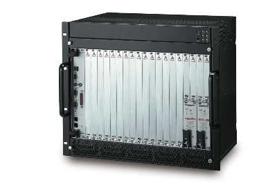
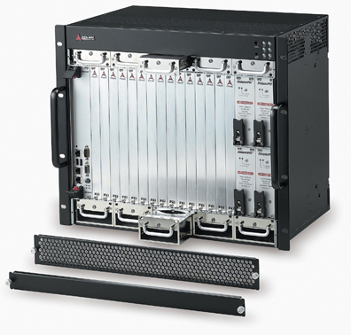
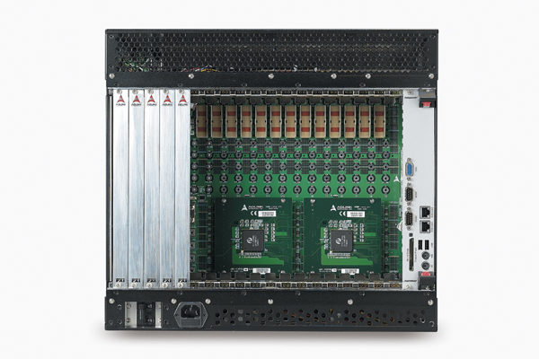
- PXI and CompactPCI Compatibility: Supports 6U PXI and CompactPCI modules, ensuring flexibility across instrumentation and industrial control applications.
- PXI Specification Rev. 2.2 Compliance: Guarantees interoperability with PXI‑compliant modules and controllers.
- 15‑Slot Architecture: One system slot and fourteen peripheral slots for extensive module integration.
- Dual Hot‑Swappable Power Supplies: Two 250 W CompactPCI power modules with universal 100–240 VAC input; optional 1000 W configuration for power‑intensive systems.
- Advanced Cooling System: Ten dual‑ball‑bearing fans (five intake, five exhaust) delivering a combined 482 CFM airflow for superior thermal stability.
- System Monitoring and Alarms: Front‑panel LEDs and buzzer alarms for voltage, temperature, and fan status; includes alarm reset button.
- Magnetic Circuit Breaker Protection: Provides AC input protection and easy reset capability.
- Star Trigger and Trigger Bus Support: Enables precise synchronization among multiple PXI modules with <1 ns skew.
- 10 MHz Reference Clock Distribution: Buffered, low‑skew clock signal available to all peripheral slots for timing synchronization.
- Filtered, Forced‑Air Cooling Architecture: Ensures clean airflow and extended component life.
- Optional Trigger Bus Connectivity (TB Models): Configurable trigger bus segments for flexible signal routing.
- Rackmountable 19‑inch Form Factor: Suitable for laboratory, production, and field environments.
- PXI Specification Rev. 2.2 Compliance: Guarantees interoperability with PXI‑compliant modules and controllers.
- 15‑Slot Architecture: One system slot and fourteen peripheral slots for extensive module integration.
- Dual Hot‑Swappable Power Supplies: Two 250 W CompactPCI power modules with universal 100–240 VAC input; optional 1000 W configuration for power‑intensive systems.
- Advanced Cooling System: Ten dual‑ball‑bearing fans (five intake, five exhaust) delivering a combined 482 CFM airflow for superior thermal stability.
- System Monitoring and Alarms: Front‑panel LEDs and buzzer alarms for voltage, temperature, and fan status; includes alarm reset button.
- Magnetic Circuit Breaker Protection: Provides AC input protection and easy reset capability.
- Star Trigger and Trigger Bus Support: Enables precise synchronization among multiple PXI modules with <1 ns skew.
- 10 MHz Reference Clock Distribution: Buffered, low‑skew clock signal available to all peripheral slots for timing synchronization.
- Filtered, Forced‑Air Cooling Architecture: Ensures clean airflow and extended component life.
- Optional Trigger Bus Connectivity (TB Models): Configurable trigger bus segments for flexible signal routing.
- Rackmountable 19‑inch Form Factor: Suitable for laboratory, production, and field environments.
Comprehensive Product Summary: ADLINK PXIS‑3320 15‑Slot 6U PXI/CompactPCI Chassis
### 1. Product Overview
Product Name: PXIS‑3320
Model: PXIS‑3320 / PXIS‑3320/1000W / PXIS‑3320/TB / PXIS‑3320/1000W/TB
Series: PXIS‑33xx PXI/CompactPCI Chassis Series
Article Number: PXIS‑3320
Manufacturer: ADLINK Technology Inc.
Manufacturer Address: 9F, No. 166, Jian Yi Road, Chungho City, Taipei 235, Taiwan
Website: [www.adlinktech.com](http://www.adlinktech.com)
The ADLINK PXIS‑3320 is a 19‑inch, 6U PXI/CompactPCI chassis designed for high‑performance test, measurement, and automation applications. It accommodates one system controller slot and fourteen peripheral slots, supporting both PXI and CompactPCI 6U modules. The chassis integrates dual hot‑swappable 250 W CompactPCI power supply modules (500 W total) with optional 1000 W configuration, advanced thermal management, and comprehensive system monitoring. Fully compliant with PXI Specification Rev. 2.2 and PICMG 2.11 standards, the PXIS‑3320 provides a robust, scalable platform for modular instrumentation systems.
### 2. Key Features
- PXI and CompactPCI Compatibility: Supports 6U PXI and CompactPCI modules, ensuring flexibility across instrumentation and industrial control applications.
- PXI Specification Rev. 2.2 Compliance: Guarantees interoperability with PXI‑compliant modules and controllers.
- 15‑Slot Architecture: One system slot and fourteen peripheral slots for extensive module integration.
- Dual Hot‑Swappable Power Supplies: Two 250 W CompactPCI power modules with universal 100–240 VAC input; optional 1000 W configuration for power‑intensive systems.
- Advanced Cooling System: Ten dual‑ball‑bearing fans (five intake, five exhaust) delivering a combined 482 CFM airflow for superior thermal stability.
- System Monitoring and Alarms: Front‑panel LEDs and buzzer alarms for voltage, temperature, and fan status; includes alarm reset button.
- Magnetic Circuit Breaker Protection: Provides AC input protection and easy reset capability.
- Star Trigger and Trigger Bus Support: Enables precise synchronization among multiple PXI modules with <1 ns skew.
- 10 MHz Reference Clock Distribution: Buffered, low‑skew clock signal available to all peripheral slots for timing synchronization.
- Filtered, Forced‑Air Cooling Architecture: Ensures clean airflow and extended component life.
- Optional Trigger Bus Connectivity (TB Models): Configurable trigger bus segments for flexible signal routing.
- Rackmountable 19‑inch Form Factor: Suitable for laboratory, production, and field environments.
### 3. Technical Specifications
Slots:
- 15 total (1 system slot + 14 peripheral slots)
- Star trigger slot: Slot 2
- PXI trigger bus and local bus per PXI 2.2
Dimensions:
- 483 mm (W) × 398 mm (H) × 295 mm (D) (18.8 × 15.5 × 11.5 in), without handles
Weight:
- 23 kg (50.6 lb)
Power Supply:
- Form Factor: PICMG 2.11‑compliant CompactPCI power module
- Input Voltage: 100–240 VAC, 47–63 Hz
- Output Power: 250 W per module (500 W total standard; 1000 W optional)
- DC Output Rails:
- +5 V @ 25 A typ / 33 A max
- +3.3 V @ 18 A typ / 33 A max
- +12 V @ 5 A typ / 5.5 A max
- −12 V @ 0.5 A typ / 1 A max
Cooling System:
- Ten 80 × 80 × 25 mm dual‑ball‑bearing fans (12 VDC, 2.64 W each)
- Five intake fans (bottom) + five exhaust fans (top)
- Airflow: 241 CFM intake + 241 CFM exhaust (total ≈ 482 CFM)
- Rated Speed: 4000–5000 RPM
- Hot‑swappable fan trays
Environmental Conditions:
- Operating Temperature: 0 °C to 45 °C (32 °F to 113 °F)
- Storage Temperature: −20 °C to 70 °C (−4 °F to 158 °F)
- Operating Humidity: 10 % to 90 %, non‑condensing
- Storage Humidity: 5 % to 95 %, non‑condensing
Shock and Vibration:
- Shock: 15 G peak‑to‑peak, 11 ms duration
- Random Vibration: 5–500 Hz, 0.5 G RMS (operating); 1.88 G RMS (non‑operating)
Material and Construction:
- Backplane: UL 94V‑0 rated PCB
- Connectors: IEC‑917 and IEC 10764‑101 compliant
- Chassis: Industrial‑grade steel with front handles and removable fan trays
### 4. Functionality
The PXIS‑3320 serves as a modular platform for PXI and CompactPCI instrumentation systems. It provides a unified backplane with integrated timing, triggering, and communication buses to interconnect measurement, control, and data‑acquisition modules.
Operation and Architecture:
- System Slot (Slot 1): Hosts a PXI or CompactPCI system controller (e.g., ADLINK cPCI‑6840 or cPCI‑6860A).
- Star Trigger Slot (Slot 2): Provides dedicated trigger lines to slots 3–15 with <1 ns skew for precise synchronization.
- Peripheral Slots (Slots 3–15): Accept 6U PXI/CompactPCI peripheral modules for signal acquisition, generation, or control.
- Local Bus: 14‑line daisy‑chained bus connecting adjacent slots for high‑speed sideband communication.
- Trigger Bus: 8‑line bus for inter‑module synchronization and event triggering.
- 10 MHz Reference Clock: Distributed to all peripheral slots via matched‑impedance buffer (<1 ns skew).
Use Cases and Applications:
- Automated test equipment (ATE)
- Data acquisition and signal analysis
- Industrial process control
- Communication and RF testing
- Embedded system prototyping
- Multi‑channel synchronized measurement systems
Compatibility:
- PXI Rev. 2.2 and CompactPCI PICMG 2.0 compliant
- Compatible with ADLINK system controllers and PCI‑to‑PXI extension modules (e.g., PCI‑8570, PXI‑8570/6U)
### 5. Components & Accessories
Included Items:
- PXIS‑3320 chassis with two cPS‑H325/AC power supply modules (500 W total)
- Power cord
- User’s manual
PXIS‑3320/1000W Package:
- Chassis with four cPS‑H325/AC power supply modules (1000 W total)
- Power cord
- User’s manual
Optional Add‑Ons:
- Additional or replacement CompactPCI power modules
- Replacement fan trays
- Trigger bus connectivity (TB models)
- Recommended controllers: cPCI‑6840, cPCI‑6860A, cPCI‑6965
Connectors and Interfaces:
- AC power inlet with magnetic circuit breaker
- Front‑panel LEDs and alarm reset button
- SMB (System Management Bus) connector for monitoring
- ATX‑like DC power input connectors (CN1, CN7–CN9)
- PCI VIO selection screw terminals (+3.3 V / +5 V)
- JP1 10 MHz reference clock selector (internal/external)
- J6 INH#, J8 RST#, J9 FAL# signal connectors
- J5 LED power status connector
### 6. Installation & Setup
Requirements:
- Stable, flat surface or 19‑inch rackmount environment
- Adequate ventilation clearance above and below chassis
- Properly grounded AC power source (100–240 VAC)
Installation Steps:
1. Ensure sufficient airflow and stable placement.
2. Set power switch to OFF; connect AC power cord to grounded outlet.
3. Install system controller module in Slot 1 (align with card guides, secure with screws).
4. Install additional PXI/CompactPCI peripheral modules as required.
5. Power ON using front‑panel switch; verify LED indicators and fan operation.
Monitoring and Alarms:
- LED Indicators:
- Power (Green): ON = power supplied; OFF = no power.
- Temperature (Red): ON = < 50 °C; Flashing = > 50 °C.
- Fan (Amber): ON = normal speed; Flashing = fan failure.
- Buzzer Alarm: Sounds on power, temperature, or fan fault; reset via front‑panel button.
Grounding:
- Backplane mounting holes labeled GND (signal ground) and FGND (frame ground).
- Default configuration isolates signal and frame grounds; can be shorted externally if required.
Hot‑Swap Maintenance:
- Power modules and fan trays are hot‑swappable.
- Replace defective units by releasing handles, removing modules, and inserting replacements.
### 7. Performance & Capabilities
Electrical Performance:
- Stable multi‑rail DC output with current‑sharing redundancy.
- Supports high‑power PXI modules such as digitizers, RF analyzers, and digital I/O cards.
- Optional 1000 W configuration for extended power headroom.
Thermal Performance:
- 482 CFM total airflow ensures uniform temperature distribution.
- Front‑accessible fan trays minimize downtime (low MTTR).
- Temperature monitoring and automatic alarms prevent overheating.
Mechanical Performance:
- Rigid 6U chassis structure for vibration resistance.
- Shock tolerance up to 15 G (non‑operating).
- Designed for continuous operation in industrial environments.
Limitations:
- Operating temperature limited to 0–45 °C; requires controlled environment.
- Trigger bus segmentation varies by model (TB vs. non‑TB).
### 8. Standards & Compliance
PXI Compliance:
- PXI Specification Rev. 2.2
- Supports PXI trigger bus, star trigger, local bus, and 10 MHz reference clock
CompactPCI Compliance:
- PICMG 2.0 (CompactPCI)
- PICMG 2.11 (Power Interface)
Safety and EMC/EMI:
- CE (EN 55024 Immunity)
- EN 55022 Emissions
- FCC Class A Compliance
Backplane Materials:
- UL 94V‑0 rated PCB and connectors
Environmental and Reliability Standards:
- Designed for industrial environments with high vibration and temperature tolerance
- Meets standard shock and vibration test profiles for instrumentation chassis
### 9. Additional Information
Warranty:
- Standard 2‑year limited warranty (1 year in China)
- Covers manufacturing defects; excludes damage from misuse, environmental factors, or unauthorized repair
- RMA service available via [http://rma.adlinktech.com/policy/home.htm](http://rma.adlinktech.com/policy/home.htm)
Support and Service:
- Email: service@adlinktech.com
- Tel: +886‑2‑82265877 | Fax: +886‑2‑82265717
- Customer satisfaction and technical assistance prioritized
Maintenance:
- Regular cleaning recommended:
- Interior: Low‑velocity air or 75 % isopropyl alcohol solution (power off).
- Exterior: Lint‑free cloth with mild soap solution; avoid abrasives.
- Replace fans or power modules as needed; monitor LED and buzzer alerts.
Safety Precautions:
- Operate within 0–50 °C ambient temperature.
- Use only grounded AC outlets.
- Avoid moisture, dust, and conductive debris.
- Disconnect power before servicing.
- Lithium battery caution: risk of explosion if replaced incorrectly.
Revision and Documentation:
- User’s Manual Rev. 2.00 (October 27, 2006)
- Part No. 50‑17024‑1000
- Specifications subject to change without notice (latest update September 23, 2014).
### Summary
The ADLINK PXIS‑3320 is a high‑reliability, 15‑slot, 6U PXI/CompactPCI chassis engineered for demanding test and measurement environments. Its dual hot‑swappable power supplies, robust forced‑air cooling, and comprehensive system monitoring ensure continuous, stable operation. Full PXI 2.2 and CompactPCI compliance guarantees compatibility with a wide range of modular instruments. With optional 1000 W power capability, star trigger synchronization, and configurable trigger bus segments, the PXIS‑3320 provides a scalable foundation for complex, multi‑module test systems in industrial, research, and production settings.
### 1. Product Overview
Product Name: PXIS‑3320
Model: PXIS‑3320 / PXIS‑3320/1000W / PXIS‑3320/TB / PXIS‑3320/1000W/TB
Series: PXIS‑33xx PXI/CompactPCI Chassis Series
Article Number: PXIS‑3320
Manufacturer: ADLINK Technology Inc.
Manufacturer Address: 9F, No. 166, Jian Yi Road, Chungho City, Taipei 235, Taiwan
Website: [www.adlinktech.com](http://www.adlinktech.com)
The ADLINK PXIS‑3320 is a 19‑inch, 6U PXI/CompactPCI chassis designed for high‑performance test, measurement, and automation applications. It accommodates one system controller slot and fourteen peripheral slots, supporting both PXI and CompactPCI 6U modules. The chassis integrates dual hot‑swappable 250 W CompactPCI power supply modules (500 W total) with optional 1000 W configuration, advanced thermal management, and comprehensive system monitoring. Fully compliant with PXI Specification Rev. 2.2 and PICMG 2.11 standards, the PXIS‑3320 provides a robust, scalable platform for modular instrumentation systems.
### 2. Key Features
- PXI and CompactPCI Compatibility: Supports 6U PXI and CompactPCI modules, ensuring flexibility across instrumentation and industrial control applications.
- PXI Specification Rev. 2.2 Compliance: Guarantees interoperability with PXI‑compliant modules and controllers.
- 15‑Slot Architecture: One system slot and fourteen peripheral slots for extensive module integration.
- Dual Hot‑Swappable Power Supplies: Two 250 W CompactPCI power modules with universal 100–240 VAC input; optional 1000 W configuration for power‑intensive systems.
- Advanced Cooling System: Ten dual‑ball‑bearing fans (five intake, five exhaust) delivering a combined 482 CFM airflow for superior thermal stability.
- System Monitoring and Alarms: Front‑panel LEDs and buzzer alarms for voltage, temperature, and fan status; includes alarm reset button.
- Magnetic Circuit Breaker Protection: Provides AC input protection and easy reset capability.
- Star Trigger and Trigger Bus Support: Enables precise synchronization among multiple PXI modules with <1 ns skew.
- 10 MHz Reference Clock Distribution: Buffered, low‑skew clock signal available to all peripheral slots for timing synchronization.
- Filtered, Forced‑Air Cooling Architecture: Ensures clean airflow and extended component life.
- Optional Trigger Bus Connectivity (TB Models): Configurable trigger bus segments for flexible signal routing.
- Rackmountable 19‑inch Form Factor: Suitable for laboratory, production, and field environments.
### 3. Technical Specifications
Slots:
- 15 total (1 system slot + 14 peripheral slots)
- Star trigger slot: Slot 2
- PXI trigger bus and local bus per PXI 2.2
Dimensions:
- 483 mm (W) × 398 mm (H) × 295 mm (D) (18.8 × 15.5 × 11.5 in), without handles
Weight:
- 23 kg (50.6 lb)
Power Supply:
- Form Factor: PICMG 2.11‑compliant CompactPCI power module
- Input Voltage: 100–240 VAC, 47–63 Hz
- Output Power: 250 W per module (500 W total standard; 1000 W optional)
- DC Output Rails:
- +5 V @ 25 A typ / 33 A max
- +3.3 V @ 18 A typ / 33 A max
- +12 V @ 5 A typ / 5.5 A max
- −12 V @ 0.5 A typ / 1 A max
Cooling System:
- Ten 80 × 80 × 25 mm dual‑ball‑bearing fans (12 VDC, 2.64 W each)
- Five intake fans (bottom) + five exhaust fans (top)
- Airflow: 241 CFM intake + 241 CFM exhaust (total ≈ 482 CFM)
- Rated Speed: 4000–5000 RPM
- Hot‑swappable fan trays
Environmental Conditions:
- Operating Temperature: 0 °C to 45 °C (32 °F to 113 °F)
- Storage Temperature: −20 °C to 70 °C (−4 °F to 158 °F)
- Operating Humidity: 10 % to 90 %, non‑condensing
- Storage Humidity: 5 % to 95 %, non‑condensing
Shock and Vibration:
- Shock: 15 G peak‑to‑peak, 11 ms duration
- Random Vibration: 5–500 Hz, 0.5 G RMS (operating); 1.88 G RMS (non‑operating)
Material and Construction:
- Backplane: UL 94V‑0 rated PCB
- Connectors: IEC‑917 and IEC 10764‑101 compliant
- Chassis: Industrial‑grade steel with front handles and removable fan trays
### 4. Functionality
The PXIS‑3320 serves as a modular platform for PXI and CompactPCI instrumentation systems. It provides a unified backplane with integrated timing, triggering, and communication buses to interconnect measurement, control, and data‑acquisition modules.
Operation and Architecture:
- System Slot (Slot 1): Hosts a PXI or CompactPCI system controller (e.g., ADLINK cPCI‑6840 or cPCI‑6860A).
- Star Trigger Slot (Slot 2): Provides dedicated trigger lines to slots 3–15 with <1 ns skew for precise synchronization.
- Peripheral Slots (Slots 3–15): Accept 6U PXI/CompactPCI peripheral modules for signal acquisition, generation, or control.
- Local Bus: 14‑line daisy‑chained bus connecting adjacent slots for high‑speed sideband communication.
- Trigger Bus: 8‑line bus for inter‑module synchronization and event triggering.
- 10 MHz Reference Clock: Distributed to all peripheral slots via matched‑impedance buffer (<1 ns skew).
Use Cases and Applications:
- Automated test equipment (ATE)
- Data acquisition and signal analysis
- Industrial process control
- Communication and RF testing
- Embedded system prototyping
- Multi‑channel synchronized measurement systems
Compatibility:
- PXI Rev. 2.2 and CompactPCI PICMG 2.0 compliant
- Compatible with ADLINK system controllers and PCI‑to‑PXI extension modules (e.g., PCI‑8570, PXI‑8570/6U)
### 5. Components & Accessories
Included Items:
- PXIS‑3320 chassis with two cPS‑H325/AC power supply modules (500 W total)
- Power cord
- User’s manual
PXIS‑3320/1000W Package:
- Chassis with four cPS‑H325/AC power supply modules (1000 W total)
- Power cord
- User’s manual
Optional Add‑Ons:
- Additional or replacement CompactPCI power modules
- Replacement fan trays
- Trigger bus connectivity (TB models)
- Recommended controllers: cPCI‑6840, cPCI‑6860A, cPCI‑6965
Connectors and Interfaces:
- AC power inlet with magnetic circuit breaker
- Front‑panel LEDs and alarm reset button
- SMB (System Management Bus) connector for monitoring
- ATX‑like DC power input connectors (CN1, CN7–CN9)
- PCI VIO selection screw terminals (+3.3 V / +5 V)
- JP1 10 MHz reference clock selector (internal/external)
- J6 INH#, J8 RST#, J9 FAL# signal connectors
- J5 LED power status connector
### 6. Installation & Setup
Requirements:
- Stable, flat surface or 19‑inch rackmount environment
- Adequate ventilation clearance above and below chassis
- Properly grounded AC power source (100–240 VAC)
Installation Steps:
1. Ensure sufficient airflow and stable placement.
2. Set power switch to OFF; connect AC power cord to grounded outlet.
3. Install system controller module in Slot 1 (align with card guides, secure with screws).
4. Install additional PXI/CompactPCI peripheral modules as required.
5. Power ON using front‑panel switch; verify LED indicators and fan operation.
Monitoring and Alarms:
- LED Indicators:
- Power (Green): ON = power supplied; OFF = no power.
- Temperature (Red): ON = < 50 °C; Flashing = > 50 °C.
- Fan (Amber): ON = normal speed; Flashing = fan failure.
- Buzzer Alarm: Sounds on power, temperature, or fan fault; reset via front‑panel button.
Grounding:
- Backplane mounting holes labeled GND (signal ground) and FGND (frame ground).
- Default configuration isolates signal and frame grounds; can be shorted externally if required.
Hot‑Swap Maintenance:
- Power modules and fan trays are hot‑swappable.
- Replace defective units by releasing handles, removing modules, and inserting replacements.
### 7. Performance & Capabilities
Electrical Performance:
- Stable multi‑rail DC output with current‑sharing redundancy.
- Supports high‑power PXI modules such as digitizers, RF analyzers, and digital I/O cards.
- Optional 1000 W configuration for extended power headroom.
Thermal Performance:
- 482 CFM total airflow ensures uniform temperature distribution.
- Front‑accessible fan trays minimize downtime (low MTTR).
- Temperature monitoring and automatic alarms prevent overheating.
Mechanical Performance:
- Rigid 6U chassis structure for vibration resistance.
- Shock tolerance up to 15 G (non‑operating).
- Designed for continuous operation in industrial environments.
Limitations:
- Operating temperature limited to 0–45 °C; requires controlled environment.
- Trigger bus segmentation varies by model (TB vs. non‑TB).
### 8. Standards & Compliance
PXI Compliance:
- PXI Specification Rev. 2.2
- Supports PXI trigger bus, star trigger, local bus, and 10 MHz reference clock
CompactPCI Compliance:
- PICMG 2.0 (CompactPCI)
- PICMG 2.11 (Power Interface)
Safety and EMC/EMI:
- CE (EN 55024 Immunity)
- EN 55022 Emissions
- FCC Class A Compliance
Backplane Materials:
- UL 94V‑0 rated PCB and connectors
Environmental and Reliability Standards:
- Designed for industrial environments with high vibration and temperature tolerance
- Meets standard shock and vibration test profiles for instrumentation chassis
### 9. Additional Information
Warranty:
- Standard 2‑year limited warranty (1 year in China)
- Covers manufacturing defects; excludes damage from misuse, environmental factors, or unauthorized repair
- RMA service available via [http://rma.adlinktech.com/policy/home.htm](http://rma.adlinktech.com/policy/home.htm)
Support and Service:
- Email: service@adlinktech.com
- Tel: +886‑2‑82265877 | Fax: +886‑2‑82265717
- Customer satisfaction and technical assistance prioritized
Maintenance:
- Regular cleaning recommended:
- Interior: Low‑velocity air or 75 % isopropyl alcohol solution (power off).
- Exterior: Lint‑free cloth with mild soap solution; avoid abrasives.
- Replace fans or power modules as needed; monitor LED and buzzer alerts.
Safety Precautions:
- Operate within 0–50 °C ambient temperature.
- Use only grounded AC outlets.
- Avoid moisture, dust, and conductive debris.
- Disconnect power before servicing.
- Lithium battery caution: risk of explosion if replaced incorrectly.
Revision and Documentation:
- User’s Manual Rev. 2.00 (October 27, 2006)
- Part No. 50‑17024‑1000
- Specifications subject to change without notice (latest update September 23, 2014).
### Summary
The ADLINK PXIS‑3320 is a high‑reliability, 15‑slot, 6U PXI/CompactPCI chassis engineered for demanding test and measurement environments. Its dual hot‑swappable power supplies, robust forced‑air cooling, and comprehensive system monitoring ensure continuous, stable operation. Full PXI 2.2 and CompactPCI compliance guarantees compatibility with a wide range of modular instruments. With optional 1000 W power capability, star trigger synchronization, and configurable trigger bus segments, the PXIS‑3320 provides a scalable foundation for complex, multi‑module test systems in industrial, research, and production settings.
-
 PXIS-3320_Datasheet_en_1.pdf
PDF Catalog
PXIS-3320_Datasheet_en_1.pdf
PDF Catalog
-
 PXIS-3320_Manual_5.pdf
Manual
PXIS-3320_Manual_5.pdf
Manual
No accessories available.