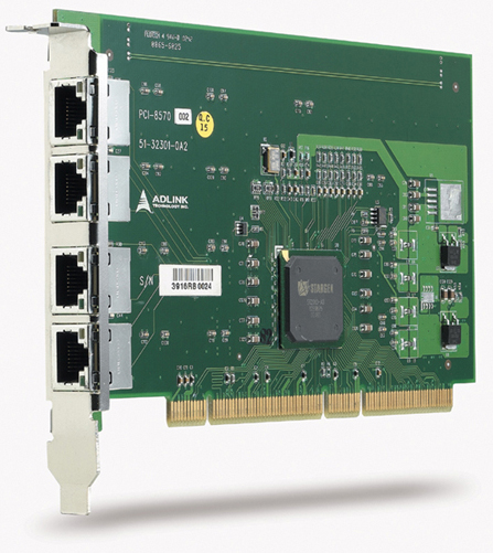
- Purpose‑built for PCI/PXI Extension: Designed specifically for use with ADLINK PCI‑8570 and PXI‑8570 modules, as well as PCIS‑8580‑series PCI‑to‑PCI extension systems.
- High‑speed Serial Transmission: Supports StarFabric serial interconnect technology with 622 Mbps LVDS differential signaling per pair, achieving up to 2.5 Gbps full‑duplex link bandwidth (5 Gbps aggregate).
- Shielded Twisted‑Pair Construction: Eight pairs of individually shielded twisted copper wires minimize crosstalk and EMI, ensuring signal integrity over extended distances.
- Robust Connectivity: Equipped with a 24‑pin DVI‑D connector for secure, high‑density signal interfacing between host and extension chassis.
- Full PCI Bandwidth Support: Maintains complete 32‑bit/33 MHz PCI bandwidth (132 MB/s) without degradation.
- Hardware and Software Transparency: Operates as a transparent physical link—no drivers or software configuration required.
- Flexible Length Options: Available in 2 m (ACL‑PXIES‑2), 5 m (ACL‑PXIES‑5), and 10 m (ACL‑PXIES‑10) variants.
- Industrial‑grade Reliability: Designed for continuous operation in 0 °C – 50 °C environments with high humidity tolerance.
- Compatibility: Fully compatible with ADLINK’s PCI‑to‑PXI and PXI‑to‑PXI extension architectures, including multi‑chassis configurations.
Comprehensive Product Summary: ADLINK ACL‑PXIES‑2 PXI‑to‑PCI Extension Cable
### 1. Product Overview
Product Name: PXI to PCI Extension Cable
Model: ACL‑PXIES‑2
Series: PXI/PCI Extension Accessories
Article Number: ACL‑PXIES‑2
Manufacturer: ADLINK Technology Inc.
Product Type: Shielded copper interconnect cable for PCI‑to‑PXI or PXI‑to‑PXI bridge systems
Associated Systems: PCI‑8570 / PXI‑8570 Extension Modules, PCIS‑8580‑4S, PCIS‑8580‑13S PCI‑to‑PCI Extension Systems
The ADLINK ACL‑PXIES‑2 is a high‑performance, shielded copper cable designed to interconnect PCI and PXI extension modules within ADLINK’s StarFabric‑based bus extension architecture. It provides a robust, low‑latency, high‑integrity data link between host and remote chassis, enabling transparent PCI bus extension up to 10 m. The 2 m version (ACL‑PXIES‑2) is optimized for short‑distance, high‑reliability installations in industrial, test, and embedded computing environments.
### 2. Key Features
- Purpose‑built for PCI/PXI Extension: Designed specifically for use with ADLINK PCI‑8570 and PXI‑8570 modules, as well as PCIS‑8580‑series PCI‑to‑PCI extension systems.
- High‑speed Serial Transmission: Supports StarFabric serial interconnect technology with 622 Mbps LVDS differential signaling per pair, achieving up to 2.5 Gbps full‑duplex link bandwidth (5 Gbps aggregate).
- Shielded Twisted‑Pair Construction: Eight pairs of individually shielded twisted copper wires minimize crosstalk and EMI, ensuring signal integrity over extended distances.
- Robust Connectivity: Equipped with a 24‑pin DVI‑D connector for secure, high‑density signal interfacing between host and extension chassis.
- Full PCI Bandwidth Support: Maintains complete 32‑bit/33 MHz PCI bandwidth (132 MB/s) without degradation.
- Hardware and Software Transparency: Operates as a transparent physical link—no drivers or software configuration required.
- Flexible Length Options: Available in 2 m (ACL‑PXIES‑2), 5 m (ACL‑PXIES‑5), and 10 m (ACL‑PXIES‑10) variants.
- Industrial‑grade Reliability: Designed for continuous operation in 0 °C – 50 °C environments with high humidity tolerance.
- Compatibility: Fully compatible with ADLINK’s PCI‑to‑PXI and PXI‑to‑PXI extension architectures, including multi‑chassis configurations.
### 3. Technical Specifications
Cable Type: Shielded twisted‑pair copper cable
Length: 2 m
Conductor Configuration: 8 pairs of shielded twisted copper wires
Connector Type: DVI‑D 24‑pin male connector (both ends)
Signal Type: Low Voltage Differential Signaling (LVDS)
Transmission Rate: 622 Mbps per pair (2.5 Gbps full‑duplex total)
Supported Bus Bandwidth: 132 MB/s (32‑bit/33 MHz PCI)
Maximum Extension Distance (System): 10 m (using ACL‑PXIES‑10)
Operating Temperature: 0 °C – 50 °C
Storage Temperature: −20 °C – 80 °C
Relative Humidity: 10 % – 90 %, non‑condensing
Shielding: Individual pair shielding plus overall braided shield
Cable Jacket Material: Industrial‑grade PVC or equivalent flame‑retardant insulation
Color Coding: Standard ADLINK color scheme for TX/RX identification (black/red for differential pairs)
Weight (approx.): 0.3 – 0.5 kg (typical for 2 m length)
### 4. Functionality
The ACL‑PXIES‑2 functions as the physical medium for serial data transmission between a host PCI or PXI controller and a remote PXI/CompactPCI chassis. When used with ADLINK’s PCI‑8570 or PXI‑8570 modules, it carries serialized PCI bus signals over LVDS differential pairs, maintaining full PCI protocol transparency.
Operational Principle:
1. The host PCI‑8570 or PXI‑8570 module converts parallel PCI bus transactions into serial StarFabric frames.
2. These frames are transmitted across the ACL‑PXIES‑2 cable using four transmit and four receive differential pairs.
3. The remote PXI‑8570 module deserializes the data back into standard PCI transactions, recreating a seamless PCI bus environment.
4. All interrupts, configuration cycles, and memory transactions are transparently propagated across the link.
Use Cases and Applications:
- Remote PXI chassis control from a host PC.
- Multi‑chassis PXI/CompactPCI system expansion.
- Industrial automation and control systems requiring distributed I/O.
- Electronic manufacturing test systems.
- Military/aerospace test and measurement setups.
- Video capture and high‑speed data acquisition environments.
- Situations requiring physical separation between control electronics and harsh environments.
Compatibility:
- PCI‑8570 (PCI master extension card)
- PXI‑8570 (PXI slave extension module)
- PCIS‑8580‑4S (4‑slot PCI‑to‑PCI extension system)
- PCIS‑8580‑13S (13‑slot PCI‑to‑PCI extension system)
- RK‑8005 and RK‑8014 extension chassis
### 5. Components & Accessories
Included Items:
- One ACL‑PXIES‑2 cable (2 m length)
- Protective connector caps (factory‑installed)
- Basic installation guide (included with system kits)
Optional Accessories:
- ACL‑PXIES‑5: 5 m shielded copper cable for medium‑distance installations.
- ACL‑PXIES‑10: 10 m shielded copper cable for maximum extension range.
- Mounting/strain‑relief clips: Optional for rack‑mount or industrial setups.
- PCI/PXI Extension Modules: PCI‑8570, PXI‑8570, or PCIS‑8580 systems (sold separately).
Connectors:
- Dual 24‑pin DVI‑D male connectors with locking screws for secure attachment.
- Pinout optimized for StarFabric LVDS signaling and power reference lines.
### 6. Installation & Setup
Requirements:
- One PCI‑8570 or PXI‑8570 module installed in the host system.
- One PXI‑8570 module installed in the remote PXI/CompactPCI chassis.
- Proper grounding and ESD protection during handling.
- Power‑off condition during cable connection.
Installation Steps:
1. Power down both host and remote systems.
2. Connect one end of the ACL‑PXIES‑2 cable to the DVI‑D port on the host extension module.
3. Connect the other end to the corresponding DVI‑D port on the remote module or extension chassis.
4. Secure both connectors using the locking screws to prevent accidental disconnection.
5. Power on the remote (secondary) chassis first, then the host system.
6. Verify link integrity via LED indicators on the extension modules (secondary LED ON, primary LED OFF indicates correct operation).
Configuration:
- No software configuration required; the link is hardware‑transparent.
- For PXI‑8570 modules, optional jumper settings (Spread Spectrum and M66EN) can be adjusted to control EMI and bus frequency (33 MHz or 66 MHz).
- Cable orientation is non‑directional but must maintain TX/RX pairing consistency.
Mounting Options:
- Cable can be routed through rack cable management arms or secured with strain‑relief clamps.
- Maintain minimum bend radius to preserve signal integrity.
### 7. Performance & Capabilities
Transmission Performance:
- Link Bandwidth: 2.5 Gbps full‑duplex (5 Gbps aggregate)
- PCI Bus Bandwidth Support: 132 MB/s (32‑bit/33 MHz) or up to 528 MB/s (64‑bit/66 MHz with PXI‑8570)
- Latency: Negligible; transparent to PCI timing requirements.
- Error Handling: Built‑in error detection and correction within StarFabric protocol.
- Signal Integrity: Maintained through differential LVDS signaling and full shielding.
Distance Capability:
- 2 m (ACL‑PXIES‑2) for short‑range, low‑loss connections.
- Up to 10 m with ACL‑PXIES‑10 for extended installations.
Efficiency and Reliability:
- Designed for continuous 24/7 operation in industrial environments.
- EMI‑resistant construction ensures compliance with CE/FCC Class A standards when used with certified ADLINK modules.
- Fully transparent operation—no bandwidth loss or driver overhead.
Limitations:
- Maximum supported distance limited to 10 m total.
- Cable must be used exclusively with ADLINK PCI/PXI extension modules; not a general‑purpose DVI cable.
- Not suitable for optical or non‑LVDS signaling systems.
### 8. Standards & Compliance
Electrical and Bus Standards:
- PCI Local Bus Specification Rev. 2.2 compliant (through associated modules).
- PCI‑to‑PCI Bridge Architecture Specification Rev. 1.1/1.2 compliant.
- PXI Specification Rev. 2.0 compliant (when used with PXI‑8570).
- StarFabric serial interconnect standard (622 Mbps LVDS per pair).
Environmental and Safety Compliance:
- CE and FCC Class A (EMC/EMI) certified when integrated in ADLINK systems.
- RoHS‑compliant materials and manufacturing processes.
- Operating temperature and humidity ratings suitable for industrial environments.
Mechanical Standards:
- DVI‑D connector per DDWG specification.
- Cable assembly meets IPC/WHMA‑A‑620 workmanship standards.
### 9. Additional Information
Warranty:
- Standard ADLINK two‑year limited warranty from shipment date.
- Covers defects in materials and workmanship under normal use.
- Excludes damage from misuse, improper installation, or environmental factors.
- RMA service available via ADLINK’s global support network.
Support and Maintenance:
- Technical support via email: service@adlinktech.com
- Telephone: +886‑2‑82265877
- Website: [www.adlinktech.com](http://www.adlinktech.com)
- Firmware and documentation updates available online.
- Preventive maintenance: periodic inspection of connector integrity and cable shielding recommended.
Manufacturer Contact:
ADLINK Technology Inc.
9F, No. 166, Jian Yi Road, Chungho City, Taipei 235, Taiwan
Tel: +886‑2‑82265877 Fax: +886‑2‑82265717
Ordering Information:
- ACL‑PXIES‑2: 2 m PXI‑to‑PCI extension cable (standard)
- ACL‑PXIES‑5: 5 m PXI‑to‑PCI extension cable (optional)
- ACL‑PXIES‑10: 10 m PXI‑to‑PCI extension cable (optional)
- PCIS‑8580‑4S: 4‑slot PCI‑to‑PCI extension system
- PCIS‑8580‑13S: 13‑slot PCI‑to‑PCI extension system
Maintenance Recommendations:
- Store in dry, temperature‑controlled environment when not in use.
- Avoid sharp bends or mechanical stress on cable jacket.
- Clean connectors with non‑abrasive, static‑safe materials.
- Verify connector screws are tightened before operation.
Software and Firmware:
- No dedicated software required for cable operation.
- Compatible with Windows 98/2000/XP and later OSs through Plug‑and‑Play recognition of PCI/PXI‑8570 modules.
- Firmware updates (if applicable) apply to extension modules, not the cable itself.
### Summary
The ADLINK ACL‑PXIES‑2 PXI‑to‑PCI Extension Cable is a precision‑engineered interconnect designed to deliver high‑speed, low‑latency communication between PCI and PXI systems. Utilizing StarFabric serial technology and shielded twisted‑pair copper construction, it ensures full PCI bandwidth and complete hardware/software transparency across distances up to 10 m. The 2 m version provides optimal performance for compact or rack‑mounted configurations where minimal signal loss and robust EMI protection are critical.
Engineered for industrial automation, test and measurement, and embedded computing applications, the ACL‑PXIES‑2 exemplifies ADLINK’s commitment to reliable, standards‑compliant, and high‑performance system expansion solutions.



 SUCHEN SIE DIE PASSENDE
 PCIS-8580.pdf
PDF Catalog
PCIS-8580.pdf
PDF Catalog