SUCHEN SIE DIE PASSENDE
INDUSTRIELLE LÖSUNG?
Entdecken Sie Embedded-, Kommunikations- und Automatisierungslösungen für Ihre Anwendung.
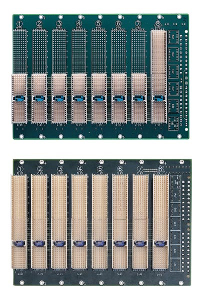
cBP-3204
cPCI 4 slot 32bit backplane ATX
478,00 EUR
inkl. Umsatzsteuer 568,82 EUR
- CompactPCI PICMG 2.0 R2.1 Compliance: Fully compliant with the CompactPCI 32‑bit bus standard, ensuring interoperability with a wide range of CompactPCI CPU and I/O boards.
- Four‑Slot Configuration: One system slot and three peripheral slots, supporting up to four CompactPCI boards in a single 3U chassis.
- High‑Quality PCB Design: 10‑layer printed circuit board for controlled impedance, reduced crosstalk, and improved signal integrity in high‑speed PCI bus environments.
- Power Input Flexibility: Equipped with two ATX‑style DC power connectors and additional screw terminals for direct DC input, allowing flexible integration with standard ATX or industrial power supplies.
- Rear I/O Support (optional): The cBP‑3204R variant includes P2 connectors for rear I/O applications, enabling rear transition modules and enhanced system expandability.
- Selectable I/O Voltage: V(I/O) can be configured for either +3.3 V or +5 V signaling, providing compatibility with a wide range of CompactPCI boards.
- Compact 3U Form Factor: Designed for 3U CompactPCI chassis, suitable for rack‑mount or desktop industrial systems.
- System Slot Orientation: System slot located on the right‑hand side for integration with ADLINK cPCIS‑1000/2000 series chassis.
- Robust Power Distribution: Supports +3.3 V, +5 V, +12 V, and −12 V rails with sense lines and inhibit control for ATX‑type power management.
- Industrial‑Grade Construction: Built for continuous operation in embedded and industrial environments, with high mechanical stability and EMI/EMC compliance.
- Four‑Slot Configuration: One system slot and three peripheral slots, supporting up to four CompactPCI boards in a single 3U chassis.
- High‑Quality PCB Design: 10‑layer printed circuit board for controlled impedance, reduced crosstalk, and improved signal integrity in high‑speed PCI bus environments.
- Power Input Flexibility: Equipped with two ATX‑style DC power connectors and additional screw terminals for direct DC input, allowing flexible integration with standard ATX or industrial power supplies.
- Rear I/O Support (optional): The cBP‑3204R variant includes P2 connectors for rear I/O applications, enabling rear transition modules and enhanced system expandability.
- Selectable I/O Voltage: V(I/O) can be configured for either +3.3 V or +5 V signaling, providing compatibility with a wide range of CompactPCI boards.
- Compact 3U Form Factor: Designed for 3U CompactPCI chassis, suitable for rack‑mount or desktop industrial systems.
- System Slot Orientation: System slot located on the right‑hand side for integration with ADLINK cPCIS‑1000/2000 series chassis.
- Robust Power Distribution: Supports +3.3 V, +5 V, +12 V, and −12 V rails with sense lines and inhibit control for ATX‑type power management.
- Industrial‑Grade Construction: Built for continuous operation in embedded and industrial environments, with high mechanical stability and EMI/EMC compliance.
1. Product Overview
Product Name: cBP‑3204
Article Number: cBP‑3204
Series: cBP‑3200 Series – 3U CompactPCI 32‑bit Backplane with Rear I/O Option
Manufacturer: ADLINK Technology Inc.
Product Type: 4‑slot CompactPCI 32‑bit backplane, ATX‑powered, 3U form factor
Description: The ADLINK cBP‑3204 is a 3U CompactPCI backplane providing four slots (one system slot and three peripheral slots) for 32‑bit PCI bus operation. It is designed for embedded and industrial computing platforms that require a compact, high‑reliability interconnect solution. The backplane supports ATX power input via dual connectors and screw terminals, and is built on a 10‑layer PCB for precise impedance control and signal integrity. The system slot is positioned on the right‑hand side, and the assembly width is 20HP.
2. Key Features
- CompactPCI PICMG 2.0 R2.1 Compliance: Fully compliant with the CompactPCI 32‑bit bus standard, ensuring interoperability with a wide range of CompactPCI CPU and I/O boards.
- Four‑Slot Configuration: One system slot and three peripheral slots, supporting up to four CompactPCI boards in a single 3U chassis.
- High‑Quality PCB Design: 10‑layer printed circuit board for controlled impedance, reduced crosstalk, and improved signal integrity in high‑speed PCI bus environments.
- Power Input Flexibility: Equipped with two ATX‑style DC power connectors and additional screw terminals for direct DC input, allowing flexible integration with standard ATX or industrial power supplies.
- Rear I/O Support (optional): The cBP‑3204R variant includes P2 connectors for rear I/O applications, enabling rear transition modules and enhanced system expandability.
- Selectable I/O Voltage: V(I/O) can be configured for either +3.3 V or +5 V signaling, providing compatibility with a wide range of CompactPCI boards.
- Compact 3U Form Factor: Designed for 3U CompactPCI chassis, suitable for rack‑mount or desktop industrial systems.
- System Slot Orientation: System slot located on the right‑hand side for integration with ADLINK cPCIS‑1000/2000 series chassis.
- Robust Power Distribution: Supports +3.3 V, +5 V, +12 V, and −12 V rails with sense lines and inhibit control for ATX‑type power management.
- Industrial‑Grade Construction: Built for continuous operation in embedded and industrial environments, with high mechanical stability and EMI/EMC compliance.
3. Technical Specifications
- Form Factor: 3U CompactPCI (PICMG 2.0 R2.1 compliant)
- Bus Width: 32‑bit PCI bus on P1 connector
- Number of Slots: 4 total (1 system slot + 3 peripheral slots)
- PCB Layers: 10‑layer design for impedance control
- Dimensions: 133.35 mm (H) × 182.0 mm (W) × 3.2 mm (T)
- Width Allocation: 20HP (approx. 101.6 mm)
- System Slot Position: Right‑hand side
- Power Input Connectors:
- Two ATX‑style 20‑pin connectors (CN1, CN2)
- Screw terminal block for direct DC input (+3.3 V, +5 V, +12 V, −12 V, GND, V(I/O))
- Selectable I/O Voltage: +3.3 V or +5 V (factory default +5 V)
- Power Rails Supported: +3.3 V, +5 V, +12 V, −12 V
- Signal Integrity: Controlled impedance traces, matched length routing for PCI signals
- Material: FR‑4 epoxy glass laminate, industrial‑grade
- PCB Thickness: 3.2 mm nominal
- Operating Temperature: 0 °C to 70 °C (typical system environment)
- Storage Temperature: −40 °C to +85 °C
- Relative Humidity: < 95 % non‑condensing
4. Functionality
The cBP‑3204 serves as the electrical and mechanical backbone of a CompactPCI system, distributing PCI bus signals, power, and control lines between the system controller board and peripheral I/O boards. The backplane provides a 32‑bit PCI bus on the P1 connector for each slot, with optional P2 connectors for rear I/O expansion (on the cBP‑3204R variant).
Use Cases and Applications:
- Embedded control systems
- Industrial automation and instrumentation
- Data acquisition and measurement platforms
- Telecommunications and network appliances
- Compact rack‑mount or portable test systems
Compatibility:
- Fully compatible with ADLINK cPCIS‑1000 and cPCIS‑2000 series chassis
- Supports CompactPCI CPU boards, I/O modules, and rear transition modules compliant with PICMG 2.0 R2.1
- Compatible with ATX or CompactPCI power supplies (31‑pin or 47‑pin via adapter backplanes)
5. Components & Accessories
Included Interfaces:
- Two ATX 20‑pin connectors (CN1, CN2) for DC power input
- Screw terminal block for alternate DC input
- Jumpers for configuration and control:
- JP8: INH# (power inhibit)
- JP9: RST# (system reset)
- JP10: FAL# (power fail input)
- JP7: +12 V sense jumper
Optional Accessories:
- Rear I/O connectors (P2) for cBP‑3204R version
- ATX power supply (e.g., ADLINK APS‑925A 280 W)
- CompactPCI power supply modules (cPS‑150R, cPS‑175 series) via adapter backplanes
- Chassis integration kits (cPCIS‑1000 or cPCIS‑2000)
- Slot panels with EMC gaskets (cPCI‑SP3E)
Connectors and Signals:
- ATX Power Connector (CN1/CN2):
+3.3 V (pins 1, 2, 11), +5 V (pins 4, 6, 20), +12 V (pin 10), −12 V (pin 12), GND (pins 3, 5, 7, 13, 15, 16, 17), INH# (pin 14), FAL# (pin 8), DEG# (pin 9), +5 V Sense (pins 16, 19).
- Screw Terminal Block: +3.3 V, V(I/O), +5 V, GND, +12 V, −12 V.
6. Installation & Setup
Requirements:
- 3U CompactPCI chassis with 20HP slot width (e.g., ADLINK cPCIS‑1000/2000)
- Compatible CompactPCI CPU and peripheral boards
- ATX or CompactPCI‑type power supply
Mounting Options:
- Direct installation into 3U card cage using standard CompactPCI card guides and mounting holes
- System slot positioned on the right‑hand side for ADLINK chassis alignment
Configuration Steps:
1. Mount the backplane into the chassis using standard screws and standoffs.
2. Connect ATX power cables to CN1 and CN2 or wire DC inputs to the screw terminal block.
3. Configure V(I/O) voltage selection (default +5 V; jumper to +3.3 V if required).
4. Connect the system controller board to the system slot (right‑hand side).
5. Install peripheral I/O boards into the remaining three slots.
6. Optionally connect rear I/O modules if using the cBP‑3204R variant.
7. Verify power inhibit (INH#) and reset (RST#) jumper settings before powering on.
7. Performance & Capabilities
- Bus Architecture: 32‑bit PCI bus, 33 MHz operation, compliant with PICMG 2.0 R2.1
- Slot Count: 4 total (1 system, 3 peripheral)
- Signal Integrity: 10‑layer PCB ensures low noise and minimal signal skew across slots
- Power Distribution:
- +3.3 V, +5 V, +12 V, −12 V rails distributed to all slots
- Sense lines for +5 V and +12 V to compensate voltage drop
- Inhibit and fail signals for power management
- Efficiency: Dependent on external PSU; supports high‑efficiency ATX or redundant CompactPCI power modules
- Limitations:
- 32‑bit bus width (no 64‑bit extension)
- Maximum of three peripheral slots
- Rear I/O available only on “R” variant
8. Standards & Compliance
- CompactPCI Standard: PICMG 2.0 Revision 2.1 (32‑bit PCI bus)
- Power Interface Compatibility: ATX 20‑pin connector standard; supports CompactPCI power interface per PICMG 2.11 via adapter backplanes
- Electrical Safety: Designed to meet UL 1950, CSA C22.2 No. 950, EN 60950 (when integrated with certified power supplies)
- EMC/EMI Compliance: Meets EN 55022 Class A/B and FCC Class A/B limits when installed in compliant chassis
- Environmental: Operates within industrial temperature and humidity ranges; conforms to CE and TüV safety directives when used with certified ADLINK components
9. Additional Information
Warranty:
ADLINK provides a one‑year limited warranty covering defects in materials and workmanship from the date of purchase. The warranty excludes damage due to misuse, modification, or operation beyond specified limits.
Support & Service:
- Technical Support: nuipc@adlink.com.tw
- Sales & Service: service@adlink.com.tw
- Website: [www.adlinktech.com](http://www.adlinktech.com) / [www.adlink.com.tw](http://www.adlink.com.tw)
- Telephone: +886‑2‑82265877
- Fax: +886‑2‑82265717
- Address: 9F, No. 166, Jian Yi Road, Chungho City, Taipei 235, Taiwan, R.O.C.
Maintenance:
- Periodically inspect connectors for dust or oxidation.
- Ensure proper airflow within the chassis to maintain thermal stability.
- Verify jumper settings after any system reconfiguration.
Updates & Revisions:
Product specifications are subject to change without notice to improve design and reliability. Users should refer to the latest ADLINK documentation for updated technical data.
Summary:
The ADLINK cBP‑3204 is a compact, high‑reliability 3U CompactPCI backplane optimized for embedded and industrial computing systems requiring a 32‑bit PCI bus architecture. With its four‑slot configuration, robust 10‑layer PCB, flexible ATX power input, and optional rear I/O support, it provides a stable foundation for modular system integration in demanding environments.
Product Name: cBP‑3204
Article Number: cBP‑3204
Series: cBP‑3200 Series – 3U CompactPCI 32‑bit Backplane with Rear I/O Option
Manufacturer: ADLINK Technology Inc.
Product Type: 4‑slot CompactPCI 32‑bit backplane, ATX‑powered, 3U form factor
Description: The ADLINK cBP‑3204 is a 3U CompactPCI backplane providing four slots (one system slot and three peripheral slots) for 32‑bit PCI bus operation. It is designed for embedded and industrial computing platforms that require a compact, high‑reliability interconnect solution. The backplane supports ATX power input via dual connectors and screw terminals, and is built on a 10‑layer PCB for precise impedance control and signal integrity. The system slot is positioned on the right‑hand side, and the assembly width is 20HP.
2. Key Features
- CompactPCI PICMG 2.0 R2.1 Compliance: Fully compliant with the CompactPCI 32‑bit bus standard, ensuring interoperability with a wide range of CompactPCI CPU and I/O boards.
- Four‑Slot Configuration: One system slot and three peripheral slots, supporting up to four CompactPCI boards in a single 3U chassis.
- High‑Quality PCB Design: 10‑layer printed circuit board for controlled impedance, reduced crosstalk, and improved signal integrity in high‑speed PCI bus environments.
- Power Input Flexibility: Equipped with two ATX‑style DC power connectors and additional screw terminals for direct DC input, allowing flexible integration with standard ATX or industrial power supplies.
- Rear I/O Support (optional): The cBP‑3204R variant includes P2 connectors for rear I/O applications, enabling rear transition modules and enhanced system expandability.
- Selectable I/O Voltage: V(I/O) can be configured for either +3.3 V or +5 V signaling, providing compatibility with a wide range of CompactPCI boards.
- Compact 3U Form Factor: Designed for 3U CompactPCI chassis, suitable for rack‑mount or desktop industrial systems.
- System Slot Orientation: System slot located on the right‑hand side for integration with ADLINK cPCIS‑1000/2000 series chassis.
- Robust Power Distribution: Supports +3.3 V, +5 V, +12 V, and −12 V rails with sense lines and inhibit control for ATX‑type power management.
- Industrial‑Grade Construction: Built for continuous operation in embedded and industrial environments, with high mechanical stability and EMI/EMC compliance.
3. Technical Specifications
- Form Factor: 3U CompactPCI (PICMG 2.0 R2.1 compliant)
- Bus Width: 32‑bit PCI bus on P1 connector
- Number of Slots: 4 total (1 system slot + 3 peripheral slots)
- PCB Layers: 10‑layer design for impedance control
- Dimensions: 133.35 mm (H) × 182.0 mm (W) × 3.2 mm (T)
- Width Allocation: 20HP (approx. 101.6 mm)
- System Slot Position: Right‑hand side
- Power Input Connectors:
- Two ATX‑style 20‑pin connectors (CN1, CN2)
- Screw terminal block for direct DC input (+3.3 V, +5 V, +12 V, −12 V, GND, V(I/O))
- Selectable I/O Voltage: +3.3 V or +5 V (factory default +5 V)
- Power Rails Supported: +3.3 V, +5 V, +12 V, −12 V
- Signal Integrity: Controlled impedance traces, matched length routing for PCI signals
- Material: FR‑4 epoxy glass laminate, industrial‑grade
- PCB Thickness: 3.2 mm nominal
- Operating Temperature: 0 °C to 70 °C (typical system environment)
- Storage Temperature: −40 °C to +85 °C
- Relative Humidity: < 95 % non‑condensing
4. Functionality
The cBP‑3204 serves as the electrical and mechanical backbone of a CompactPCI system, distributing PCI bus signals, power, and control lines between the system controller board and peripheral I/O boards. The backplane provides a 32‑bit PCI bus on the P1 connector for each slot, with optional P2 connectors for rear I/O expansion (on the cBP‑3204R variant).
Use Cases and Applications:
- Embedded control systems
- Industrial automation and instrumentation
- Data acquisition and measurement platforms
- Telecommunications and network appliances
- Compact rack‑mount or portable test systems
Compatibility:
- Fully compatible with ADLINK cPCIS‑1000 and cPCIS‑2000 series chassis
- Supports CompactPCI CPU boards, I/O modules, and rear transition modules compliant with PICMG 2.0 R2.1
- Compatible with ATX or CompactPCI power supplies (31‑pin or 47‑pin via adapter backplanes)
5. Components & Accessories
Included Interfaces:
- Two ATX 20‑pin connectors (CN1, CN2) for DC power input
- Screw terminal block for alternate DC input
- Jumpers for configuration and control:
- JP8: INH# (power inhibit)
- JP9: RST# (system reset)
- JP10: FAL# (power fail input)
- JP7: +12 V sense jumper
Optional Accessories:
- Rear I/O connectors (P2) for cBP‑3204R version
- ATX power supply (e.g., ADLINK APS‑925A 280 W)
- CompactPCI power supply modules (cPS‑150R, cPS‑175 series) via adapter backplanes
- Chassis integration kits (cPCIS‑1000 or cPCIS‑2000)
- Slot panels with EMC gaskets (cPCI‑SP3E)
Connectors and Signals:
- ATX Power Connector (CN1/CN2):
+3.3 V (pins 1, 2, 11), +5 V (pins 4, 6, 20), +12 V (pin 10), −12 V (pin 12), GND (pins 3, 5, 7, 13, 15, 16, 17), INH# (pin 14), FAL# (pin 8), DEG# (pin 9), +5 V Sense (pins 16, 19).
- Screw Terminal Block: +3.3 V, V(I/O), +5 V, GND, +12 V, −12 V.
6. Installation & Setup
Requirements:
- 3U CompactPCI chassis with 20HP slot width (e.g., ADLINK cPCIS‑1000/2000)
- Compatible CompactPCI CPU and peripheral boards
- ATX or CompactPCI‑type power supply
Mounting Options:
- Direct installation into 3U card cage using standard CompactPCI card guides and mounting holes
- System slot positioned on the right‑hand side for ADLINK chassis alignment
Configuration Steps:
1. Mount the backplane into the chassis using standard screws and standoffs.
2. Connect ATX power cables to CN1 and CN2 or wire DC inputs to the screw terminal block.
3. Configure V(I/O) voltage selection (default +5 V; jumper to +3.3 V if required).
4. Connect the system controller board to the system slot (right‑hand side).
5. Install peripheral I/O boards into the remaining three slots.
6. Optionally connect rear I/O modules if using the cBP‑3204R variant.
7. Verify power inhibit (INH#) and reset (RST#) jumper settings before powering on.
7. Performance & Capabilities
- Bus Architecture: 32‑bit PCI bus, 33 MHz operation, compliant with PICMG 2.0 R2.1
- Slot Count: 4 total (1 system, 3 peripheral)
- Signal Integrity: 10‑layer PCB ensures low noise and minimal signal skew across slots
- Power Distribution:
- +3.3 V, +5 V, +12 V, −12 V rails distributed to all slots
- Sense lines for +5 V and +12 V to compensate voltage drop
- Inhibit and fail signals for power management
- Efficiency: Dependent on external PSU; supports high‑efficiency ATX or redundant CompactPCI power modules
- Limitations:
- 32‑bit bus width (no 64‑bit extension)
- Maximum of three peripheral slots
- Rear I/O available only on “R” variant
8. Standards & Compliance
- CompactPCI Standard: PICMG 2.0 Revision 2.1 (32‑bit PCI bus)
- Power Interface Compatibility: ATX 20‑pin connector standard; supports CompactPCI power interface per PICMG 2.11 via adapter backplanes
- Electrical Safety: Designed to meet UL 1950, CSA C22.2 No. 950, EN 60950 (when integrated with certified power supplies)
- EMC/EMI Compliance: Meets EN 55022 Class A/B and FCC Class A/B limits when installed in compliant chassis
- Environmental: Operates within industrial temperature and humidity ranges; conforms to CE and TüV safety directives when used with certified ADLINK components
9. Additional Information
Warranty:
ADLINK provides a one‑year limited warranty covering defects in materials and workmanship from the date of purchase. The warranty excludes damage due to misuse, modification, or operation beyond specified limits.
Support & Service:
- Technical Support: nuipc@adlink.com.tw
- Sales & Service: service@adlink.com.tw
- Website: [www.adlinktech.com](http://www.adlinktech.com) / [www.adlink.com.tw](http://www.adlink.com.tw)
- Telephone: +886‑2‑82265877
- Fax: +886‑2‑82265717
- Address: 9F, No. 166, Jian Yi Road, Chungho City, Taipei 235, Taiwan, R.O.C.
Maintenance:
- Periodically inspect connectors for dust or oxidation.
- Ensure proper airflow within the chassis to maintain thermal stability.
- Verify jumper settings after any system reconfiguration.
Updates & Revisions:
Product specifications are subject to change without notice to improve design and reliability. Users should refer to the latest ADLINK documentation for updated technical data.
Summary:
The ADLINK cBP‑3204 is a compact, high‑reliability 3U CompactPCI backplane optimized for embedded and industrial computing systems requiring a 32‑bit PCI bus architecture. With its four‑slot configuration, robust 10‑layer PCB, flexible ATX power input, and optional rear I/O support, it provides a stable foundation for modular system integration in demanding environments.
-
 cBP-3208+3206+3204R_Datasheet_3.pdf
PDF Catalog
cBP-3208+3206+3204R_Datasheet_3.pdf
PDF Catalog

Kein Zubehör vorhanden.