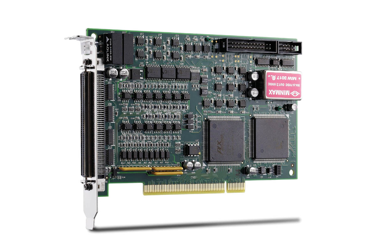
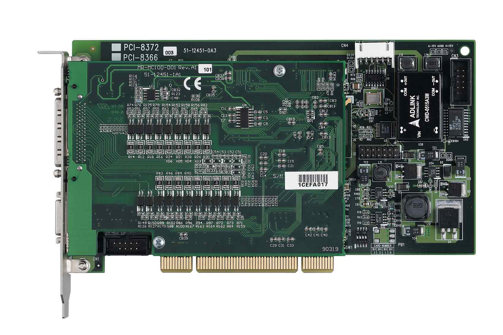
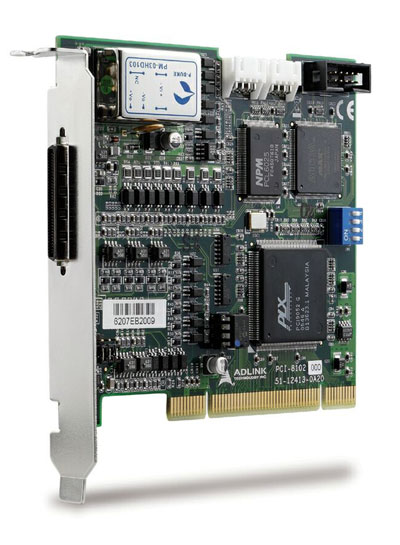
Comprehensive Product Summary – ADLINK PCI-8124 4-Channel Encoder Motion Board
### 1. Product Overview
Product Name: PCI-8124
Model Number: PCI-8124
Series: PCI Encoder/Trigger Motion Control Series
Article Number: PCI-8124
Manufacturer: ADLINK Technology Inc.
Part Number: 50-11138-1000
Manual Revision: Rev. 2.00 (February 12, 2007)
Product Type: 4-Channel Encoder Compare and Trigger Board
Form Factor: 32-bit PCI Bus Card (Rev. 2.2, 33 MHz)
Manufacturer Website: [www.adlinktech.com](http://www.adlinktech.com)
The ADLINK PCI-8124 is a high-performance quadrature encoder counter and trigger output board designed for precision motion control and vision inspection systems. It integrates FPGA-based processing to deliver high-speed encoder input, position comparison, and trigger pulse generation with minimal CPU load. The board supports up to four differential encoder channels and four trigger outputs, making it ideal for machine automation, motion synchronization, and industrial inspection applications.
### 2. Key Features
- PCI Bus Interface:
Compliant with PCI Rev. 2.2, 32-bit, 33 MHz; supports both 3.3V and 5V signaling environments.
Plug-and-Play compatible with automatic resource allocation by system BIOS.
- Encoder Input Channels:
Four 32-bit differential quadrature encoder counter input channels.
Supports AB phase (1x, 2x, 4x), CW/CCW, and OUT/DIR pulse modes.
Maximum encoder input frequency: 10 MHz.
Each channel includes EZ index input for homing and zeroing operations.
- Trigger Output Channels:
Four independent trigger outputs (open collector and TTL).
Maximum trigger output frequency: 5 MHz.
Programmable pulse width from 0.1 µs to 3.2765 ms.
Trigger sources selectable from comparators, manual trigger, EZ signal, or timers.
- Comparators and FIFO:
14 total comparators (4 for FIFO, 10 for linear functions).
4 FIFO buffers (1023 × 32-bit depth each) for high-speed position comparison.
Supports automatic data reloading and continuous triggering.
- Linear Function Generator:
10 independent linear comparison functions for generating continuous trigger sequences.
Supports programmable start point, interval, and repeat count.
- Latch and Timer Functions:
Four high-speed latch inputs for position capture (10 MHz bandwidth).
Four internal 14-bit timers with 400 ns base resolution.
- Isolation and Protection:
Optically isolated encoder, latch, and trigger I/O using PS9115 photo-couplers (2500 Vrms isolation).
TTL I/O available for high-speed non-isolated applications.
- Software and Driver Support:
Windows 2000/XP/Vista WDM driver and DLL library.
Compatible with VB, VC++, BCB, and Delphi programming environments.
- Board Index and Configuration:
4-bit hardware board ID switch (0–15) for multi-board systems (up to 16 boards).
Default trigger level configurable via DIP switch.
### 3. Technical Specifications
Main Chip:
- FPGA: ACTEL A3P1000
- Operating Voltages: 3.3V and 1.5V
- Reference Clock: 40 MHz
Encoder Counters:
- Channels: 4
- Input Type: Differential or single-ended
- Isolation: 2500 Vrms (PS9115 photo-coupler)
- Max Frequency: 10 MHz
- Data Width: 32-bit
- Modes: AB phase (1x/2x/4x), CW/CCW, OUT/DIR
- Zero Operation: EZ input (programmable edge trigger)
Comparators:
- Total: 14 (4 FIFO, 10 linear)
- Data Width: 32-bit
- Trigger Pulse Width: 0.1 µs – 3.2765 ms (programmable)
Timers:
- Quantity: 4
- Base Period: 400 ns
- Resolution: 14-bit
- Start/Stop Control: TTL input or software register
- Output: Trigger or encoder simulation
Trigger Outputs:
- Channels: 4
- Frequency: Up to 5 MHz
- Output Type: Open collector (isolated) or TTL (non-isolated)
- Isolation: 2500 Vrms (PS9115)
- Continuous Triggering: Supported via FIFO or linear function
- Interrupt: Supported on trigger events
FIFO Buffers:
- Quantity: 4
- Depth: 1023 × 32-bit
- Interrupts: Empty, full, or low-level (¼, ½, ¾)
- Auto Reload: Yes
Linear Functions:
- Quantity: 10
- Start Address: 32-bit
- Repeat Count: 32-bit
- Interval: 13-bit
- Direction: 1-bit (positive/negative)
- Interrupt: On completion
- Auto Reload: Yes
Latch Inputs:
- Channels: 4
- Isolation: 2500 Vrms (PS9115)
- Bandwidth: 10 MHz
- Interrupt: On latch event
- Edge Selectable: Rising or falling
TTL I/O:
- Inputs: 4 (general purpose or timer start)
- Outputs: 4 (general purpose or trigger output)
- Max Input Voltage: 4.6 VDC
- Max Output Current: 25 mA per channel
- Max Output Voltage: 5 VDC
Connectors:
- CN1: 50-pin SCSI-type connector (encoder, trigger, latch, TTL I/O)
- CN2: 6-pin header (TTL outputs and +5V supply)
Power Requirements:
- PCI Slot Power: +5V DC ±5%, 450 mA (max)
- +12V DC ±5%, 100 mA (max)
- Isolation Power: Derived from PCI +12V to isolated +5V DC
Environmental:
- Operating Temperature: 0°C to 70°C
- Storage Temperature: -20°C to 80°C
- Humidity: 5–85% RH, non-condensing
Physical:
- Dimensions: 151 mm (L) × 107 mm (W)
- Form Factor: Standard PCI card
### 4. Functionality
The PCI-8124 functions as a high-speed encoder interface and trigger generation board. It captures encoder feedback signals, compares position data against preset values, and outputs synchronized trigger pulses for motion or vision systems.
Operating Modes:
- Encoder Counting: Supports single pulse (OUT/DIR), dual pulse (CW/CCW), and quadrature (AB phase) decoding.
- Position Comparison: Generates trigger pulses when encoder count matches comparator data.
- Continuous Triggering: Achieved via FIFO or linear function reloading.
- Homing: Counter zeroing via EZ index input (rising/falling edge selectable).
- Latch Function: Captures instantaneous position data upon external latch signal.
- Timer Mode: Generates periodic pulses or simulates encoder signals.
- Interrupt Handling: Supports multiple interrupt sources (PWM, FIFO, latch, TTL-IN, linear completion).
Applications:
- Machine vision synchronization (e.g., line-scan camera triggering).
- Precision motion control and servo feedback monitoring.
- Automated inspection and measurement systems.
- Multi-axis motion synchronization in industrial automation.
- Encoder-based position tracking and event triggering.
Compatibility:
- Supports Windows 2000/XP/Vista via ADLINK WDM driver.
- Compatible with ADLINK’s NuDAQ and DAQBench software environments.
- Programmable via C/C++, Visual Basic, Delphi, and Borland C++ Builder.
### 5. Components & Accessories
Included Items:
- PCI-8124 4-Channel Encoder Compare Trigger Board
- ADLINK All-in-One Software CD (drivers, DLLs, documentation)
- User’s Manual (PDF and printed version)
Connectors:
- CN1 (50-pin SCSI): Encoder inputs, trigger outputs, latch inputs, TTL I/O, and ground references.
- CN2 (6-pin header): TTL outputs and +5V power supply.
Optional Accessories:
- SCSI-50 shielded cable assemblies
- Terminal boards for signal breakout
- Mounting brackets for industrial enclosures
### 6. Installation & Setup
Hardware Installation:
1. Power off the PC and disconnect peripherals.
2. Insert the PCI-8124 into an available 32-bit PCI slot (3.3V or 5V).
3. Secure the card with the chassis screw.
4. Power on the system; BIOS will automatically assign resources.
Board Configuration:
- SW1 (Board ID Switch): Sets unique board index (0–15) for multi-board systems.
- SW2 (Default Trigger Level): Defines default TRG output level on power-up (+5V or 0V).
Software Installation:
1. Insert the ADLINK All-in-One CD.
2. Run the installer and follow on-screen instructions.
3. Reboot the system after installation.
4. Verify device recognition in Windows Device Manager.
Signal Wiring:
- Encoder inputs (EA±, EB±, EZ±) connect to differential encoder outputs.
- TRG outputs connect to external devices (e.g., camera trigger input).
- TTL I/O for general-purpose digital control.
- Latch inputs for capturing position data on external events.
### 7. Performance & Capabilities
- Encoder Input Frequency: Up to 10 MHz per channel.
- Trigger Output Frequency: Up to 5 MHz.
- Pulse Width Control: 0.1 µs to 3.2765 ms programmable.
- FIFO Depth: 1023 × 32-bit per channel.
- Linear Function Repeat: Up to 2³² iterations.
- Timer Resolution: 400 ns base, 14-bit counter.
- Interrupt Latency: Hardware-level interrupt generation for real-time response.
- Multi-Board Scalability: Up to 16 boards (64 channels total).
Limitations:
- TTL I/O not isolated; suitable for low-voltage logic only.
- Maximum output current limited to 25 mA per TTL channel.
- Requires Windows OS for driver support (no native Linux driver).
### 8. Standards & Compliance
- Bus Interface: PCI Local Bus Specification Rev. 2.2 compliant.
- Electrical Isolation: 2500 Vrms (photo-coupler PS9115).
- Safety & EMC: Designed for industrial environments; compliant with CE and FCC Class A standards (typical for ADLINK products).
- RoHS Compliance: Manufactured in accordance with environmental directives.
- Software Interface: Windows WDM driver model compliant.
### 9. Additional Information
Warranty:
- Standard 2-year limited warranty (1 year in China).
- Covers manufacturing defects and hardware failures.
- Excludes damage from misuse, improper installation, or environmental factors.
- RMA service available via [http://rma.adlinktech.com/policy](http://rma.adlinktech.com/policy).
Support & Maintenance:
- Technical support via email: [service@adlinktech.com](mailto:service@adlinktech.com)
- Telephone: +886-2-82265877
- Fax: +886-2-82265717
- Address: 9F, No. 166, Jian Yi Road, Chungho City, Taipei 235, Taiwan
- Firmware and driver updates available through ADLINK’s website.
- Regular driver updates ensure compatibility with newer Windows versions.
Maintenance Recommendations:
- Avoid static discharge when handling the board.
- Ensure proper grounding and shielding for encoder and trigger cables.
- Operate within specified temperature and humidity ranges.
- Periodically inspect connectors and cables for wear or oxidation.
Software Development Support:
- Comprehensive DLL function library for system initialization, encoder configuration, PWM control, comparator setup, FIFO/linear comparison, latch, timer, and interrupt management.
- Example code provided for C/C++ and Visual Basic.
- Functions include `_8124_initialSw`, `_8124_set_encoder_input_mode`, `_8124_set_pwm_pulse_width`, `_8124_manual_trigger`, `_8124_get_latch_value`, and `_8124_wait_single_int`.
Error Handling:
- Return codes indicate operational status (e.g., ERR_NoError = 0, ERR_TimeOut = -9).
- Diagnostic functions assist in debugging and system validation.
### Summary
The ADLINK PCI-8124 is a robust, FPGA-based 4-channel encoder and trigger board engineered for high-speed motion control and precision synchronization tasks. Its combination of differential encoder inputs, programmable comparators, FIFO and linear comparison functions, and flexible trigger outputs make it a versatile solution for industrial automation, machine vision, and motion synchronization applications. With comprehensive software support, optical isolation, and multi-board scalability, the PCI-8124 delivers reliable, deterministic performance for demanding real-time control environments.


 SUCHEN SIE DIE PASSENDE
 PCI-8124_Datasheet_4.pdf
PDF Catalog
PCI-8124_Datasheet_4.pdf
PDF Catalog
 PCI-8124_Manual_5.pdf
Manual
PCI-8124_Manual_5.pdf
Manual