Comprehensive Product Summary – ADLINK PCI‑8133 Encoder and PWM Motion Control Card
### 1. Product Overview
Product Name: PCI‑8133
Model: PCI‑8133
Series: ADLINK PCI Motion Control / Encoder Counter Series
Article Number: PCI‑8133
Manufacturer: ADLINK Technology Inc. (Taipei, Taiwan)
Product Description:
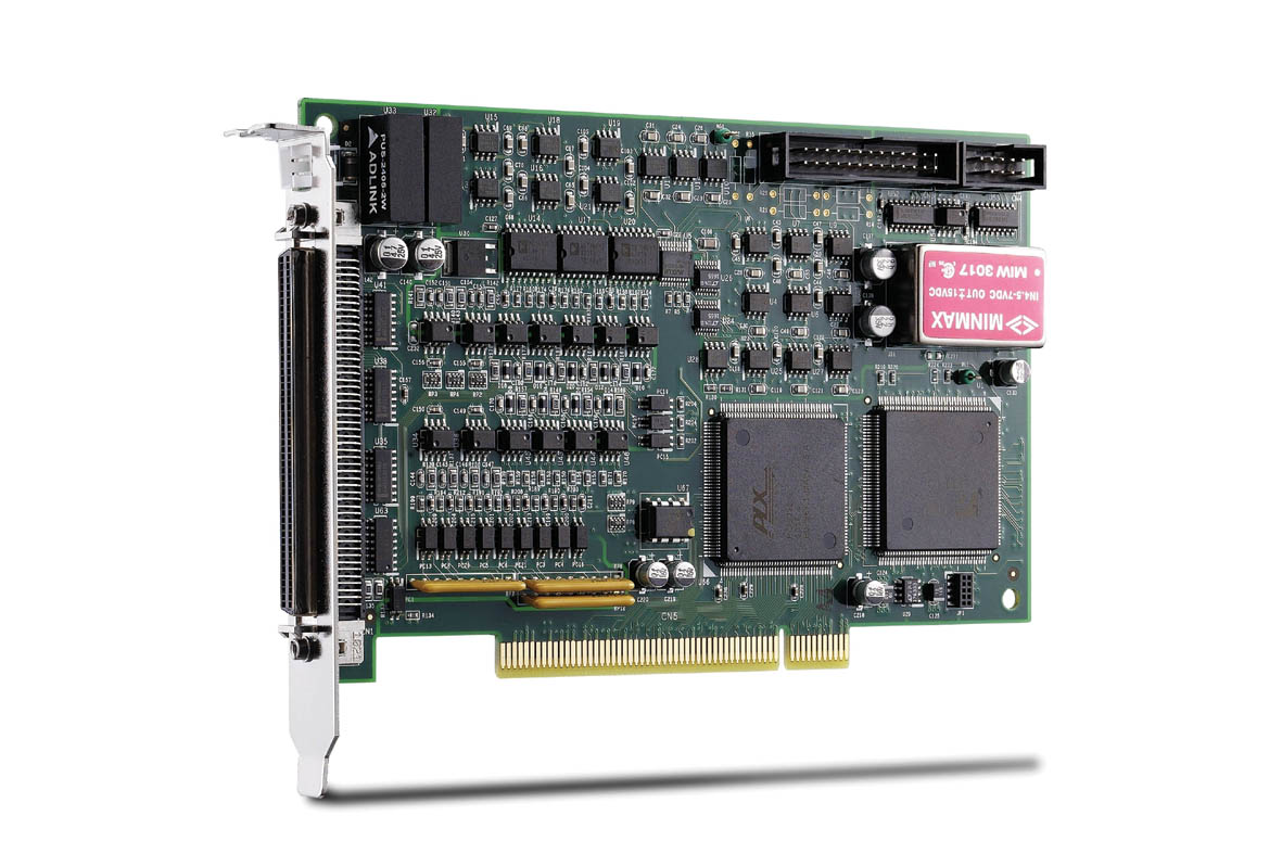
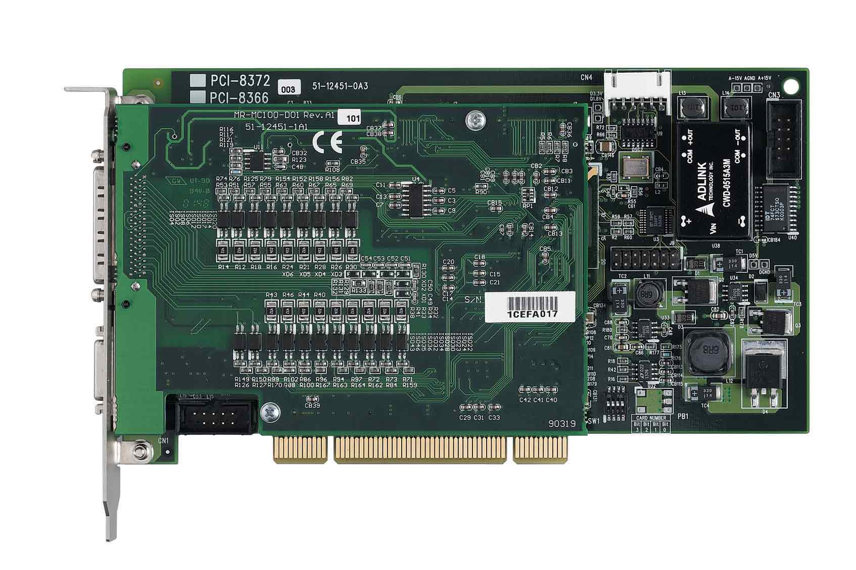
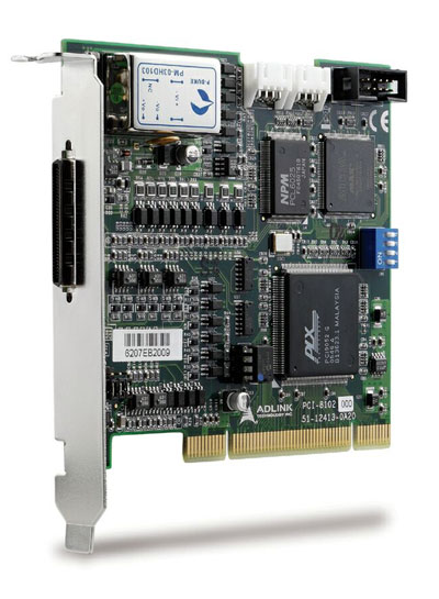
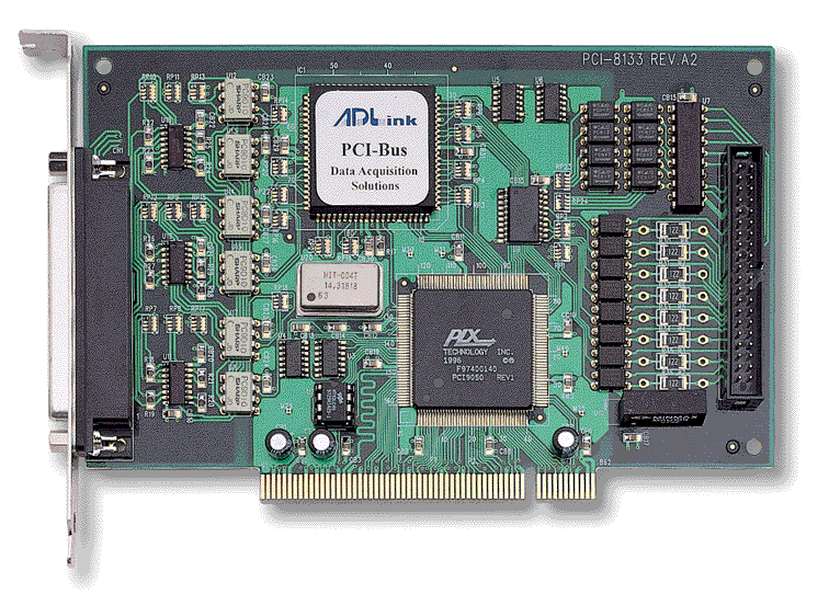
The ADLINK PCI‑8133 is a high‑performance, three‑channel quadrature encoder and PWM output card designed for motion control, position monitoring, and industrial automation applications. It interfaces with a 32‑bit PCI Plug‑and‑Play (PnP) bus and integrates three 16‑bit up/down encoder counters, three 12‑bit PWM waveform generators, and isolated digital I/O channels. The card provides robust electrical isolation (5000 V rms) and programmable digital filtering for noise suppression, making it suitable for precision motor control and feedback systems.
### 2. Key Features
- PCI Bus Interface:
Fully compliant 32‑bit PCI PnP interface for easy installation and automatic resource allocation.
- Encoder Counter System:
- Three independent 16‑bit up/down counters.
- Quadrature (A/B phase) decoding with ×4 resolution multiplication.
- Programmable third‑order digital de‑glitch filters for noise suppression.
- Supports A/B phase, pulse/direction, and CW/CCW input modes.
- Index latch registers for precise position referencing.
- PWM Generation:
- Three 12‑bit PWM waveform generators (U, V, W channels).
- Complementary outputs with programmable dead‑time control.
- Base frequency: 10 MHz.
- PWM synchronized with interrupt timing for deterministic control.
- Digital I/O:
- 11 isolated digital inputs (DI) and 8 isolated digital outputs (DO).
- Input voltage range: 0 – 24 V DC.
- Output type: open‑collector Darlington transistors, up to 40 V DC, 500 mA per channel.
- 5000 V rms isolation between field and logic circuits.
- Interrupt System:
- Dual programmable interrupt timers (INT0 and INT1).
- Adjustable interrupt periods from 0.1 µs to 6.5 ms (INT0) and up to 1.7 s (INT1).
- Single PCI IRQ level with dual interrupt sources.
- Compact Design:
Half‑size PCI card (162 mm × 105 mm) suitable for standard PC enclosures.
- Connectors:
- One 37‑pin D‑type female connector (encoder and PWM signals).
- One 40‑pin flat‑cable header (digital I/O).
- Software Support:
- Drivers and libraries for MS‑DOS (Borland C++) and Windows 95.
- C/C++ and Visual Basic APIs for high‑level control.
- Example programs and DLLs included.
### 3. Technical Specifications
Encoder Counters:
- Channels: 3
- Resolution: 16 bits (0 – 65535)
- Input types: A/B phase, pulse/direction, CW/CCW
- Digital filter: 3‑stage programmable (10 MHz, 5 MHz, 2.5 MHz, 625 kHz)
- Isolation: 5000 V rms
- Input impedance: 220 Ω differential
- Index latch: 1 per channel
PWM Output:
- Channels: 3 (U, V, W)
- Resolution: 12 bits
- Base frequency: 10 MHz
- Output type: open‑collector, 20 mA sink current
- Complementary pairs: (UU/UD), (VU/VD), (WU/WD)
- Programmable dead‑time: 0.75 × (m + 1) µs (0 < m < 256)
Digital I/O:
- Inputs: 11 DI (8 standard + 3 extra differential)
- Input voltage: 0 – 24 V DC
- Logic H: 3 – 24 V
- Logic L: 0 – 1.5 V
- Input resistance: 1.2 kΩ @ 0.5 W
- Outputs: 8 DO (open‑collector Darlington)
- Max voltage: 40 V DC
- Sink current: 345 mA typical, 500 mA max
- Isolation: 5000 V rms
Electrical & Environmental:
- Power consumption: +5 V @ 580 mA (typical)
- Operating temperature: 0 – 55 °C
- Storage temperature: –20 – 80 °C
- Humidity: 0 – 95 % RH (non‑condensing)
- Dimensions: 162 mm × 105 mm
- PCB type: half‑size PCI
Connectors:
- CN1: 37‑pin D‑type (encoder + PWM)
- CN2: 40‑pin header (digital I/O)
### 4. Functionality
Operating Principle:
The PCI‑8133 interfaces with motion control systems by reading encoder feedback and generating PWM control signals. Each encoder channel counts quadrature pulses to determine position and direction, while the PWM generators produce complementary control signals for motor drivers or analog conversion.
Use Cases:
- Servo and stepper motor control
- Position and velocity feedback systems
- Industrial process automation
- Robotics and CNC machinery
- Optical‑mechanical position monitoring
Compatibility:
- PCI 2.1 compliant 32‑bit bus
- Supported OS: MS‑DOS, Windows 95
- Compatible with ADLINK terminal boards (ACLD‑9137, ACLD‑9188)
Signal Processing:
- Differential encoder inputs converted to single‑ended via isolation amplifiers.
- Three‑stage digital filters remove noise spikes.
- Quadrature decoder multiplies resolution × 4.
- Position counters latch data synchronously with index pulses.
- PWM outputs synchronized with INT0 timer for deterministic timing.
### 5. Components & Accessories
Included Items:
- PCI‑8133 motion control card
- “PCI‑8133 Library & Utility” software diskette or CD
- User’s manual
Optional Accessories:
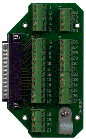
- ACLD‑9137: 37‑pin D‑sub direct connection board.
- ACLD‑9188: 37‑pin D‑sub screw‑terminal board for field wiring.
Connectors and Pinouts:
- CN1 (37‑pin D‑type): Encoder A/B/C inputs, index signals, PWM U/V/W outputs, isolated grounds.
- CN2 (40‑pin header): 8 isolated DI, 8 isolated DO, VPP flywheel power, VDD supply.
### 6. Installation & Setup
System Requirements:
- Available 32‑bit PCI slot.
- +5 V DC supply (580 mA typical).
- Windows 95 or MS‑DOS environment for driver support.
Installation Steps:
1. Power off the PC and discharge static electricity.
2. Insert the PCI‑8133 into an available PCI slot.
3. Boot the system; Plug‑and‑Play BIOS assigns resources automatically.
4. For Windows 95, install the driver using “Pci8133.inf” from the ADLINK CD.
5. Verify installation via Device Manager.
Mounting:
Half‑size PCI card fits standard PC chassis. Use anti‑static precautions during handling.
Configuration:
- No jumpers or DIP switches; all configuration handled by BIOS and software.
- Interrupts and base addresses assigned dynamically.
### 7. Performance & Capabilities
Encoder Performance:
- 16‑bit resolution per channel (0 – 65535).
- Quadrature decoding provides ×4 resolution enhancement.
- Programmable digital filter frequencies (10 MHz → 625 kHz).
- Supports high‑speed encoders up to 1 MHz input frequency.
PWM Performance:
- 12‑bit resolution with 10 MHz base clock.
- Complementary outputs with programmable dead‑time.
- PWM frequency synchronized to INT0 (half of INT0 frequency).
- Suitable for 3‑phase inverter or DAC applications.
Interrupt System:
- Dual interrupt timers (INT0 16‑bit, INT1 8‑bit).
- INT0 period = 0.1 µs × Timer Value (0 – 65535).
- INT1 = INT0 × (n + 1), 0 < n < 256.
- Single PCI IRQ line with dual interrupt sources.
Digital I/O Performance:
- Fast isolated input response.
- High‑current open‑collector outputs for relay or optocoupler driving.
Limitations:
- 16‑bit counter range requires software ISR for extended position tracking.
- PWM outputs are open‑collector; external pull‑ups required for analog conversion.
- Designed for 5 V PCI systems (not PCIe).
### 8. Standards & Compliance
- Bus Interface: PCI 2.1 compliant, 32‑bit, 33 MHz.
- Electrical Isolation: 5000 V rms (optical isolation).
- Safety & EMC: Designed for industrial environments; conforms to ADLINK internal quality standards.
- Software Interface: C/C++ and Visual Basic APIs; Borland C++ and Microsoft Visual C++ compatible.
- Operating System Support: MS‑DOS, Windows 95.
- Environmental Compliance: 0 – 55 °C operation, non‑condensing humidity ≤ 95 %.
### 9. Additional Information
Warranty:
One‑year limited warranty from date of purchase covering defects in materials and workmanship. Warranty excludes damage from misuse, modification, or operation beyond specifications.
Service & Support:
- Technical support via ADLINK authorized distributors.
- Return merchandise authorization (RMA) required for repairs.
- Customer responsible for insured, prepaid shipping.
Maintenance:
- Keep card free from dust and moisture.
- Avoid electrostatic discharge during handling.
- Periodically inspect connectors and cables for wear.
Software Updates:
- Driver and library updates available from ADLINK support.
- Example source code and DLLs provided for integration.
Documentation:
- User’s Manual Rev. 1.00 (Dec 21, 1998).
- Includes register maps, pin assignments, and programming references.
### Summary
The ADLINK PCI‑8133 is a robust, industrial‑grade motion control interface card integrating three 16‑bit quadrature encoder counters, three 12‑bit PWM generators, and isolated digital I/O within a compact PCI form factor. Its 5000 V rms isolation, programmable digital filters, and dual interrupt system make it ideal for precision motor control, servo feedback, and automation tasks. With comprehensive C/C++ and Visual Basic libraries, the PCI‑8133 provides developers with both low‑level register access and high‑level APIs for rapid application development.
Engineered for reliability and flexibility, the PCI‑8133 remains a versatile solution for legacy PCI‑based motion control systems requiring deterministic timing, high‑resolution feedback, and electrically isolated I/O.


 SUCHEN SIE DIE PASSENDE
 P8133 Manual.PDF
Manual
P8133 Manual.PDF
Manual