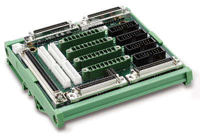
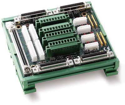
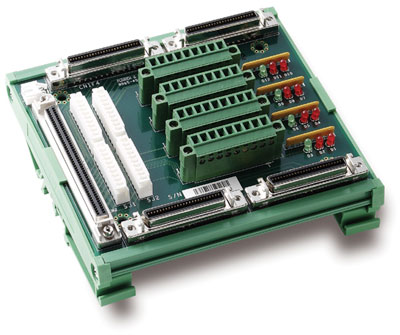
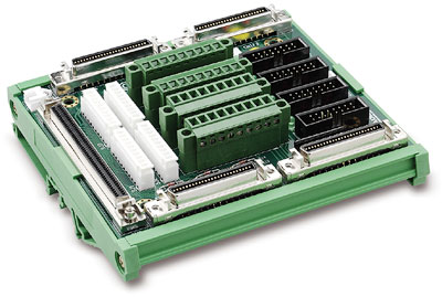
DIN-100S-01
SUCHEN SIE DIE PASSENDE
INDUSTRIELLE LÖSUNG?
Entdecken Sie Embedded-, Kommunikations- und Automatisierungslösungen für Ihre Anwendung.
- PCI Express x1 lane interface for high‑speed data throughput and plug‑and‑play configuration.
- 8‑axis control for stepper or servo motors with pulse‑train input drivers.
- Pulse output rate up to 6.55 MHz, supporting OUT/DIR, CW/CCW, and AB‑phase modes.
- Linear, circular, and helical interpolation across 2–4 axes for complex motion trajectories.
- Multi‑axis continuous interpolation for contour following and smooth path transitions.
- Position and speed override on the fly for dynamic motion adjustment.
- Hardware emergency input and software security protection (EEPROM‑based).
- Supports up to 12 cards per system, enabling control of up to 96 axes.
- 16‑channel TTL digital inputs and 16‑channel TTL digital outputs, optically isolated to 2500 Vrms.
- High‑speed encoder feedback up to 6.55 MHz (4×AB phase).
- 13 home return modes, hardware backlash compensation, and vibration suppression.
- Trapezoidal and S‑curve velocity profiles for smooth acceleration/deceleration.
- Simultaneous start/stop synchronization across multiple axes or cards.
- Manual pulse generator (MPG) interface for manual positioning.
- Comprehensive software support including MotionCreatorPro2, Windows and Linux SDKs, and sample code for VC++, C#, and VB.NET.
- Compatible servo brands: Mitsubishi MR‑J3A/J4A, Panasonic MINAS A4/A5, Yaskawa Sigma V, and any pulse‑train‑controlled servo/stepper drive.
- 8‑axis control for stepper or servo motors with pulse‑train input drivers.
- Pulse output rate up to 6.55 MHz, supporting OUT/DIR, CW/CCW, and AB‑phase modes.
- Linear, circular, and helical interpolation across 2–4 axes for complex motion trajectories.
- Multi‑axis continuous interpolation for contour following and smooth path transitions.
- Position and speed override on the fly for dynamic motion adjustment.
- Hardware emergency input and software security protection (EEPROM‑based).
- Supports up to 12 cards per system, enabling control of up to 96 axes.
- 16‑channel TTL digital inputs and 16‑channel TTL digital outputs, optically isolated to 2500 Vrms.
- High‑speed encoder feedback up to 6.55 MHz (4×AB phase).
- 13 home return modes, hardware backlash compensation, and vibration suppression.
- Trapezoidal and S‑curve velocity profiles for smooth acceleration/deceleration.
- Simultaneous start/stop synchronization across multiple axes or cards.
- Manual pulse generator (MPG) interface for manual positioning.
- Comprehensive software support including MotionCreatorPro2, Windows and Linux SDKs, and sample code for VC++, C#, and VB.NET.
- Compatible servo brands: Mitsubishi MR‑J3A/J4A, Panasonic MINAS A4/A5, Yaskawa Sigma V, and any pulse‑train‑controlled servo/stepper drive.
Comprehensive Product Summary – ADLINK PCIe‑8158 8‑Axis Servo/Stepper Motion Controller
### 1. Product Overview
Product Name: PCIe‑8158
Model: PCIe‑8158
Series: PCIe‑8154 / PCIe‑8158 Advanced Servo & Stepper Motion Controllers
Article Number: PCIe‑8158
Manufacturer: ADLINK Technology, Inc.
Part Number: 50‑11262‑1000
Manual Revision: 2.00 (November 18, 2016)
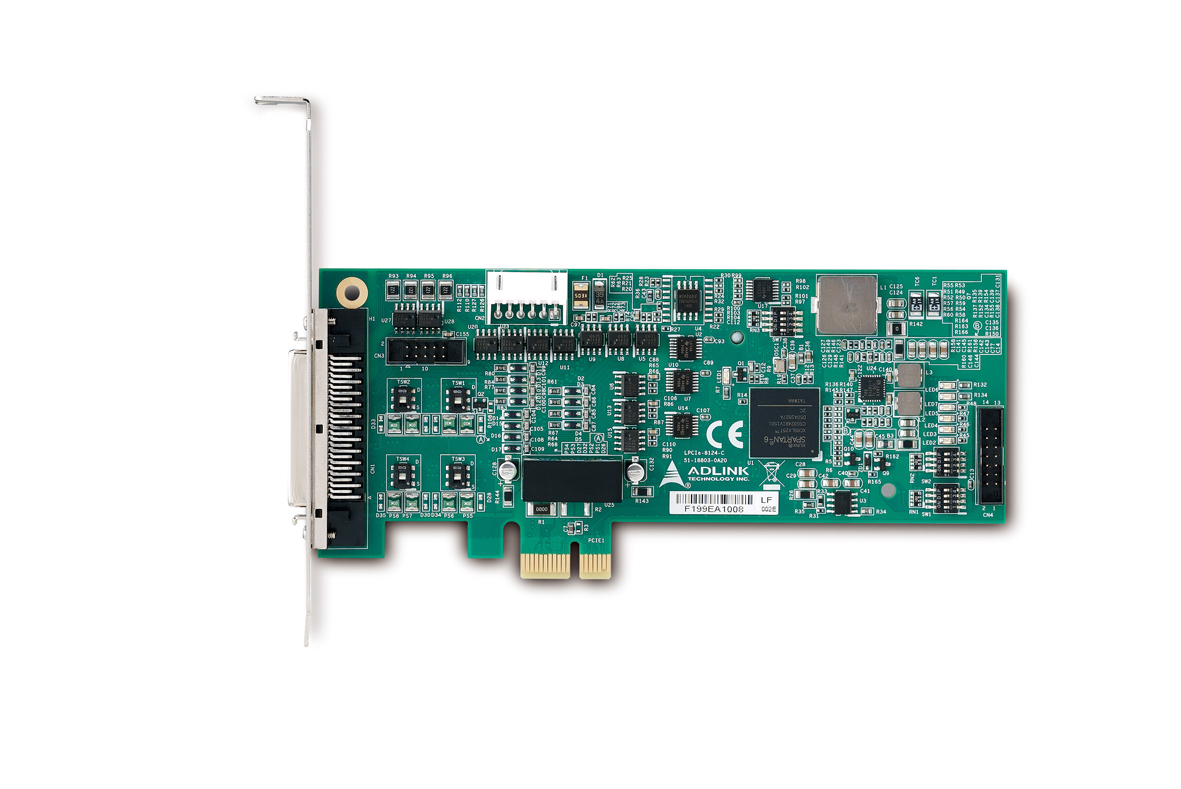
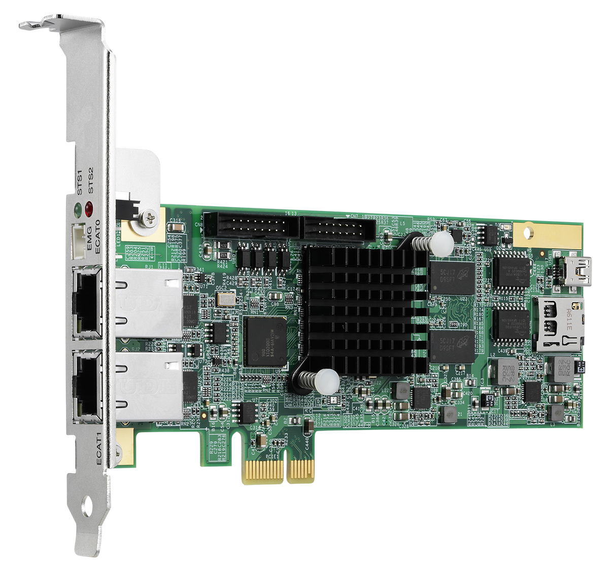
The ADLINK PCIe‑8158 is a high‑performance, modularized 8‑axis motion control card designed for precise control of servo and stepper motors via a PCI Express x1 interface. It provides advanced motion functions such as multi‑axis interpolation, helical and circular motion, and continuous contouring. The controller is engineered for industrial automation, semiconductor equipment, and precision manufacturing systems requiring synchronized, high‑speed, multi‑axis motion.
### 2. Key Features
- PCI Express x1 lane interface for high‑speed data throughput and plug‑and‑play configuration.
- 8‑axis control for stepper or servo motors with pulse‑train input drivers.
- Pulse output rate up to 6.55 MHz, supporting OUT/DIR, CW/CCW, and AB‑phase modes.
- Linear, circular, and helical interpolation across 2–4 axes for complex motion trajectories.
- Multi‑axis continuous interpolation for contour following and smooth path transitions.
- Position and speed override on the fly for dynamic motion adjustment.
- Hardware emergency input and software security protection (EEPROM‑based).
- Supports up to 12 cards per system, enabling control of up to 96 axes.
- 16‑channel TTL digital inputs and 16‑channel TTL digital outputs, optically isolated to 2500 Vrms.
- High‑speed encoder feedback up to 6.55 MHz (4×AB phase).
- 13 home return modes, hardware backlash compensation, and vibration suppression.
- Trapezoidal and S‑curve velocity profiles for smooth acceleration/deceleration.
- Simultaneous start/stop synchronization across multiple axes or cards.
- Manual pulse generator (MPG) interface for manual positioning.
- Comprehensive software support including MotionCreatorPro2, Windows and Linux SDKs, and sample code for VC++, C#, and VB.NET.
- Compatible servo brands: Mitsubishi MR‑J3A/J4A, Panasonic MINAS A4/A5, Yaskawa Sigma V, and any pulse‑train‑controlled servo/stepper drive.
### 3. Technical Specifications
Applicable Motors:
- Stepper motors
- AC/DC servomotors with pulse‑train input servo drivers
Performance:
- Axes: 8 independent motion channels
- Pulse Output Frequency: 0.01 pps – 6.55 Mpps
- Acceleration Rate: up to 245 Mpps²
- Speed Resolution: 16‑bit
- Encoder Input Rate: 6.55 MHz (4×AB phase, 1 m cable)
- Encoder Counter Resolution: 28‑bit
- Positioning Range: ±134,217,727 pulses (28‑bit)
- Counters per Axis: 4
- Comparators per Axis: 5
Electrical & I/O:
- Digital Inputs: 16 × TTL, optically isolated (2500 Vrms)
- Digital Outputs: 16 × TTL, optically isolated (2500 Vrms)
- Encoder Inputs: Differential EA, EB, EZ signals
- Servo Interface I/O: INP, ALM, ERC, RDY, SVON
- Mechanical Inputs: ±EL (end limits), ORG (origin), SD (slow‑down)
- General I/O: DO/CMP, DI/LTC/PCS/CLR/EMG
- Pulser Inputs: PA, PB (manual pulse generator)
- Simultaneous Start/Stop: STA, STP
- Connector Type: 100‑pin SCSI‑II (CN2 main I/O), 44‑pin TTL I/O (CN5)
Power Requirements:
- PCIe slot input: +12 V DC ± 5 %, 400 mA max
- External input: +24 V DC ± 5 %, 500 mA max
- External output: +5 V DC ± 5 %, 300 mA max
Environmental:
- Operating Temperature: 0 °C – 50 °C
- Storage Temperature: –20 °C – 80 °C
- Humidity: 5 – 85 % RH, non‑condensing
Physical:
- Dimensions: 185 mm (L) × 98.4 mm (H)
- Form Factor: PCI Express x1 card
### 4. Functionality
The PCIe‑8158 generates high‑frequency pulse trains to control servo or stepper drives. Each axis outputs differential pulse and direction signals (OUT±, DIR±) configurable as CW/CCW or AB‑phase. Encoder feedback (EA, EB, EZ) provides closed‑loop position verification. The onboard FPGA executes motion profiles—trapezoidal or S‑curve—independently of the host CPU, minimizing system load.
Supported Motion Types:
- Single‑axis: absolute/relative positioning, velocity mode, home return
- Multi‑axis: 2–4‑axis linear interpolation, 2‑axis circular interpolation, 3‑axis helical interpolation
- Continuous contouring: seamless path blending for machining or inspection
- Manual control: via MPG inputs for jog or teach operations
Applications:
- Semiconductor wafer handling and inspection
- CNC and precision machining
- Pick‑and‑place robotics
- Automated optical inspection (AOI)
- Packaging and labeling systems
- Multi‑axis synchronization in assembly automation
Compatibility:
Works with Windows 7/10, Linux, and RTX 8.1a/2009 environments. Supports VC++, C#, VB.NET APIs and ADLINK MotionCreatorPro2 GUI for configuration, testing, and debugging.
### 5. Components & Accessories
Included Items:
- PCIe‑8158 motion control card
- General‑purpose TTL I/O cable (CN5)
- Quick Start Guide
- Software SDK and documentation
Optional Terminal Boards:
- DIN‑100S‑01: 100‑pin SCSI‑II, DIN‑rail mount terminal board
- DIN‑814‑GP: General‑purpose 100‑pin terminal board
- DIN‑814M‑J3A0: For Mitsubishi MR‑J3A/J4A servo amplifiers
- DIN‑814Y0: For Yaskawa Sigma V servo amplifiers
- DIN‑814P‑A40: For Panasonic MINAS A4/A5 servo amplifiers
Cables:
- ACL‑102100‑1: 100‑pin SCSI‑II cable (1 m, AMP‑787082‑9 compatible)
- SCSI‑VHDCI 100P: 100‑pin VHDCI cable (2 m / 3 m lengths)
- DB37FM‑IDC44 Fcable L250: 44‑pin flat cable for TTL I/O
### 6. Installation & Setup
Hardware Installation:
1. Power off the host PC and peripherals.
2. Insert the PCIe‑8158 into any available PCIe slot.
3. Secure the bracket and reconnect power.
4. BIOS automatically assigns I/O and IRQ resources (Plug‑and‑Play).
Configuration:
- Card Index (SW1): DIP switch selectable 0–15 for multi‑card systems.
- Pulse Output Mode (J1–J16): Select differential line driver (default) or open‑collector output per axis.
- External Power: +24 V DC for I/O isolation; +5 V DC output available for encoders.
Software Setup:
- Install ADLINK PCIe‑8158 SDK and drivers.
- Use MotionCreatorPro2 for axis configuration, I/O logic setup, and motion testing.
- Libraries and sample code provided for Windows and Linux development.
Signal Connections:
- CN2: Motion I/O (OUT/DIR, EA/EB/EZ, ORG, ±EL, INP, ALM, SVON, ERC, RDY, DO/CMP, DI/LTC/SD/PCS/CLR/EMG).
- CN5: 16 × TTL inputs (EDI0–15) and 16 × TTL outputs (EDO0–15).
- K1/K2: Simultaneous start/stop connectors for multi‑card synchronization.
- P1: Manual pulse generator interface (PA±, PB±).
### 7. Performance & Capabilities
- Maximum Pulse Output: 6.55 MHz per axis
- Encoder Feedback: 6.55 MHz (4×AB phase)
- Acceleration/Deceleration: Programmable trapezoidal or S‑curve profiles
- Interpolation: 2–4‑axis linear, 2‑axis circular, 3‑axis helical
- Home Return: 13 configurable modes with auto‑search and EZ index support
- Backlash Compensation: Hardware‑based corrective pulses
- Vibration Suppression: Programmable reverse/forward timing (1.6 µs resolution)
- Soft Limits: Programmable ±software limits per axis
- Interrupts: Configurable motion and error interrupts (up to 32 factors)
- Simultaneous Operation: Multi‑axis start/stop across cards via STA/STP lines
- Position Compare & Latch: 5 comparators and 4 counters per axis for high‑speed triggering
- I/O Isolation: 2500 Vrms optical isolation for all motion I/O lines
- Manual Pulse Generator: Supports 1×/2×/4× AB phase or CW/CCW input modes
- Security: EEPROM‑stored 16‑bit key for software protection
Limitations:
- Open‑collector outputs limited to 20 mA sink current.
- Encoder differential input requires ≥ 3.5 V differential amplitude.
- Operating temperature limited to 50 °C ambient.
### 8. Standards & Compliance
- Interface Standard: PCI Express x1 (compliant with PCIe Base Specification)
- Isolation Voltage: 2500 Vrms (optical isolation)
- Environmental Compliance: RoHS and WEEE directives
- Safety: Designed for installation in controlled industrial environments
- EMC: Meets industrial immunity and emission standards (per ADLINK manufacturing policy)
ADLINK emphasizes environmental responsibility and ensures all materials and processes comply with EU RoHS and WEEE directives. Products are designed for minimal environmental impact and safe end‑of‑life disposal.
### 9. Additional Information
Software & Development Tools:
- MotionCreatorPro / MotionCreatorPro2: Windows‑based configuration and debugging utility.
- Programming Libraries: DLLs for Windows 7/8/10, Linux drivers, and RTX 8.1a/2009 support.
- Languages: VC++, C#, VB.NET; sample source code included.
- Function Library: Over 200 API functions for motion control, I/O, interrupts, and diagnostics.
Maintenance & Support:
- Firmware and driver updates available via [www.adlinktech.com](http://www.adlinktech.com).
- Technical support through ADLINK’s global service centers and “Ask an Expert” portal.
- Recommended periodic inspection of connectors and cables for secure contact.
Warranty:
Standard ADLINK limited warranty (refer to regional terms). Covers manufacturing defects; excludes damage from improper installation or environmental misuse.
Service Contacts (Global):
- Headquarters (Taiwan): +886‑2‑8226‑5877 | service@adlinktech.com
- USA: +1‑408‑360‑0200 | info@adlinktech.com
- China (Shanghai/Beijing/Shenzhen): +86‑21‑5132‑8988 | market@adlinktech.com
- Europe (Germany/France/UK): emea@adlinktech.com
- Japan: japan@adlinktech.com
- Korea: korea@adlinktech.com
- Singapore/India: singapore@adlinktech.com | india@adlinktech.com
Environmental & Safety Notes:
- Operate within specified temperature/humidity limits.
- Avoid exposure to liquids, dust, or corrosive environments.
- Disconnect power before installation or maintenance.
- Observe ESD precautions when handling the card.
- Lithium backup battery (if present) must be replaced with identical type only.
### Summary
The ADLINK PCIe‑8158 is a robust, high‑precision 8‑axis motion controller optimized for industrial automation requiring synchronized, high‑speed motion. Its combination of 6.55 MHz pulse output, 28‑bit encoder feedback, and advanced interpolation capabilities enables complex multi‑axis trajectories with minimal CPU overhead. With comprehensive software tools, extensive I/O, and compatibility with major servo brands, the PCIe‑8158 provides a scalable, reliable foundation for demanding motion control applications in manufacturing, robotics, and inspection systems.

### 1. Product Overview
Product Name: PCIe‑8158
Model: PCIe‑8158
Series: PCIe‑8154 / PCIe‑8158 Advanced Servo & Stepper Motion Controllers
Article Number: PCIe‑8158
Manufacturer: ADLINK Technology, Inc.
Part Number: 50‑11262‑1000
Manual Revision: 2.00 (November 18, 2016)
The ADLINK PCIe‑8158 is a high‑performance, modularized 8‑axis motion control card designed for precise control of servo and stepper motors via a PCI Express x1 interface. It provides advanced motion functions such as multi‑axis interpolation, helical and circular motion, and continuous contouring. The controller is engineered for industrial automation, semiconductor equipment, and precision manufacturing systems requiring synchronized, high‑speed, multi‑axis motion.
### 2. Key Features
- PCI Express x1 lane interface for high‑speed data throughput and plug‑and‑play configuration.
- 8‑axis control for stepper or servo motors with pulse‑train input drivers.
- Pulse output rate up to 6.55 MHz, supporting OUT/DIR, CW/CCW, and AB‑phase modes.
- Linear, circular, and helical interpolation across 2–4 axes for complex motion trajectories.
- Multi‑axis continuous interpolation for contour following and smooth path transitions.
- Position and speed override on the fly for dynamic motion adjustment.
- Hardware emergency input and software security protection (EEPROM‑based).
- Supports up to 12 cards per system, enabling control of up to 96 axes.
- 16‑channel TTL digital inputs and 16‑channel TTL digital outputs, optically isolated to 2500 Vrms.
- High‑speed encoder feedback up to 6.55 MHz (4×AB phase).
- 13 home return modes, hardware backlash compensation, and vibration suppression.
- Trapezoidal and S‑curve velocity profiles for smooth acceleration/deceleration.
- Simultaneous start/stop synchronization across multiple axes or cards.
- Manual pulse generator (MPG) interface for manual positioning.
- Comprehensive software support including MotionCreatorPro2, Windows and Linux SDKs, and sample code for VC++, C#, and VB.NET.
- Compatible servo brands: Mitsubishi MR‑J3A/J4A, Panasonic MINAS A4/A5, Yaskawa Sigma V, and any pulse‑train‑controlled servo/stepper drive.
### 3. Technical Specifications
Applicable Motors:
- Stepper motors
- AC/DC servomotors with pulse‑train input servo drivers
Performance:
- Axes: 8 independent motion channels
- Pulse Output Frequency: 0.01 pps – 6.55 Mpps
- Acceleration Rate: up to 245 Mpps²
- Speed Resolution: 16‑bit
- Encoder Input Rate: 6.55 MHz (4×AB phase, 1 m cable)
- Encoder Counter Resolution: 28‑bit
- Positioning Range: ±134,217,727 pulses (28‑bit)
- Counters per Axis: 4
- Comparators per Axis: 5
Electrical & I/O:
- Digital Inputs: 16 × TTL, optically isolated (2500 Vrms)
- Digital Outputs: 16 × TTL, optically isolated (2500 Vrms)
- Encoder Inputs: Differential EA, EB, EZ signals
- Servo Interface I/O: INP, ALM, ERC, RDY, SVON
- Mechanical Inputs: ±EL (end limits), ORG (origin), SD (slow‑down)
- General I/O: DO/CMP, DI/LTC/PCS/CLR/EMG
- Pulser Inputs: PA, PB (manual pulse generator)
- Simultaneous Start/Stop: STA, STP
- Connector Type: 100‑pin SCSI‑II (CN2 main I/O), 44‑pin TTL I/O (CN5)
Power Requirements:
- PCIe slot input: +12 V DC ± 5 %, 400 mA max
- External input: +24 V DC ± 5 %, 500 mA max
- External output: +5 V DC ± 5 %, 300 mA max
Environmental:
- Operating Temperature: 0 °C – 50 °C
- Storage Temperature: –20 °C – 80 °C
- Humidity: 5 – 85 % RH, non‑condensing
Physical:
- Dimensions: 185 mm (L) × 98.4 mm (H)
- Form Factor: PCI Express x1 card
### 4. Functionality
The PCIe‑8158 generates high‑frequency pulse trains to control servo or stepper drives. Each axis outputs differential pulse and direction signals (OUT±, DIR±) configurable as CW/CCW or AB‑phase. Encoder feedback (EA, EB, EZ) provides closed‑loop position verification. The onboard FPGA executes motion profiles—trapezoidal or S‑curve—independently of the host CPU, minimizing system load.
Supported Motion Types:
- Single‑axis: absolute/relative positioning, velocity mode, home return
- Multi‑axis: 2–4‑axis linear interpolation, 2‑axis circular interpolation, 3‑axis helical interpolation
- Continuous contouring: seamless path blending for machining or inspection
- Manual control: via MPG inputs for jog or teach operations
Applications:
- Semiconductor wafer handling and inspection
- CNC and precision machining
- Pick‑and‑place robotics
- Automated optical inspection (AOI)
- Packaging and labeling systems
- Multi‑axis synchronization in assembly automation
Compatibility:
Works with Windows 7/10, Linux, and RTX 8.1a/2009 environments. Supports VC++, C#, VB.NET APIs and ADLINK MotionCreatorPro2 GUI for configuration, testing, and debugging.
### 5. Components & Accessories
Included Items:
- PCIe‑8158 motion control card
- General‑purpose TTL I/O cable (CN5)
- Quick Start Guide
- Software SDK and documentation
Optional Terminal Boards:
- DIN‑100S‑01: 100‑pin SCSI‑II, DIN‑rail mount terminal board
- DIN‑814‑GP: General‑purpose 100‑pin terminal board
- DIN‑814M‑J3A0: For Mitsubishi MR‑J3A/J4A servo amplifiers
- DIN‑814Y0: For Yaskawa Sigma V servo amplifiers
- DIN‑814P‑A40: For Panasonic MINAS A4/A5 servo amplifiers
Cables:
- ACL‑102100‑1: 100‑pin SCSI‑II cable (1 m, AMP‑787082‑9 compatible)
- SCSI‑VHDCI 100P: 100‑pin VHDCI cable (2 m / 3 m lengths)
- DB37FM‑IDC44 Fcable L250: 44‑pin flat cable for TTL I/O
### 6. Installation & Setup
Hardware Installation:
1. Power off the host PC and peripherals.
2. Insert the PCIe‑8158 into any available PCIe slot.
3. Secure the bracket and reconnect power.
4. BIOS automatically assigns I/O and IRQ resources (Plug‑and‑Play).
Configuration:
- Card Index (SW1): DIP switch selectable 0–15 for multi‑card systems.
- Pulse Output Mode (J1–J16): Select differential line driver (default) or open‑collector output per axis.
- External Power: +24 V DC for I/O isolation; +5 V DC output available for encoders.
Software Setup:
- Install ADLINK PCIe‑8158 SDK and drivers.
- Use MotionCreatorPro2 for axis configuration, I/O logic setup, and motion testing.
- Libraries and sample code provided for Windows and Linux development.
Signal Connections:
- CN2: Motion I/O (OUT/DIR, EA/EB/EZ, ORG, ±EL, INP, ALM, SVON, ERC, RDY, DO/CMP, DI/LTC/SD/PCS/CLR/EMG).
- CN5: 16 × TTL inputs (EDI0–15) and 16 × TTL outputs (EDO0–15).
- K1/K2: Simultaneous start/stop connectors for multi‑card synchronization.
- P1: Manual pulse generator interface (PA±, PB±).
### 7. Performance & Capabilities
- Maximum Pulse Output: 6.55 MHz per axis
- Encoder Feedback: 6.55 MHz (4×AB phase)
- Acceleration/Deceleration: Programmable trapezoidal or S‑curve profiles
- Interpolation: 2–4‑axis linear, 2‑axis circular, 3‑axis helical
- Home Return: 13 configurable modes with auto‑search and EZ index support
- Backlash Compensation: Hardware‑based corrective pulses
- Vibration Suppression: Programmable reverse/forward timing (1.6 µs resolution)
- Soft Limits: Programmable ±software limits per axis
- Interrupts: Configurable motion and error interrupts (up to 32 factors)
- Simultaneous Operation: Multi‑axis start/stop across cards via STA/STP lines
- Position Compare & Latch: 5 comparators and 4 counters per axis for high‑speed triggering
- I/O Isolation: 2500 Vrms optical isolation for all motion I/O lines
- Manual Pulse Generator: Supports 1×/2×/4× AB phase or CW/CCW input modes
- Security: EEPROM‑stored 16‑bit key for software protection
Limitations:
- Open‑collector outputs limited to 20 mA sink current.
- Encoder differential input requires ≥ 3.5 V differential amplitude.
- Operating temperature limited to 50 °C ambient.
### 8. Standards & Compliance
- Interface Standard: PCI Express x1 (compliant with PCIe Base Specification)
- Isolation Voltage: 2500 Vrms (optical isolation)
- Environmental Compliance: RoHS and WEEE directives
- Safety: Designed for installation in controlled industrial environments
- EMC: Meets industrial immunity and emission standards (per ADLINK manufacturing policy)
ADLINK emphasizes environmental responsibility and ensures all materials and processes comply with EU RoHS and WEEE directives. Products are designed for minimal environmental impact and safe end‑of‑life disposal.
### 9. Additional Information
Software & Development Tools:
- MotionCreatorPro / MotionCreatorPro2: Windows‑based configuration and debugging utility.
- Programming Libraries: DLLs for Windows 7/8/10, Linux drivers, and RTX 8.1a/2009 support.
- Languages: VC++, C#, VB.NET; sample source code included.
- Function Library: Over 200 API functions for motion control, I/O, interrupts, and diagnostics.
Maintenance & Support:
- Firmware and driver updates available via [www.adlinktech.com](http://www.adlinktech.com).
- Technical support through ADLINK’s global service centers and “Ask an Expert” portal.
- Recommended periodic inspection of connectors and cables for secure contact.
Warranty:
Standard ADLINK limited warranty (refer to regional terms). Covers manufacturing defects; excludes damage from improper installation or environmental misuse.
Service Contacts (Global):
- Headquarters (Taiwan): +886‑2‑8226‑5877 | service@adlinktech.com
- USA: +1‑408‑360‑0200 | info@adlinktech.com
- China (Shanghai/Beijing/Shenzhen): +86‑21‑5132‑8988 | market@adlinktech.com
- Europe (Germany/France/UK): emea@adlinktech.com
- Japan: japan@adlinktech.com
- Korea: korea@adlinktech.com
- Singapore/India: singapore@adlinktech.com | india@adlinktech.com
Environmental & Safety Notes:
- Operate within specified temperature/humidity limits.
- Avoid exposure to liquids, dust, or corrosive environments.
- Disconnect power before installation or maintenance.
- Observe ESD precautions when handling the card.
- Lithium backup battery (if present) must be replaced with identical type only.
### Summary
The ADLINK PCIe‑8158 is a robust, high‑precision 8‑axis motion controller optimized for industrial automation requiring synchronized, high‑speed motion. Its combination of 6.55 MHz pulse output, 28‑bit encoder feedback, and advanced interpolation capabilities enables complex multi‑axis trajectories with minimal CPU overhead. With comprehensive software tools, extensive I/O, and compatibility with major servo brands, the PCIe‑8158 provides a scalable, reliable foundation for demanding motion control applications in manufacturing, robotics, and inspection systems.
-
PCIe-8158_PCIe-8154_datasheet_20180321.pdf
PDF Catalog
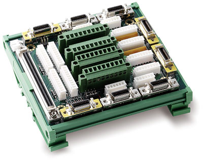
- DIN-100S-01 - 100pin SCSI-II termination board DIN rail w/o cable
- DIN-814M0 - Panel for J2S-A Mitsubishi servo amplifier
- DIN-814M-J3A0 - Panel for J3A Mitsubishi servo amplifier
- DIN-814P-A40 - Panel for MNAS A4 Panasonic servo amplifier
- DIN-814PA0 - Panel for MNAS A Panasonic servo amplifier
- DIN-814Y0 - Panel for Sigma II Yaskawa servo amplifier
- ACL-102100-1 - 100pin SCSI-II cable 1m