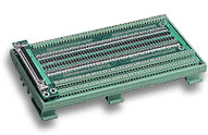
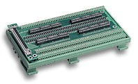
Comprehensive Product Summary: ADLINK TB‑6201‑01 Switch Board and PXI‑7901 Relay Module
### 1. Product Overview
Product Name: TB‑6201‑01 General‑Purpose Switch Termination Board
Article Number: TB‑6201‑01
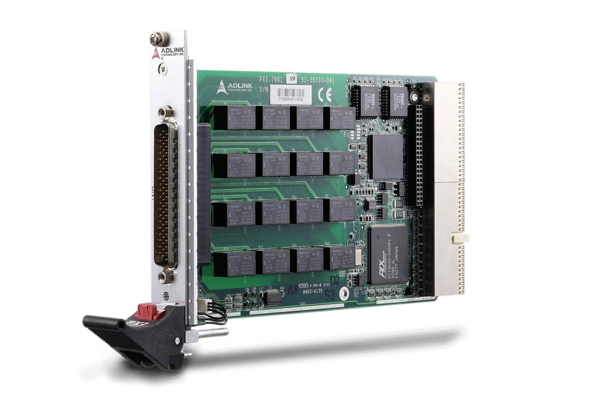
Associated Module: PXI‑7901 16‑Channel General‑Purpose SPDT Relay Module
Manufacturer: ADLINK Technology Inc.
Series: PXI Switch and Measurement Series
Product Type: 62‑Pin D‑Sub Switch Terminal Board (without cable)
Compatible Cable: ACL‑10262 (62‑pin D‑Sub male/female cable, 1 m)
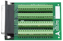
The TB‑6201‑01 is a general‑purpose switch termination board designed for use with ADLINK’s PXI‑7901 relay module. It provides a convenient screw‑terminal interface for signal wiring through a 62‑pin D‑Sub female connector. The board enables easy connection, routing, and testing of relay signals in laboratory, industrial, and automated test environments.
### 2. Key Features
TB‑6201‑01 Terminal Board
- 62‑pin D‑Sub female connector for direct interface with PXI‑7901.
- Screw‑terminal design for secure and flexible signal wiring.
- Supports all relay channels, auxiliary I/O, and trigger lines from the PXI‑7901.
- No cable included (optional ACL‑10262 cable available).
- Compact, durable construction for bench or rack‑mount use.
PXI‑7901 Relay Module
- 16 independent SPDT (Single‑Pole Double‑Throw, 1 Form C) non‑latching relays.
- PXI Specification Rev. 2.2 compliant; CompactPCI (PICMG 2.0 R3.0) and Hot‑Swap (PICMG 2.1 R2.0) compliant.
- 3 A switching and carrying capacity at up to 220 V DC or 250 V AC.
- 125 operations per second with full contact settling.
- Onboard 1 k‑sample scan list for deterministic auto‑scanning.
- Programmable handshaking signals for synchronization with external instruments.
- Safety‑critical design with hardware emergency shutdown and watchdog timer.
- 8 auxiliary 3.3 V/TTL digital I/O channels (5 V tolerant).
- Software‑programmable operation modes and PXI trigger synchronization.
- Fully supported by ADLINK’s ADL‑SWITCH driver for Windows.
### 3. Technical Specifications
TB‑6201‑01 Terminal Board
- Connector Type: 62‑pin D‑Sub female.
- Interface: Screw terminals for each relay contact and auxiliary signal.
- Cable Compatibility: ACL‑10262 (62‑pin D‑Sub male/female, 1 m).
- Material: Industrial‑grade PCB with plated terminals.
- Mounting: Panel or bench‑mount.
- Dimensions/Weight: Compact Eurocard‑compatible footprint (matches PXI‑7901 connector spacing).
PXI‑7901 Relay Module
- Form Factor: 3U Eurocard, PXI/CompactPCI compliant.
- Dimensions: 160 mm (L) × 100 mm (H) (excluding connectors).
- Weight: Approx. 0.5 kg (typical PXI module weight).
- Relay Type: SPDT (1 Form C), non‑latching.
- Number of Channels: 16.
- Max Switching Current: 3 A.
- Max Carrying Current: 3 A.
- Max Switching Voltage: 220 V DC / 250 V AC.
- Max Switching Power: 50 VA / 60 W.
- Contact Resistance: ≤ 150 mΩ.
- Operate/Release Time: ≤ 5 ms each; bounce ≤ 3 ms.
- Mechanical Life: ≥ 10⁸ operations.
- Electrical Life: ≥ 10⁵ operations (0.4 A @ 125 V AC resistive load).
- Operating Temperature: 0 °C – 55 °C.
- Storage Temperature: −20 °C – 70 °C.
- Humidity: 5 % – 85 % RH, non‑condensing.
- Power Requirements: +5 V @ 700 mA, +3.3 V @ 400 mA (all relays ON).
- I/O Connector: 62‑pin D‑Sub male (mates with TB‑6201‑01).
- EMC/EMI Compliance: CE, FCC Class A.
### 4. Functionality
How It Works
The PXI‑7901 relay module provides 16 independent SPDT channels for signal routing, switching, and control. Each relay has three terminals—Common (COM), Normally Closed (NC), and Normally Open (NO). In the de‑energized state, COM connects to NC; when energized, COM connects to NO. The module supports both direct software‑controlled switching and automated scan‑list operation for deterministic signal sequencing.
The TB‑6201‑01 terminal board serves as the physical interface for these relay channels. It allows users to connect external devices, sensors, or circuits to the PXI‑7901 through screw terminals, simplifying wiring and maintenance.
Use Cases and Applications
- Automated Test Equipment (ATE) signal routing.
- Industrial ON/OFF control of motors, fans, heaters, and lights.
- Laboratory automation and measurement switching.
- External high‑power relay driving.
- Limit switch monitoring and contact status sensing.
- Integration with A/D and D/A modules for data acquisition and control systems.
Compatibility
- PXI‑7901 module connects directly to PXI chassis backplane.
- TB‑6201‑01 connects via 62‑pin D‑Sub interface or ACL‑10262 cable.
- Supported operating systems: Windows 2000/XP/Vista/2003.
- Supported programming environments: VB, VC++, BCB, Delphi.
- Recommended software: ADLINK DAQBench and ADL‑SWITCH driver package.
### 5. Components & Accessories
Included Items
- PXI‑7901 Relay Module (when purchased as a kit).
- TB‑6201‑01 Terminal Board (sold separately or as accessory).
- ADLINK Software CD with ADL‑SWITCH drivers and utilities.
- User’s Manual and ADL‑SWITCH User’s Guide.
Optional Accessories
- ACL‑10262 Cable: 62‑pin D‑Sub male/female, 1 m length.
- Additional PXI modules for synchronized multi‑channel switching.
- Mounting hardware for terminal board installation.
Connectors
- PXI‑7901 front panel: 62‑pin D‑Sub male.
- TB‑6201‑01: 62‑pin D‑Sub female with screw terminals.
- PXI backplane: J1/J2 IEC connectors for PXI bus communication.
### 6. Installation & Setup
Requirements
- PXI chassis with available 3U slot.
- Compatible PXI controller or embedded PC.
- Anti‑static handling equipment (mat and wrist strap recommended).
Installation Steps
1. Unpacking: Inspect for shipping damage; handle on grounded anti‑static surface.
2. Module Insertion: Align PXI‑7901 with chassis card guide, slide in until resistance is felt, then engage ejector latch until it clicks. Secure front‑panel screws.
3. Terminal Board Connection: Attach TB‑6201‑01 directly to the module’s 62‑pin connector or via ACL‑10262 cable.
4. Software Setup: Install ADL‑SWITCH driver and utilities from the ADLINK CD. Configure relay channels and scan lists via software.
5. Verification: Use provided test utilities to confirm relay operation and I/O functionality.
Mounting Options
- PXI‑7901 mounts internally in PXI chassis.
- TB‑6201‑01 can be bench‑mounted or panel‑mounted near test fixtures.
Configuration
- Relays can be controlled via direct software commands or pre‑defined scan lists.
- Trigger and synchronization settings are programmable through ADLINK APIs.
- Safety functions (watchdog, emergency shutdown) configurable via Windows API.
### 7. Performance & Capabilities
Switching Performance
- 125 operations per second with full contact settling.
- Debounce time: 8 ms recommended.
- Deterministic scanning via 1 k‑sample onboard scan list.
- Supports both one‑time and cyclic scan modes.
Synchronization & Triggering
- PXI trigger bus and star trigger support for multi‑module synchronization.
- Programmable Trigger In and Scanner Advanced signals for instrument handshaking.
- Adjustable polarity and pulse width for trigger signals.
Auxiliary Digital I/O
- 8 channels, 3.3 V/TTL logic (5 V tolerant).
- Configurable as input, output, or tri‑state.
- Read‑back capability for output verification.
- Dual‑function pins (AUX0–AUX2) for trigger and shutdown control.
Safety & Reliability
- Hardware emergency shutdown input (active‑low, 3.3 V/TTL).
- Programmable watchdog timer (1 ms – 420 s range, 32‑bit counter).
- Relay safety status programmable for fail‑safe operation.
- Hot‑swap support per CompactPCI specification (OS‑dependent).
Limitations
- Non‑latching relays (requires continuous power to maintain energized state).
- Maximum switching voltage limited to 250 V AC or 220 V DC.
- Contact resistance and bounce time may affect high‑speed analog signals.
### 8. Standards & Compliance
- PXI Specification: Rev. 2.2 compliant.
- CompactPCI Compliance: PICMG 2.0 R3.0 (mechanical/electrical), PICMG 2.1 R2.0 (Hot‑Swap).
- EMC/EMI: CE and FCC Class A certified.
- Environmental: Designed for 0 °C – 55 °C operation, 5 % – 85 % RH non‑condensing.
- Safety: Meets industrial control and measurement equipment standards.
- Quality Assurance: Manufactured under ADLINK’s ISO‑certified quality system.
### 9. Additional Information
Warranty
- Standard 2‑year limited warranty from shipment date.
- Covers defects in materials and workmanship.
- Excludes damage from misuse, improper installation, or environmental factors.
- RMA service available via ADLINK website (www.adlinktech.com).
Support & Maintenance
- Technical support via email: service@adlinktech.com.
- Firmware and driver updates available online.
- Maintenance involves periodic inspection of relay contacts and terminal connections.
- Replacement relays and accessories available through ADLINK distributors.
Software & Updates
- ADL‑SWITCH driver package supports Windows 98/ME/NT/2000/XP/Vista/2003.
- Includes test utilities, sample code (VB, VC++, Delphi, BCB), and API documentation.
- DAQBench software recommended for graphical configuration and testing.
- For Linux or VxWorks support, contact ADLINK technical services.
Manufacturer Contact
ADLINK Technology Inc.
9F, No. 166, Jian Yi Road, Chungho City, Taipei 235, Taiwan
Tel: +886‑2‑8226‑5877 Fax: +886‑2‑8226‑5717
Website: [www.adlinktech.com](http://www.adlinktech.com)
### Summary
The ADLINK TB‑6201‑01 terminal board, when paired with the PXI‑7901 16‑channel SPDT relay module, forms a robust and flexible switching solution for PXI‑based test and measurement systems. The PXI‑7901 provides high‑speed, deterministic relay control with advanced synchronization, safety, and digital I/O features, while the TB‑6201‑01 offers a convenient screw‑terminal interface for field wiring. Together, they deliver reliable signal routing, automation, and control capabilities suitable for industrial, laboratory, and ATE environments, fully compliant with PXI and CompactPCI standards and supported by ADLINK’s comprehensive software ecosystem.

.webp)
 SUCHEN SIE DIE PASSENDE
 PXI-7901_Datasheet_en_1.pdf
PDF Catalog
PXI-7901_Datasheet_en_1.pdf
PDF Catalog
 PXI-7901_Manual_4.pdf
Manual
PXI-7901_Manual_4.pdf
Manual