RST-20P
SUCHEN SIE DIE PASSENDE
INDUSTRIELLE LÖSUNG?
Entdecken Sie Embedded-, Kommunikations- und Automatisierungslösungen für Ihre Anwendung.
- USB 2.0 High‑Speed Interface: Provides high‑throughput data transfer and plug‑and‑play connectivity.
- Bus‑Powered Operation: Draws 5 V @ 400 mA directly from the USB port—no external power supply required.
- 8‑Channel Current Input: Measures 0–20 mA signals via built‑in 249.5 Ω precision resistors.
- 16‑bit Resolution: Ensures high‑accuracy analog‑to‑digital conversion.
- Sampling Rate: Up to 250 kS/s (multiplexed, single channel).
- Dual 16‑bit Analog Outputs: Two voltage output channels (±10 V) with 1 MS/s simultaneous update rate.
- Digital I/O: 8 × TTL‑level digital inputs and 4 × TTL‑level digital outputs.
- Programmable Function I/O: Configurable as digital I/O, 32‑bit timer/counter, or PWM generator.
- Triggering: Supports software, external digital, and analog triggers with multiple trigger modes (post, delay, gated, retrigger).
- Removable Screw‑Down Terminals: Two 20‑pin connectors simplify wiring and maintenance.
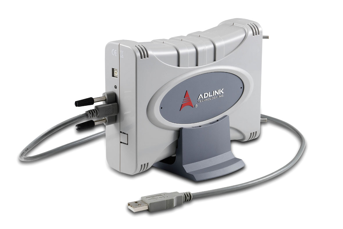
- Lockable USB Cable: Prevents accidental disconnection during operation.
- Multi‑Mount Stand: Supports desktop, DIN‑rail, or wall mounting.
- Software Support: Compatible with ADLINK UD‑DASK, DAQPilot (LabVIEW®), and DAQ‑MTLB (MATLAB®).
- Free Utility: U‑Test software for immediate data acquisition and device testing.
- Operating Systems: Windows XP, Vista, and Windows 7 supported.
- Bus‑Powered Operation: Draws 5 V @ 400 mA directly from the USB port—no external power supply required.
- 8‑Channel Current Input: Measures 0–20 mA signals via built‑in 249.5 Ω precision resistors.
- 16‑bit Resolution: Ensures high‑accuracy analog‑to‑digital conversion.
- Sampling Rate: Up to 250 kS/s (multiplexed, single channel).
- Dual 16‑bit Analog Outputs: Two voltage output channels (±10 V) with 1 MS/s simultaneous update rate.
- Digital I/O: 8 × TTL‑level digital inputs and 4 × TTL‑level digital outputs.
- Programmable Function I/O: Configurable as digital I/O, 32‑bit timer/counter, or PWM generator.
- Triggering: Supports software, external digital, and analog triggers with multiple trigger modes (post, delay, gated, retrigger).
- Removable Screw‑Down Terminals: Two 20‑pin connectors simplify wiring and maintenance.
- Lockable USB Cable: Prevents accidental disconnection during operation.
- Multi‑Mount Stand: Supports desktop, DIN‑rail, or wall mounting.
- Software Support: Compatible with ADLINK UD‑DASK, DAQPilot (LabVIEW®), and DAQ‑MTLB (MATLAB®).
- Free Utility: U‑Test software for immediate data acquisition and device testing.
- Operating Systems: Windows XP, Vista, and Windows 7 supported.
Comprehensive Product Summary – ADLINK USB‑1903 Current Input Data Acquisition Module
### 1. Product Overview
Product Name: USB‑1903
Model: USB‑1903
Series: USB‑1900 Series – 16‑bit, 250 kS/s Multi‑Function USB DAQ Modules
Article Number: USB‑1903
Manufacturer: ADLINK Technology Inc.
Part Number: 50‑1Z084‑2000
Revision: Manual Rev. 2.00 (August 31, 2011)
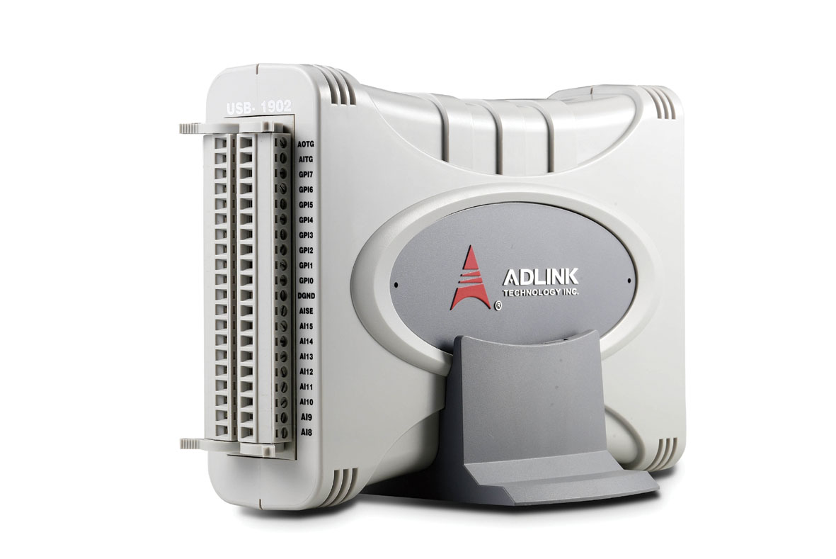
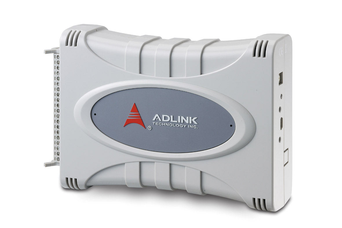
The ADLINK USB‑1903 is a high‑performance, USB 2.0‑based, multi‑function data acquisition (DAQ) module designed for direct current‑signal measurement. It belongs to the USB‑1900 Series, which also includes the USB‑1901 (voltage input) and USB‑1902 (multi‑function voltage input/output) models. The USB‑1903 distinguishes itself by integrating precision current‑to‑voltage conversion resistors, enabling direct measurement of 0–20 mA current signals without external shunt resistors. It is fully USB‑bus powered, compact, and engineered for laboratory, industrial, and automation environments requiring reliable mixed‑signal data acquisition.
### 2. Key Features
- USB 2.0 High‑Speed Interface: Provides high‑throughput data transfer and plug‑and‑play connectivity.
- Bus‑Powered Operation: Draws 5 V @ 400 mA directly from the USB port—no external power supply required.
- 8‑Channel Current Input: Measures 0–20 mA signals via built‑in 249.5 Ω precision resistors.
- 16‑bit Resolution: Ensures high‑accuracy analog‑to‑digital conversion.
- Sampling Rate: Up to 250 kS/s (multiplexed, single channel).
- Dual 16‑bit Analog Outputs: Two voltage output channels (±10 V) with 1 MS/s simultaneous update rate.
- Digital I/O: 8 × TTL‑level digital inputs and 4 × TTL‑level digital outputs.
- Programmable Function I/O: Configurable as digital I/O, 32‑bit timer/counter, or PWM generator.
- Triggering: Supports software, external digital, and analog triggers with multiple trigger modes (post, delay, gated, retrigger).
- Removable Screw‑Down Terminals: Two 20‑pin connectors simplify wiring and maintenance.
- Lockable USB Cable: Prevents accidental disconnection during operation.
- Multi‑Mount Stand: Supports desktop, DIN‑rail, or wall mounting.
- Software Support: Compatible with ADLINK UD‑DASK, DAQPilot (LabVIEW®), and DAQ‑MTLB (MATLAB®).
- Free Utility: U‑Test software for immediate data acquisition and device testing.
- Operating Systems: Windows XP, Vista, and Windows 7 supported.
### 3. Technical Specifications
Analog Input (AI):
- Channels: 8 differential current inputs
- Resolution: 16 bits
- Sampling Rate: 250 kS/s (single channel, multiplexed)
- Input Range: 0 – 20 mA
- Input Coupling: DC
- Input Impedance: 249.5 Ω precision resistor
- Overvoltage Protection: ±24 V continuous
- Offset Error: ±0.01 mA (typical)
- Gain Error: ±0.05 % FSR (typical)
- Common‑Mode Voltage Range: ±24 V
- FIFO Buffer: 4 k samples
- Trigger Sources: Software, external digital, or analog
- Trigger Modes: Post, delay, retrigger, gated
- Data Transfer: Programmed I/O or continuous USB bulk transfer
Analog Output (AO):
- Channels: 2 voltage outputs
- Resolution: 16 bits
- Update Rate: 1 MS/s (simultaneous)
- Output Range: ±10 V
- Output Drive: ±5 mA
- Slew Rate: 20 V/µs
- Settling Time: 2.5 µs (0.1 % FS)
- INL/DNL: ≤ 1 LSB
- FIFO Size: 10 k samples (shared by 2 channels)
Digital I/O:
- 8 × DI / 4 × DO, TTL‑level (3.3 V / 5 V compatible)
- Logic Low: ≤ 0.8 V; Logic High: ≥ 2.0 V
- Output Low: ≤ 0.5 V @ 10 mA; Output High: ≥ 2.6 V @ 10 mA
Timer/Counter:
- Two 32‑bit general‑purpose counters
- Base Clock: 80 MHz internal / 10 MHz external
- PWM Output: 0.01 Hz – 5 MHz, 1–99 % duty cycle
Interface & Power:
- Interface: USB 2.0 High‑Speed (Mini‑B connector)
- Power: 5 V @ 400 mA (USB bus powered)
Physical:
- Dimensions: 115 mm (W) × 150 mm (D) × 40 mm (H) (4.5 × 5.91 × 1.57 in.)
- Weight: Approx. 0.5 kg (module only)
- Connectors: Two 20‑pin removable screw terminals
Environmental:
- Operating Temperature: 0 – 55 °C
- Storage Temperature: –20 – 70 °C
- Humidity: 5 – 95 % RH, non‑condensing
### 4. Functionality
The USB‑1903 operates as a precision current‑input DAQ device. Each of its eight differential input channels converts current signals (0–20 mA) into voltage using onboard 249.5 Ω resistors. The resulting voltage is digitized by a 16‑bit ADC (AD7610 or equivalent). The module supports simultaneous analog input, analog output, and digital I/O operations.
Typical Applications:
- Industrial process monitoring (4–20 mA sensors, transducers)
- Factory automation and control systems
- Laboratory instrumentation and research
- Biomedical and biotech measurement systems
- Automotive and mechanical testing
- Waveform generation and signal simulation
Compatibility:
- Fully compatible with Windows‑based DAQ software environments.
- Supported by ADLINK’s UD‑DASK driver library, DAQPilot SDK for LabVIEW®, and DAQ‑MTLB for MATLAB®.
- U‑Test utility allows immediate verification of analog and digital functions without programming.
### 5. Components & Accessories
Included Items:
- USB‑1903 module
- Multi‑function stand (desktop, rail, wall mount)
- Two 20‑pin removable screw‑down terminal blocks (RST‑20P)
- Lockable 2 m USB Type‑A to Mini‑B cable (USB‑2M‑L)
- Rail‑mount kit
- ADLINK All‑in‑One CD (drivers, utilities, manuals)
- Printed user manual
Optional Accessories:
- Additional RST‑20P terminal blocks
- Extended‑length lockable USB cables
- Calibration service (for current input accuracy verification)
### 6. Installation & Setup
Requirements:
- Windows XP/Vista/7 operating system
- One available USB 2.0 port capable of supplying 400 mA @ 5 V
- Installation of ADLINK UD‑DASK or DAQPilot drivers prior to connection
Setup Procedure:
1. Install the appropriate driver package from the ADLINK All‑in‑One CD.
2. Connect the USB‑1903 to a USB 2.0 port using the supplied lockable cable.
3. Wait for firmware loading (LED changes from amber to green).
4. Verify device recognition in Windows Device Manager.
5. Configure device ID (rotary switch 1–8) to avoid conflicts when multiple modules are used.
6. Launch U‑Test or your preferred DAQ software to begin operation.
Mounting Options:
- Desktop: Place module in stand for stable operation.
- DIN‑Rail: Attach stand to rail‑mount kit for industrial panels.
- Wall Mount: Secure stand using four 3.4 mm screws through mounting holes.
### 7. Performance & Capabilities
Analog Input Performance:
- 16‑bit resolution with 14.5 ENOB typical
- Sampling rate up to 250 kS/s
- Offset error ±0.01 mA; gain error ±0.05 % FSR
- Common‑mode rejection up to ±24 V
- Continuous ±24 V overvoltage protection
Analog Output Performance:
- 16‑bit resolution, ±10 V range
- 1 MS/s update rate (simultaneous dual‑channel)
- Slew rate 20 V/µs; settling 2.5 µs
- Output drive ±5 mA
Digital I/O & Timing:
- 8 DI / 4 DO TTL lines for control and monitoring
- Two 32‑bit counters with 80 MHz internal clock
- Four PWM outputs (0.01 Hz – 5 MHz)
Limitations:
- USB bus power limits total current draw to 400 mA.
- Auto‑calibration not supported (requires external calibration source).
- Maximum sampling rate shared across multiplexed channels.
### 8. Standards & Compliance
- USB 2.0 High‑Speed compliant
- RoHS (Restriction of Hazardous Substances) compliant
- WEEE (Waste Electrical and Electronic Equipment) directive compliant
- CE and FCC conformity (industrial EMC standards)
- Designed and manufactured under ADLINK’s ISO 9001 quality system
- Environmental responsibility: low‑impact materials and recyclable packaging
### 9. Additional Information
Calibration:
- Factory‑calibrated before shipment; constants stored in onboard EEPROM.
- User calibration supported via software utility (external precision current source required).
- Factory constants can be restored at any time.
- Recommended warm‑up: 15 minutes before calibration.
Warranty & Support:
- Standard ADLINK limited warranty (typically 2 years; region‑dependent).
- Worldwide technical support via ADLINK offices in Taiwan, USA, Europe, China, Japan, Korea, Singapore, and India.
- Email support: service@adlinktech.com
- Website: [www.adlinktech.com](http://www.adlinktech.com)
Maintenance:
- Keep connectors clean and dry.
- Avoid exposure to excessive humidity or vibration.
- Disconnect USB cable before cleaning or calibration.
- Periodic recalibration recommended for precision applications.
Software Updates:
- Latest drivers and utilities available from ADLINK’s website.
- DAQPilot ≥ v2.3.0.712 required for USB‑1900 Series compatibility.
- U‑Test utility provides firmware update and diagnostic functions.
### Summary
The ADLINK USB‑1903 is a compact, high‑precision, USB‑powered data acquisition module optimized for current‑signal measurement. With eight 16‑bit differential current inputs, dual 16‑bit analog outputs, and integrated digital I/O and timing functions, it delivers a versatile platform for laboratory, industrial, and automation tasks. Its robust design—featuring removable screw terminals, lockable USB connectivity, and multi‑mount capability—ensures reliability in demanding environments. Comprehensive driver and software support, combined with ADLINK’s global service network, make the USB‑1903 an efficient and cost‑effective solution for mixed‑signal data acquisition and control applications.

### 1. Product Overview
Product Name: USB‑1903
Model: USB‑1903
Series: USB‑1900 Series – 16‑bit, 250 kS/s Multi‑Function USB DAQ Modules
Article Number: USB‑1903
Manufacturer: ADLINK Technology Inc.
Part Number: 50‑1Z084‑2000
Revision: Manual Rev. 2.00 (August 31, 2011)
The ADLINK USB‑1903 is a high‑performance, USB 2.0‑based, multi‑function data acquisition (DAQ) module designed for direct current‑signal measurement. It belongs to the USB‑1900 Series, which also includes the USB‑1901 (voltage input) and USB‑1902 (multi‑function voltage input/output) models. The USB‑1903 distinguishes itself by integrating precision current‑to‑voltage conversion resistors, enabling direct measurement of 0–20 mA current signals without external shunt resistors. It is fully USB‑bus powered, compact, and engineered for laboratory, industrial, and automation environments requiring reliable mixed‑signal data acquisition.
### 2. Key Features
- USB 2.0 High‑Speed Interface: Provides high‑throughput data transfer and plug‑and‑play connectivity.
- Bus‑Powered Operation: Draws 5 V @ 400 mA directly from the USB port—no external power supply required.
- 8‑Channel Current Input: Measures 0–20 mA signals via built‑in 249.5 Ω precision resistors.
- 16‑bit Resolution: Ensures high‑accuracy analog‑to‑digital conversion.
- Sampling Rate: Up to 250 kS/s (multiplexed, single channel).
- Dual 16‑bit Analog Outputs: Two voltage output channels (±10 V) with 1 MS/s simultaneous update rate.
- Digital I/O: 8 × TTL‑level digital inputs and 4 × TTL‑level digital outputs.
- Programmable Function I/O: Configurable as digital I/O, 32‑bit timer/counter, or PWM generator.
- Triggering: Supports software, external digital, and analog triggers with multiple trigger modes (post, delay, gated, retrigger).
- Removable Screw‑Down Terminals: Two 20‑pin connectors simplify wiring and maintenance.
- Lockable USB Cable: Prevents accidental disconnection during operation.
- Multi‑Mount Stand: Supports desktop, DIN‑rail, or wall mounting.
- Software Support: Compatible with ADLINK UD‑DASK, DAQPilot (LabVIEW®), and DAQ‑MTLB (MATLAB®).
- Free Utility: U‑Test software for immediate data acquisition and device testing.
- Operating Systems: Windows XP, Vista, and Windows 7 supported.
### 3. Technical Specifications
Analog Input (AI):
- Channels: 8 differential current inputs
- Resolution: 16 bits
- Sampling Rate: 250 kS/s (single channel, multiplexed)
- Input Range: 0 – 20 mA
- Input Coupling: DC
- Input Impedance: 249.5 Ω precision resistor
- Overvoltage Protection: ±24 V continuous
- Offset Error: ±0.01 mA (typical)
- Gain Error: ±0.05 % FSR (typical)
- Common‑Mode Voltage Range: ±24 V
- FIFO Buffer: 4 k samples
- Trigger Sources: Software, external digital, or analog
- Trigger Modes: Post, delay, retrigger, gated
- Data Transfer: Programmed I/O or continuous USB bulk transfer
Analog Output (AO):
- Channels: 2 voltage outputs
- Resolution: 16 bits
- Update Rate: 1 MS/s (simultaneous)
- Output Range: ±10 V
- Output Drive: ±5 mA
- Slew Rate: 20 V/µs
- Settling Time: 2.5 µs (0.1 % FS)
- INL/DNL: ≤ 1 LSB
- FIFO Size: 10 k samples (shared by 2 channels)
Digital I/O:
- 8 × DI / 4 × DO, TTL‑level (3.3 V / 5 V compatible)
- Logic Low: ≤ 0.8 V; Logic High: ≥ 2.0 V
- Output Low: ≤ 0.5 V @ 10 mA; Output High: ≥ 2.6 V @ 10 mA
Timer/Counter:
- Two 32‑bit general‑purpose counters
- Base Clock: 80 MHz internal / 10 MHz external
- PWM Output: 0.01 Hz – 5 MHz, 1–99 % duty cycle
Interface & Power:
- Interface: USB 2.0 High‑Speed (Mini‑B connector)
- Power: 5 V @ 400 mA (USB bus powered)
Physical:
- Dimensions: 115 mm (W) × 150 mm (D) × 40 mm (H) (4.5 × 5.91 × 1.57 in.)
- Weight: Approx. 0.5 kg (module only)
- Connectors: Two 20‑pin removable screw terminals
Environmental:
- Operating Temperature: 0 – 55 °C
- Storage Temperature: –20 – 70 °C
- Humidity: 5 – 95 % RH, non‑condensing
### 4. Functionality
The USB‑1903 operates as a precision current‑input DAQ device. Each of its eight differential input channels converts current signals (0–20 mA) into voltage using onboard 249.5 Ω resistors. The resulting voltage is digitized by a 16‑bit ADC (AD7610 or equivalent). The module supports simultaneous analog input, analog output, and digital I/O operations.
Typical Applications:
- Industrial process monitoring (4–20 mA sensors, transducers)
- Factory automation and control systems
- Laboratory instrumentation and research
- Biomedical and biotech measurement systems
- Automotive and mechanical testing
- Waveform generation and signal simulation
Compatibility:
- Fully compatible with Windows‑based DAQ software environments.
- Supported by ADLINK’s UD‑DASK driver library, DAQPilot SDK for LabVIEW®, and DAQ‑MTLB for MATLAB®.
- U‑Test utility allows immediate verification of analog and digital functions without programming.
### 5. Components & Accessories
Included Items:
- USB‑1903 module
- Multi‑function stand (desktop, rail, wall mount)
- Two 20‑pin removable screw‑down terminal blocks (RST‑20P)
- Lockable 2 m USB Type‑A to Mini‑B cable (USB‑2M‑L)
- Rail‑mount kit
- ADLINK All‑in‑One CD (drivers, utilities, manuals)
- Printed user manual
Optional Accessories:
- Additional RST‑20P terminal blocks
- Extended‑length lockable USB cables
- Calibration service (for current input accuracy verification)
### 6. Installation & Setup
Requirements:
- Windows XP/Vista/7 operating system
- One available USB 2.0 port capable of supplying 400 mA @ 5 V
- Installation of ADLINK UD‑DASK or DAQPilot drivers prior to connection
Setup Procedure:
1. Install the appropriate driver package from the ADLINK All‑in‑One CD.
2. Connect the USB‑1903 to a USB 2.0 port using the supplied lockable cable.
3. Wait for firmware loading (LED changes from amber to green).
4. Verify device recognition in Windows Device Manager.
5. Configure device ID (rotary switch 1–8) to avoid conflicts when multiple modules are used.
6. Launch U‑Test or your preferred DAQ software to begin operation.
Mounting Options:
- Desktop: Place module in stand for stable operation.
- DIN‑Rail: Attach stand to rail‑mount kit for industrial panels.
- Wall Mount: Secure stand using four 3.4 mm screws through mounting holes.
### 7. Performance & Capabilities
Analog Input Performance:
- 16‑bit resolution with 14.5 ENOB typical
- Sampling rate up to 250 kS/s
- Offset error ±0.01 mA; gain error ±0.05 % FSR
- Common‑mode rejection up to ±24 V
- Continuous ±24 V overvoltage protection
Analog Output Performance:
- 16‑bit resolution, ±10 V range
- 1 MS/s update rate (simultaneous dual‑channel)
- Slew rate 20 V/µs; settling 2.5 µs
- Output drive ±5 mA
Digital I/O & Timing:
- 8 DI / 4 DO TTL lines for control and monitoring
- Two 32‑bit counters with 80 MHz internal clock
- Four PWM outputs (0.01 Hz – 5 MHz)
Limitations:
- USB bus power limits total current draw to 400 mA.
- Auto‑calibration not supported (requires external calibration source).
- Maximum sampling rate shared across multiplexed channels.
### 8. Standards & Compliance
- USB 2.0 High‑Speed compliant
- RoHS (Restriction of Hazardous Substances) compliant
- WEEE (Waste Electrical and Electronic Equipment) directive compliant
- CE and FCC conformity (industrial EMC standards)
- Designed and manufactured under ADLINK’s ISO 9001 quality system
- Environmental responsibility: low‑impact materials and recyclable packaging
### 9. Additional Information
Calibration:
- Factory‑calibrated before shipment; constants stored in onboard EEPROM.
- User calibration supported via software utility (external precision current source required).
- Factory constants can be restored at any time.
- Recommended warm‑up: 15 minutes before calibration.
Warranty & Support:
- Standard ADLINK limited warranty (typically 2 years; region‑dependent).
- Worldwide technical support via ADLINK offices in Taiwan, USA, Europe, China, Japan, Korea, Singapore, and India.
- Email support: service@adlinktech.com
- Website: [www.adlinktech.com](http://www.adlinktech.com)
Maintenance:
- Keep connectors clean and dry.
- Avoid exposure to excessive humidity or vibration.
- Disconnect USB cable before cleaning or calibration.
- Periodic recalibration recommended for precision applications.
Software Updates:
- Latest drivers and utilities available from ADLINK’s website.
- DAQPilot ≥ v2.3.0.712 required for USB‑1900 Series compatibility.
- U‑Test utility provides firmware update and diagnostic functions.
### Summary
The ADLINK USB‑1903 is a compact, high‑precision, USB‑powered data acquisition module optimized for current‑signal measurement. With eight 16‑bit differential current inputs, dual 16‑bit analog outputs, and integrated digital I/O and timing functions, it delivers a versatile platform for laboratory, industrial, and automation tasks. Its robust design—featuring removable screw terminals, lockable USB connectivity, and multi‑mount capability—ensures reliability in demanding environments. Comprehensive driver and software support, combined with ADLINK’s global service network, make the USB‑1903 an efficient and cost‑effective solution for mixed‑signal data acquisition and control applications.
-
USB-1901+1902+1903_Datasheet_en_1.pdf
PDF Catalog
-
USB-1900_series_datasheet.pdf
PDF Catalog