LOOKING FOR THE RIGHT
INDUSTRIAL SOLUTION?
Discover embedded, communication and automation solutions tailored to your application.
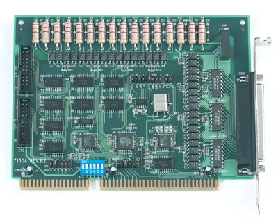
- 32 total isolated channels: 16 opto‑isolated digital inputs and 16 opto‑isolated digital outputs.
- Additional 32 non‑isolated TTL/DTL channels: 16 digital inputs and 16 digital outputs for direct logic‑level interfacing.
- High isolation protection: 2,500 VDC isolation between field and logic sides for both input and output channels.
- Wide input voltage range: Accepts 5 V to 24 V DC (non‑polarity photo‑coupler inputs).
- Open‑collector outputs: Supports 5 V to 40 V DC external voltage with up to 500 mA sink current per channel (single active channel).
- Dual interrupt capability:
- External interrupt from digital input channels (IRQ3–7).
- Internal interrupt from onboard timer pacer (IRQ9–12, 15).
- Integrated 8254 programmable counter/timer:
- Three 16‑bit counters.
- Two cascaded counters for timer pacer generation.
- One free counter for user applications.
- Base frequency: 2 MHz.
- Flexible software support: Compatible with DOS, Windows 95/98/NT, and LabVIEW via optional libraries (ACLS‑DLL1, ACLS‑LVIEW).
- Compact half‑size ISA form factor: 163 mm × 123 mm PCB.
- Standard connectors:
- One DB‑37 female connector for isolated I/O.
- Two 20‑pin headers for TTL I/O.
- Industrial‑grade reliability: Designed for 0 °C – 60 °C operation, 5 – 95 % non‑condensing humidity.
- Low power consumption: +5 V @ 360 mA typical.
- Additional 32 non‑isolated TTL/DTL channels: 16 digital inputs and 16 digital outputs for direct logic‑level interfacing.
- High isolation protection: 2,500 VDC isolation between field and logic sides for both input and output channels.
- Wide input voltage range: Accepts 5 V to 24 V DC (non‑polarity photo‑coupler inputs).
- Open‑collector outputs: Supports 5 V to 40 V DC external voltage with up to 500 mA sink current per channel (single active channel).
- Dual interrupt capability:
- External interrupt from digital input channels (IRQ3–7).
- Internal interrupt from onboard timer pacer (IRQ9–12, 15).
- Integrated 8254 programmable counter/timer:
- Three 16‑bit counters.
- Two cascaded counters for timer pacer generation.
- One free counter for user applications.
- Base frequency: 2 MHz.
- Flexible software support: Compatible with DOS, Windows 95/98/NT, and LabVIEW via optional libraries (ACLS‑DLL1, ACLS‑LVIEW).
- Compact half‑size ISA form factor: 163 mm × 123 mm PCB.
- Standard connectors:
- One DB‑37 female connector for isolated I/O.
- Two 20‑pin headers for TTL I/O.
- Industrial‑grade reliability: Designed for 0 °C – 60 °C operation, 5 – 95 % non‑condensing humidity.
- Low power consumption: +5 V @ 360 mA typical.
Comprehensive Product Summary – ADLINK NuDAQ ACL‑7130 Isolated Digital I/O Card
### 1. Product Overview
Product Name: ACL‑7130
Model: ACL‑7130
Series: NuDAQ ISA‑Bus Data Acquisition Series
Article Number: ACL‑7130
Manufacturer: ADLINK Technology Inc.
Manufacturer Address: 9F, No. 166, Jian Yi Road, Chungho City, Taipei 235, Taiwan, R.O.C.
Website: [www.adlink.com.tw](http://www.adlink.com.tw)
Support Contacts:
- Sales & Service: service@adlink.com.tw
- Technical Support (NuDAQ): nudaq@adlink.com.tw
- Software Support: sw@adlink.com.tw
- Telephone: +886‑2‑82265877
- Fax: +886‑2‑82265717
The ADLINK ACL‑7130 is an ISA‑bus isolated digital input/output card designed for industrial and laboratory automation systems. It provides a combination of 16 optically isolated digital inputs, 16 optically isolated digital outputs, and 16 non‑isolated TTL/DTL‑compatible digital I/O channels, offering flexible interfacing between industrial control signals and PC‑based systems. The card integrates an Intel 8254 programmable timer/counter, dual interrupt channels, and a robust isolation design for reliable operation in electrically noisy environments.
### 2. Key Features
- 32 total isolated channels: 16 opto‑isolated digital inputs and 16 opto‑isolated digital outputs.
- Additional 32 non‑isolated TTL/DTL channels: 16 digital inputs and 16 digital outputs for direct logic‑level interfacing.
- High isolation protection: 2,500 VDC isolation between field and logic sides for both input and output channels.
- Wide input voltage range: Accepts 5 V to 24 V DC (non‑polarity photo‑coupler inputs).
- Open‑collector outputs: Supports 5 V to 40 V DC external voltage with up to 500 mA sink current per channel (single active channel).
- Dual interrupt capability:
- External interrupt from digital input channels (IRQ3–7).
- Internal interrupt from onboard timer pacer (IRQ9–12, 15).
- Integrated 8254 programmable counter/timer:
- Three 16‑bit counters.
- Two cascaded counters for timer pacer generation.
- One free counter for user applications.
- Base frequency: 2 MHz.
- Flexible software support: Compatible with DOS, Windows 95/98/NT, and LabVIEW via optional libraries (ACLS‑DLL1, ACLS‑LVIEW).
- Compact half‑size ISA form factor: 163 mm × 123 mm PCB.
- Standard connectors:
- One DB‑37 female connector for isolated I/O.
- Two 20‑pin headers for TTL I/O.
- Industrial‑grade reliability: Designed for 0 °C – 60 °C operation, 5 – 95 % non‑condensing humidity.
- Low power consumption: +5 V @ 360 mA typical.
### 3. Technical Specifications
General:
- Bus Interface: ISA (AT‑Bus)
- I/O Port Address Range: Hex 200 – 3F8 (8 bytes used)
- Interrupt Levels:
- External: IRQ 3, 4, 5, 6, 7
- Internal (Timer): IRQ 9, 10, 11, 12, 15
- Power Requirement: +5 V DC @ 360 mA (typical)
- Operating Temperature: 0 °C – 60 °C
- Storage Temperature: −20 °C – 80 °C
- Humidity: 5 – 95 % RH, non‑condensing
- Dimensions: 163 mm (L) × 123 mm (W)
- Form Factor: Compact / Half‑size ISA card
Isolated Digital Inputs:
- Channels: 16
- Input Type: Non‑polarity photo‑coupler
- Input Voltage Range: 0 – 24 V DC
- Logic H: 3 – 24 V
- Logic L: 0 – 2.4 V
- Input Resistance: 1.2 kΩ @ 1 W (470 Ω optional version)
- Isolation Voltage: 2,500 V DC
- Maximum Throughput: 10 kHz
Isolated Digital Outputs:
- Channels: 16
- Output Type: Open‑collector transistor (TD62003 array)
- Output Voltage Range: 5 V – 40 V DC
- Sink Current:
- 500 mA max per channel (single active transistor)
- 347 mA max per channel (all channels active, 10 % duty)
- Isolation Voltage: 2,500 V DC
- Maximum Throughput: 10 kHz
Non‑Isolated Digital Inputs:
- Channels: 16
- Logic Low Voltage: −0.5 V (min) – 0.8 V (max)
- Logic High Voltage: 2.0 V (min) – 5.0 V (max)
- Input Loading Current: ≤ 0.2 mA @ 0.4 V
Non‑Isolated Digital Outputs:
- Channels: 16
- Logic Low (Sink): ≤ 0.5 V @ 24 mA
- Logic High (Source): ≤ 0.4 V @ 12 mA
- Compatibility: TTL/DTL logic levels
Programmable Counter/Timer (Intel 8254):
- Counters: 3 × 16‑bit
- Base Frequency: 2 MHz
- Counter 0: User‑programmable (CLK and GATE available via JP5)
- Counters 1 & 2: Cascaded for timer pacer generation
- Output Connector: JP5 (6‑pin header)
- Pacer Rate Formula: 2 MHz / (C1 × C2)
- Frequency Range: 2 MHz (max) to ≈ 0.00047 Hz (min)
### 4. Functionality
The ACL‑7130 functions as a digital interface card bridging PC‑based control systems with external industrial devices. It supports both isolated and non‑isolated digital I/O operations, allowing safe connection to sensors, actuators, relays, and logic circuits.
Operation Principles:
- Isolated Inputs: Each input channel uses a photo‑coupler to detect external DC/AC signals (5–24 V). The opto‑isolation protects the PC from voltage spikes and ground loops.
- Isolated Outputs: Open‑collector transistor outputs switch external loads (5–40 V DC). External power must be supplied to the output side (VDD pin).
- Non‑Isolated I/O: TTL/DTL‑compatible channels directly interface with logic‑level devices or daughterboards (e.g., ACLD‑9182, ACLD‑9185).
- Interrupt Handling:
- External interrupts can be triggered by selected input channels (IDI0, IDI1, DI0, DI1).
- Internal timer interrupts are generated by the cascaded 8254 counters.
- Both interrupt sources can operate simultaneously on separate IRQ lines.
- Timer/Counter Functions: The onboard 8254 supports event counting, frequency generation, watchdog timing, and programmable interval timing.
- Software Control: All I/O operations are accessed via 8‑bit port commands. The card can be programmed in assembly, BASIC, C/C++, or through ADLINK’s DLL libraries for Windows and LabVIEW environments.
Typical Applications:
- Industrial process control and automation
- Laboratory data acquisition
- Programmable logic control (PLC) interfacing
- Event counting and frequency measurement
- Watchdog timer and trigger signal monitoring
- Machine status monitoring and alarm systems
Compatibility:
- Hardware: Standard ISA‑bus PCs
- Software: DOS, Windows 95/98/NT, LabVIEW (via ACLS‑LVIEW)
- Programming Languages: Assembly, BASIC, C, Pascal, Visual Basic, Delphi, C++
### 5. Components & Accessories
Package Contents:
- 1 × ACL‑7130 Isolated Digital I/O Card
- 1 × ADLINK Product CD (includes DOS library, utilities, and documentation)
- 1 × User’s Manual
Connectors:
- CN3 (DB‑37 female): Isolated digital I/O connector
- 16 × IDI (inputs), 16 × IDO (outputs), VDD, EIGND, EOGND
- CN1 (20‑pin header): Non‑isolated digital outputs (DO 0–15)
- CN2 (20‑pin header): Non‑isolated digital inputs (DI 0–15)
- JP5 (6‑pin header): Counter 0 signals (CLK0, GATE0, OUT0, GATE1, OUT1/Pacer, GND)
- JP1/JP2: IRQ selection jumpers (external/internal)
- JP3/JP6: IRQ source selection jumpers
- JP4: IRQ polarity (rising/falling edge)
- SW1: 6‑position DIP switch for base address configuration
Optional Accessories:
- ACLD‑9182 / ACLD‑9185: Daughterboards for TTL I/O expansion
- ACLS‑DLL1: Windows 95/98/NT DLL software library
- ACLS‑LVIEW: LabVIEW driver package
### 6. Installation & Setup
Pre‑installation Precautions:
- Handle the card on a grounded anti‑static mat.
- Wear an anti‑static wrist strap connected to the same ground.
- Inspect for shipping damage before installation.
Installation Steps:
1. Power off the PC and remove the cover.
2. Insert the ACL‑7130 into an available ISA slot.
3. Secure the card with a screw.
4. Connect external devices to the DB‑37 or 20‑pin headers as required.
5. Configure base address and IRQ settings via DIP switch SW1 and jumpers JP1/JP2.
6. Install the software library from the ADLINK CD:
- Navigate to `X:\NuDAQISA\7130`
- Run `SETUP` to install DOS utilities and drivers.
Base Address Configuration:
- Selectable via 6‑bit DIP switch SW1 (A8–A3 lines).
- Default base address: Hex 300.
- Valid range: Hex 200 – 3FF (8 bytes).
- Ensure no conflict with other add‑on cards.
Interrupt Configuration:
- JP1: Lower IRQ (external signals) – selectable IRQ3–7.
- JP2: Higher IRQ (timer pacer) – selectable IRQ9–12, 15.
- JP3/JP6: Select interrupt source (IDI0, IDI1, DI0, DI1, OUT1).
- JP4: Select trigger polarity (rising or falling edge).
Counter Configuration:
- JP5: Provides access to Counter 0 signals for external clocking or gating.
- Pacer Rate Calculation:
`Rate = 2 MHz / (C1 × C2)`
### 7. Performance & Capabilities
Speed and Throughput:
- Isolated I/O maximum switching rate: 10 kHz.
- TTL I/O switching limited by ISA bus speed and software latency.
- Timer pacer frequency range: 2 MHz (max) to sub‑Hz (programmable).
Capacity:
- 32 isolated channels + 32 non‑isolated channels = 64 total I/O lines.
- 3 × 16‑bit counters (one free, two cascaded).
Efficiency:
- Low power draw (1.8 W typical).
- Hardware interrupt support reduces CPU polling overhead.
- Opto‑isolation ensures signal integrity in high‑noise environments.
Limitations:
- ISA‑bus interface (requires legacy PC or industrial backplane).
- No onboard analog I/O.
- External power supply required for isolated outputs (5–40 V DC).
### 8. Standards & Compliance
- Electrical Isolation: 2,500 V DC (input/output to logic).
- Bus Compatibility: Fully compliant with ISA (AT‑Bus) specifications.
- Logic Compatibility: TTL/DTL levels for non‑isolated I/O.
- Component Standards: Utilizes Intel/NEC 8254 programmable timer.
- Environmental: Designed for industrial temperature and humidity ranges.
- Safety & EMC: Meets general industrial electronic equipment design practices (no specific CE/FCC data provided in manual).
### 9. Additional Information
Software Support:
- DOS Library: Included on ADLINK CD for low‑level programming.
- Windows DLL (ACLS‑DLL1): Provides API for Visual Basic, Visual C++, Delphi.
- LabVIEW Driver (ACLS‑LVIEW): Provides VIs for integration with National Instruments LabVIEW.
- Programming Access: 8‑bit I/O port commands; compatible with assembly, BASIC, C, and Pascal.
Maintenance:
- Keep connectors clean and free of dust.
- Avoid exposure to excessive humidity or corrosive environments.
- Verify jumper and DIP switch settings after long‑term storage or transport.
Warranty:
- Duration: 1 year from original purchase date.
- Coverage: Defects in materials and workmanship.
- Exclusions:
- Damage from misuse, modification, or operation beyond specifications.
- Units with removed or altered serial numbers.
- Consequential damages are excluded; liability limited to product cost.
- Service Procedure:
- Obtain RMA authorization from ADLINK.
- Return product prepaid and insured.
- Include proof of purchase for warranty validation.
Support & Updates:
- Firmware and software updates available via ADLINK website.
- Technical assistance provided through regional distributors or direct email support.
### Summary
The ADLINK NuDAQ ACL‑7130 is a robust, industrial‑grade isolated digital I/O card for ISA‑bus systems, combining high‑voltage isolation, flexible interrupt handling, and integrated timing functions. With 16 isolated inputs, 16 isolated outputs, and 16 TTL I/O channels, it supports a wide range of automation and control applications. The inclusion of an 8254 programmable counter, dual interrupt lines, and comprehensive software support makes it suitable for both low‑level hardware control and high‑level Windows‑based data acquisition systems. Its durable design, 2.5 kV isolation, and 0–60 °C operating range ensure reliable performance in demanding industrial environments.
### 1. Product Overview
Product Name: ACL‑7130
Model: ACL‑7130
Series: NuDAQ ISA‑Bus Data Acquisition Series
Article Number: ACL‑7130
Manufacturer: ADLINK Technology Inc.
Manufacturer Address: 9F, No. 166, Jian Yi Road, Chungho City, Taipei 235, Taiwan, R.O.C.
Website: [www.adlink.com.tw](http://www.adlink.com.tw)
Support Contacts:
- Sales & Service: service@adlink.com.tw
- Technical Support (NuDAQ): nudaq@adlink.com.tw
- Software Support: sw@adlink.com.tw
- Telephone: +886‑2‑82265877
- Fax: +886‑2‑82265717
The ADLINK ACL‑7130 is an ISA‑bus isolated digital input/output card designed for industrial and laboratory automation systems. It provides a combination of 16 optically isolated digital inputs, 16 optically isolated digital outputs, and 16 non‑isolated TTL/DTL‑compatible digital I/O channels, offering flexible interfacing between industrial control signals and PC‑based systems. The card integrates an Intel 8254 programmable timer/counter, dual interrupt channels, and a robust isolation design for reliable operation in electrically noisy environments.
### 2. Key Features
- 32 total isolated channels: 16 opto‑isolated digital inputs and 16 opto‑isolated digital outputs.
- Additional 32 non‑isolated TTL/DTL channels: 16 digital inputs and 16 digital outputs for direct logic‑level interfacing.
- High isolation protection: 2,500 VDC isolation between field and logic sides for both input and output channels.
- Wide input voltage range: Accepts 5 V to 24 V DC (non‑polarity photo‑coupler inputs).
- Open‑collector outputs: Supports 5 V to 40 V DC external voltage with up to 500 mA sink current per channel (single active channel).
- Dual interrupt capability:
- External interrupt from digital input channels (IRQ3–7).
- Internal interrupt from onboard timer pacer (IRQ9–12, 15).
- Integrated 8254 programmable counter/timer:
- Three 16‑bit counters.
- Two cascaded counters for timer pacer generation.
- One free counter for user applications.
- Base frequency: 2 MHz.
- Flexible software support: Compatible with DOS, Windows 95/98/NT, and LabVIEW via optional libraries (ACLS‑DLL1, ACLS‑LVIEW).
- Compact half‑size ISA form factor: 163 mm × 123 mm PCB.
- Standard connectors:
- One DB‑37 female connector for isolated I/O.
- Two 20‑pin headers for TTL I/O.
- Industrial‑grade reliability: Designed for 0 °C – 60 °C operation, 5 – 95 % non‑condensing humidity.
- Low power consumption: +5 V @ 360 mA typical.
### 3. Technical Specifications
General:
- Bus Interface: ISA (AT‑Bus)
- I/O Port Address Range: Hex 200 – 3F8 (8 bytes used)
- Interrupt Levels:
- External: IRQ 3, 4, 5, 6, 7
- Internal (Timer): IRQ 9, 10, 11, 12, 15
- Power Requirement: +5 V DC @ 360 mA (typical)
- Operating Temperature: 0 °C – 60 °C
- Storage Temperature: −20 °C – 80 °C
- Humidity: 5 – 95 % RH, non‑condensing
- Dimensions: 163 mm (L) × 123 mm (W)
- Form Factor: Compact / Half‑size ISA card
Isolated Digital Inputs:
- Channels: 16
- Input Type: Non‑polarity photo‑coupler
- Input Voltage Range: 0 – 24 V DC
- Logic H: 3 – 24 V
- Logic L: 0 – 2.4 V
- Input Resistance: 1.2 kΩ @ 1 W (470 Ω optional version)
- Isolation Voltage: 2,500 V DC
- Maximum Throughput: 10 kHz
Isolated Digital Outputs:
- Channels: 16
- Output Type: Open‑collector transistor (TD62003 array)
- Output Voltage Range: 5 V – 40 V DC
- Sink Current:
- 500 mA max per channel (single active transistor)
- 347 mA max per channel (all channels active, 10 % duty)
- Isolation Voltage: 2,500 V DC
- Maximum Throughput: 10 kHz
Non‑Isolated Digital Inputs:
- Channels: 16
- Logic Low Voltage: −0.5 V (min) – 0.8 V (max)
- Logic High Voltage: 2.0 V (min) – 5.0 V (max)
- Input Loading Current: ≤ 0.2 mA @ 0.4 V
Non‑Isolated Digital Outputs:
- Channels: 16
- Logic Low (Sink): ≤ 0.5 V @ 24 mA
- Logic High (Source): ≤ 0.4 V @ 12 mA
- Compatibility: TTL/DTL logic levels
Programmable Counter/Timer (Intel 8254):
- Counters: 3 × 16‑bit
- Base Frequency: 2 MHz
- Counter 0: User‑programmable (CLK and GATE available via JP5)
- Counters 1 & 2: Cascaded for timer pacer generation
- Output Connector: JP5 (6‑pin header)
- Pacer Rate Formula: 2 MHz / (C1 × C2)
- Frequency Range: 2 MHz (max) to ≈ 0.00047 Hz (min)
### 4. Functionality
The ACL‑7130 functions as a digital interface card bridging PC‑based control systems with external industrial devices. It supports both isolated and non‑isolated digital I/O operations, allowing safe connection to sensors, actuators, relays, and logic circuits.
Operation Principles:
- Isolated Inputs: Each input channel uses a photo‑coupler to detect external DC/AC signals (5–24 V). The opto‑isolation protects the PC from voltage spikes and ground loops.
- Isolated Outputs: Open‑collector transistor outputs switch external loads (5–40 V DC). External power must be supplied to the output side (VDD pin).
- Non‑Isolated I/O: TTL/DTL‑compatible channels directly interface with logic‑level devices or daughterboards (e.g., ACLD‑9182, ACLD‑9185).
- Interrupt Handling:
- External interrupts can be triggered by selected input channels (IDI0, IDI1, DI0, DI1).
- Internal timer interrupts are generated by the cascaded 8254 counters.
- Both interrupt sources can operate simultaneously on separate IRQ lines.
- Timer/Counter Functions: The onboard 8254 supports event counting, frequency generation, watchdog timing, and programmable interval timing.
- Software Control: All I/O operations are accessed via 8‑bit port commands. The card can be programmed in assembly, BASIC, C/C++, or through ADLINK’s DLL libraries for Windows and LabVIEW environments.
Typical Applications:
- Industrial process control and automation
- Laboratory data acquisition
- Programmable logic control (PLC) interfacing
- Event counting and frequency measurement
- Watchdog timer and trigger signal monitoring
- Machine status monitoring and alarm systems
Compatibility:
- Hardware: Standard ISA‑bus PCs
- Software: DOS, Windows 95/98/NT, LabVIEW (via ACLS‑LVIEW)
- Programming Languages: Assembly, BASIC, C, Pascal, Visual Basic, Delphi, C++
### 5. Components & Accessories
Package Contents:
- 1 × ACL‑7130 Isolated Digital I/O Card
- 1 × ADLINK Product CD (includes DOS library, utilities, and documentation)
- 1 × User’s Manual
Connectors:
- CN3 (DB‑37 female): Isolated digital I/O connector
- 16 × IDI (inputs), 16 × IDO (outputs), VDD, EIGND, EOGND
- CN1 (20‑pin header): Non‑isolated digital outputs (DO 0–15)
- CN2 (20‑pin header): Non‑isolated digital inputs (DI 0–15)
- JP5 (6‑pin header): Counter 0 signals (CLK0, GATE0, OUT0, GATE1, OUT1/Pacer, GND)
- JP1/JP2: IRQ selection jumpers (external/internal)
- JP3/JP6: IRQ source selection jumpers
- JP4: IRQ polarity (rising/falling edge)
- SW1: 6‑position DIP switch for base address configuration
Optional Accessories:
- ACLD‑9182 / ACLD‑9185: Daughterboards for TTL I/O expansion
- ACLS‑DLL1: Windows 95/98/NT DLL software library
- ACLS‑LVIEW: LabVIEW driver package
### 6. Installation & Setup
Pre‑installation Precautions:
- Handle the card on a grounded anti‑static mat.
- Wear an anti‑static wrist strap connected to the same ground.
- Inspect for shipping damage before installation.
Installation Steps:
1. Power off the PC and remove the cover.
2. Insert the ACL‑7130 into an available ISA slot.
3. Secure the card with a screw.
4. Connect external devices to the DB‑37 or 20‑pin headers as required.
5. Configure base address and IRQ settings via DIP switch SW1 and jumpers JP1/JP2.
6. Install the software library from the ADLINK CD:
- Navigate to `X:\NuDAQISA\7130`
- Run `SETUP` to install DOS utilities and drivers.
Base Address Configuration:
- Selectable via 6‑bit DIP switch SW1 (A8–A3 lines).
- Default base address: Hex 300.
- Valid range: Hex 200 – 3FF (8 bytes).
- Ensure no conflict with other add‑on cards.
Interrupt Configuration:
- JP1: Lower IRQ (external signals) – selectable IRQ3–7.
- JP2: Higher IRQ (timer pacer) – selectable IRQ9–12, 15.
- JP3/JP6: Select interrupt source (IDI0, IDI1, DI0, DI1, OUT1).
- JP4: Select trigger polarity (rising or falling edge).
Counter Configuration:
- JP5: Provides access to Counter 0 signals for external clocking or gating.
- Pacer Rate Calculation:
`Rate = 2 MHz / (C1 × C2)`
### 7. Performance & Capabilities
Speed and Throughput:
- Isolated I/O maximum switching rate: 10 kHz.
- TTL I/O switching limited by ISA bus speed and software latency.
- Timer pacer frequency range: 2 MHz (max) to sub‑Hz (programmable).
Capacity:
- 32 isolated channels + 32 non‑isolated channels = 64 total I/O lines.
- 3 × 16‑bit counters (one free, two cascaded).
Efficiency:
- Low power draw (1.8 W typical).
- Hardware interrupt support reduces CPU polling overhead.
- Opto‑isolation ensures signal integrity in high‑noise environments.
Limitations:
- ISA‑bus interface (requires legacy PC or industrial backplane).
- No onboard analog I/O.
- External power supply required for isolated outputs (5–40 V DC).
### 8. Standards & Compliance
- Electrical Isolation: 2,500 V DC (input/output to logic).
- Bus Compatibility: Fully compliant with ISA (AT‑Bus) specifications.
- Logic Compatibility: TTL/DTL levels for non‑isolated I/O.
- Component Standards: Utilizes Intel/NEC 8254 programmable timer.
- Environmental: Designed for industrial temperature and humidity ranges.
- Safety & EMC: Meets general industrial electronic equipment design practices (no specific CE/FCC data provided in manual).
### 9. Additional Information
Software Support:
- DOS Library: Included on ADLINK CD for low‑level programming.
- Windows DLL (ACLS‑DLL1): Provides API for Visual Basic, Visual C++, Delphi.
- LabVIEW Driver (ACLS‑LVIEW): Provides VIs for integration with National Instruments LabVIEW.
- Programming Access: 8‑bit I/O port commands; compatible with assembly, BASIC, C, and Pascal.
Maintenance:
- Keep connectors clean and free of dust.
- Avoid exposure to excessive humidity or corrosive environments.
- Verify jumper and DIP switch settings after long‑term storage or transport.
Warranty:
- Duration: 1 year from original purchase date.
- Coverage: Defects in materials and workmanship.
- Exclusions:
- Damage from misuse, modification, or operation beyond specifications.
- Units with removed or altered serial numbers.
- Consequential damages are excluded; liability limited to product cost.
- Service Procedure:
- Obtain RMA authorization from ADLINK.
- Return product prepaid and insured.
- Include proof of purchase for warranty validation.
Support & Updates:
- Firmware and software updates available via ADLINK website.
- Technical assistance provided through regional distributors or direct email support.
### Summary
The ADLINK NuDAQ ACL‑7130 is a robust, industrial‑grade isolated digital I/O card for ISA‑bus systems, combining high‑voltage isolation, flexible interrupt handling, and integrated timing functions. With 16 isolated inputs, 16 isolated outputs, and 16 TTL I/O channels, it supports a wide range of automation and control applications. The inclusion of an 8254 programmable counter, dual interrupt lines, and comprehensive software support makes it suitable for both low‑level hardware control and high‑level Windows‑based data acquisition systems. Its durable design, 2.5 kV isolation, and 0–60 °C operating range ensure reliable performance in demanding industrial environments.
-
 A7130 Manual.PDF
Manual
A7130 Manual.PDF
Manual
No accessories available.