ACL-10437
LOOKING FOR THE RIGHT
INDUSTRIAL SOLUTION?
Discover embedded, communication and automation solutions tailored to your application.
- 16 Relay Actuator Outputs:
Each relay can control external devices such as solenoids, lamps, or contactors. Relays are a mix of Form A and Form C types for versatile switching configurations.
- 16 Opto‑Isolated Digital Inputs:
Each input channel is isolated using PC‑814 optocouplers, supporting both AC and DC signals without polarity sensitivity.
- High Isolation Voltage:
1,000 V DC isolation between channels and between channel and ground, ensuring protection against industrial noise and ground loops.
- Polarity‑Free Input Design:
Inputs accept either AC or DC signals without concern for polarity, simplifying wiring and reducing installation errors.
- Selectable Input Filtering:
Each input channel can be configured via jumper for AC‑filtered or non‑filtered operation, optimizing response time or noise immunity.
- LED Status Indicators:
Each relay output is accompanied by a red LED to visually indicate its energized (ON) or de‑energized (OFF) state.
- On‑Board Relay Drivers:
Integrated driver circuits ensure reliable relay actuation without external components.
- Standard Connectors:
Two 37‑pin D‑type female connectors provide easy access to all I/O channels. A 40‑pin header and conversion cable are included.
- ISA Bus Compatibility:
Fully compatible with IBM PC‑AT ISA bus architecture, occupying 8 consecutive I/O addresses (4 used).
- Software Support:
Compatible with DOS, Windows 95/98/NT, and LabVIEW environments through ADLINK’s ACLS‑DLL1 and ACLS‑LVIEW software libraries.
Each relay can control external devices such as solenoids, lamps, or contactors. Relays are a mix of Form A and Form C types for versatile switching configurations.
- 16 Opto‑Isolated Digital Inputs:
Each input channel is isolated using PC‑814 optocouplers, supporting both AC and DC signals without polarity sensitivity.
- High Isolation Voltage:
1,000 V DC isolation between channels and between channel and ground, ensuring protection against industrial noise and ground loops.
- Polarity‑Free Input Design:
Inputs accept either AC or DC signals without concern for polarity, simplifying wiring and reducing installation errors.
- Selectable Input Filtering:
Each input channel can be configured via jumper for AC‑filtered or non‑filtered operation, optimizing response time or noise immunity.
- LED Status Indicators:
Each relay output is accompanied by a red LED to visually indicate its energized (ON) or de‑energized (OFF) state.
- On‑Board Relay Drivers:
Integrated driver circuits ensure reliable relay actuation without external components.
- Standard Connectors:
Two 37‑pin D‑type female connectors provide easy access to all I/O channels. A 40‑pin header and conversion cable are included.
- ISA Bus Compatibility:
Fully compatible with IBM PC‑AT ISA bus architecture, occupying 8 consecutive I/O addresses (4 used).
- Software Support:
Compatible with DOS, Windows 95/98/NT, and LabVIEW environments through ADLINK’s ACLS‑DLL1 and ACLS‑LVIEW software libraries.
Comprehensive Product Summary – ADLINK NuDAQ ACL‑7225 ISA 16/16 DIO Isolated Relay/Opto Polarity‑Free Card
### 1. Product Overview
Product Name: ACL‑7225
Model: ACL‑7225 / ACL‑7225B
Series: NuDAQ® ISA Digital I/O Series
Article Number: ACL‑7225
Manufacturer: ADLINK Technology Inc.
Manufacturer Website: [www.adlinktech.com](http://www.adlinktech.com)
Form Factor: ISA Bus Expansion Card
Product Type: 16‑Channel Relay Actuator and 16‑Channel Isolated Digital Input (D/I) Card
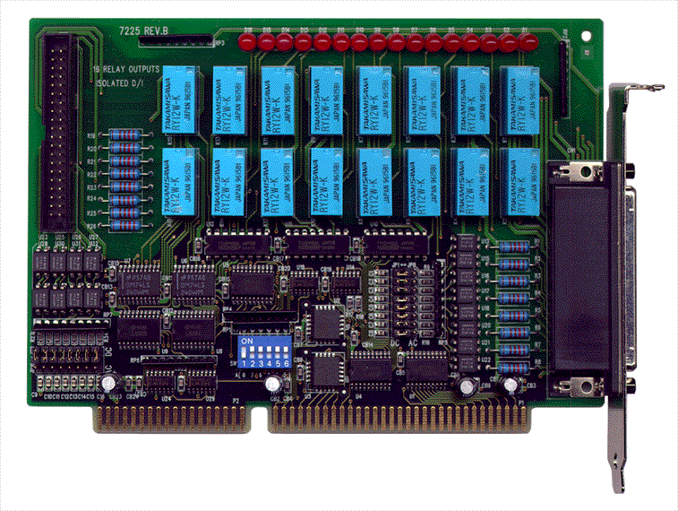
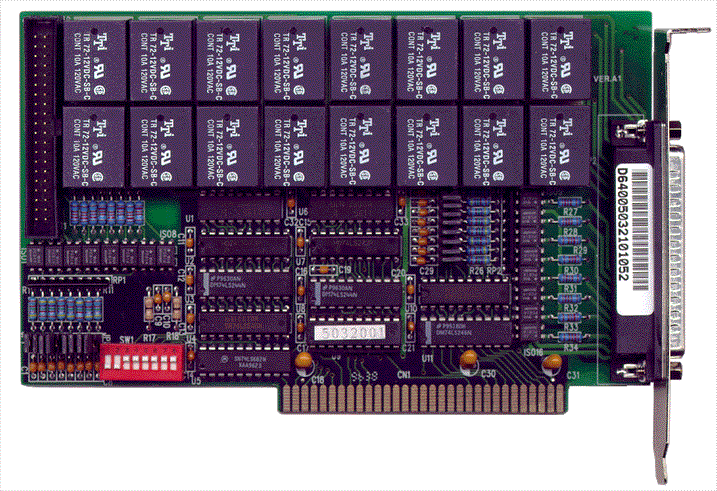
The ADLINK NuDAQ ACL‑7225 is an industrial‑grade ISA bus card designed for digital input/output control applications. It integrates 16 relay actuator outputs and 16 opto‑isolated, polarity‑free digital input channels, providing a robust interface between a PC‑based control system and external industrial devices. The card is engineered for high isolation, flexible input configuration (AC/DC), and reliable relay switching, making it suitable for automation, energy management, and laboratory control systems.
### 2. Key Features
- 16 Relay Actuator Outputs:
Each relay can control external devices such as solenoids, lamps, or contactors. Relays are a mix of Form A and Form C types for versatile switching configurations.
- 16 Opto‑Isolated Digital Inputs:
Each input channel is isolated using PC‑814 optocouplers, supporting both AC and DC signals without polarity sensitivity.
- High Isolation Voltage:
1,000 V DC isolation between channels and between channel and ground, ensuring protection against industrial noise and ground loops.
- Polarity‑Free Input Design:
Inputs accept either AC or DC signals without concern for polarity, simplifying wiring and reducing installation errors.
- Selectable Input Filtering:
Each input channel can be configured via jumper for AC‑filtered or non‑filtered operation, optimizing response time or noise immunity.
- LED Status Indicators:
Each relay output is accompanied by a red LED to visually indicate its energized (ON) or de‑energized (OFF) state.
- On‑Board Relay Drivers:
Integrated driver circuits ensure reliable relay actuation without external components.
- Standard Connectors:
Two 37‑pin D‑type female connectors provide easy access to all I/O channels. A 40‑pin header and conversion cable are included.
- ISA Bus Compatibility:
Fully compatible with IBM PC‑AT ISA bus architecture, occupying 8 consecutive I/O addresses (4 used).
- Software Support:
Compatible with DOS, Windows 95/98/NT, and LabVIEW environments through ADLINK’s ACLS‑DLL1 and ACLS‑LVIEW software libraries.
### 3. Technical Specifications
Relay Outputs
- Type: Double‑Pole‑Double‑Throw (DPDT)
- Quantity: 16 channels
- R0–R4, R8–R12: Form C (changeover)
- R5–R7, R13–R15: Form A (normally open)
- Contact Rating: 120 VAC @ 0.5 A or 24 VDC @ 1 A
- Contact Type: Bifurcated contacts for improved reliability
- Contact Resistance: ≤ 100 mΩ
- Relay Coil Voltage: +12 V DC @ 33 mA per relay
- Relay Switching Time: 5 ms typical (ON/OFF)
Isolated Digital Inputs
- Opto‑Isolator Device: PC‑814
- Channels: 16
- Input Type: AC or DC, polarity‑free
- Input Voltage Range: 5 – 24 V DC or AC (50 – 1,000 Hz)
- Input Resistance: 1.2 kΩ
- Isolation Voltage: 1,000 V channel‑to‑channel and channel‑to‑ground
- Response Time:
- 20 µs (without AC filter)
- 2.2 ms (with AC filter)
Power Requirements
- +5 V DC: 310 mA typical
- +12 V DC: 550 mA maximum (all relays energized)
Environmental Conditions
- Operating Temperature: 0 °C – 50 °C
- Storage Temperature: −20 °C – 80 °C
- Humidity: 5 – 90 % RH, non‑condensing
Physical Characteristics
- Dimensions: 177 mm (L) × 122 mm (W)
- Weight: Approx. 200 g (typical board weight)
- Connectors:
- One 37‑pin D‑type female connector (rear panel)
- One 40‑pin header (on‑board)
- Includes 40‑pin to 37‑pin converter cable
### 4. Functionality
The ACL‑7225 functions as a digital I/O interface between a host PC and external control devices. It provides:
- Relay Output Control:
Each relay channel can be individually switched ON or OFF via software commands. The relays can drive external loads such as solenoids, contactors, or indicator lamps. The relay’s LED indicator provides immediate visual feedback.
- Isolated Digital Input Monitoring:
The 16 opto‑isolated inputs detect external logic or contact closures. Isolation prevents ground loops and protects the PC from voltage transients. Each input can be configured for AC or DC operation using jumpers (JP1–JP16).
- Polarity‑Free Operation:
Inputs accept signals regardless of polarity, simplifying wiring in field installations.
- Register‑Based I/O Access:
The card uses 8 consecutive I/O addresses (4 active). Registers are mapped as follows:
- Base + 0: Relay outputs R0–R7
- Base + 1: Relay outputs R8–R15
- Base + 2: Isolated inputs DI0–DI7
- Base + 3: Isolated inputs DI8–DI15
- Software Control:
Users can control and monitor I/O channels using direct port access commands (`INP`, `OUTP`) in C, BASIC, or assembly. High‑level libraries (ACLS‑DLL1, ACLS‑LVIEW) simplify programming under Windows or LabVIEW.
Typical Applications:
- Industrial automation and process control
- Energy management systems
- Laboratory instrumentation and test automation
- Machine status monitoring and limit switch sensing
- External relay driving and signal switching
Compatibility:
- IBM PC‑AT and compatible ISA bus systems
- Supported operating systems: DOS, Windows 95/98/NT
- Software integration with LabVIEW via ACLS‑LVIEW
### 5. Components & Accessories
Included Items:
- ACL‑7225 Relay Actuator & Isolated D/I Card
- Two DB‑37 male connector assemblies
- 40‑pin to DB‑37 converter flat cable
- ADLINK software CD (includes DOS library, utilities, and documentation)
- Printed User’s Manual
Optional Accessories:
- ACLS‑DLL1 Windows DLL software package (licensed)
- ACLS‑LVIEW LabVIEW VI library
- ACL‑10437 cable assembly (for external connection)
Connectors:
- CON1: 40‑pin header (on‑board)
- CON2: 37‑pin D‑type female connector (rear panel)
- Conversion Cable: 40‑pin ribbon to 37‑pin D‑sub male
Pin Assignments:
Each connector provides access to relay contacts (NO, NC, COM) and digital input terminals (DIA, DIB). Inputs are polarity‑free; signals can be connected to either terminal without regard to polarity.
### 6. Installation & Setup
Pre‑Installation Precautions:
- Handle the card using anti‑static precautions (ESD wrist strap, grounded mat).
- Inspect for physical damage before installation.
- Do not apply power if the card appears damaged.
Installation Steps:
1. Power off the PC and remove the cover.
2. Insert the ACL‑7225 into an available ISA slot.
3. Secure the card with the mounting screw.
4. Connect external devices via the 37‑pin D‑sub connectors.
5. Configure jumpers and DIP switches as required.
6. Install the DOS or Windows software library from the ADLINK CD.
Base Address Configuration:
- The card occupies 8 consecutive I/O addresses (4 used).
- Base address range: 200h – 3FFh.
- Default base address: 300h.
- Configured via 6‑position DIP switch SW1 (A8–A3).
- Ensure no conflict with other devices.
Input Signal Type Selection:
- Jumpers JP1–JP16 configure each input channel for AC or DC operation.
- Default setting: DC input.
- AC position enables internal filtering for AC signals.
Software Installation:
- DOS library: install via `SETUP` in directory `\NuDAQISA\7225` on the ADLINK CD.
- Windows DLL (ACLS‑DLL1) and LabVIEW VI (ACLS‑LVIEW) available separately.
### 7. Performance & Capabilities
Relay Performance:
- Switching speed: 5 ms typical
- Contact life: dependent on load type and switching frequency
- Supports both low‑voltage DC and moderate AC loads
- LED indicators provide real‑time relay status feedback
Input Performance:
- Fast response (20 µs) for DC signals without filtering
- Noise‑immune operation (2.2 ms) with AC filter enabled
- Reliable isolation up to 1 kV ensures signal integrity in noisy environments
Electrical Efficiency:
- Low power consumption (≤ 0.86 W @ +5 V, ≤ 6.6 W @ +12 V with all relays ON)
- Efficient opto‑isolation minimizes current draw per channel
Limitations:
- Designed for low‑current switching (≤ 1 A @ 24 VDC or 0.5 A @ 120 VAC)
- Not intended for high‑power or high‑frequency switching applications
- Requires ISA bus slot (not compatible with PCI or PCIe systems without adapter)
### 8. Standards & Compliance
- Bus Interface: IBM PC‑AT ISA standard
- Isolation: 1,000 V DC channel‑to‑channel and channel‑to‑ground
- Operating Environment: Industrial grade, 0 °C – 50 °C
- Humidity: 5 – 90 % RH, non‑condensing
- Safety & Reliability: Designed for industrial automation environments with protection against ground loops and voltage spikes
- Software Compatibility: DOS, Windows 95/98/NT, LabVIEW
- Trademark: NuDAQ® is a registered trademark of ADLINK Technology Inc.
### 9. Additional Information
Warranty:
- Duration: 1 year from date of purchase
- Coverage: Defects in materials and workmanship
- Exclusions:
- Damage due to misuse, modification, or operation beyond specifications
- Units with removed or altered serial numbers
- Consequential damages are excluded
- Remedy: Repair or replacement at ADLINK’s discretion
- Return Policy: Product must be securely packaged and shipped prepaid with proof of purchase.
Technical Support & Service:
- ADLINK Technology Inc.
9F, No. 166, Jian Yi Road, Chungho City, Taipei 235, Taiwan, R.O.C.
Tel: +886‑2‑82265877 Fax: +886‑2‑82265717
Email: service@adlink.com.tw Web: [www.adlinktech.com](http://www.adlinktech.com)
Support Contacts:
- General Service: service@adlink.com.tw
- NuDAQ Products: nudaq@adlink.com.tw
- NuDAM Modules: nudam@adlink.com.tw
- NuIPC Systems: nuipc@adlink.com.tw
- NuPRO Boards: nupro@adlink.com.tw
- Software Support: sw@adlink.com.tw
Maintenance:
- Periodically inspect connectors and relays for contamination or oxidation.
- Ensure adequate ventilation within the PC chassis.
- Avoid exposure to excessive humidity or vibration.
- Replace relays if contact wear or failure is observed.
Software Updates:
- Updated drivers and libraries are available from ADLINK’s website.
- Users are encouraged to register their product for update notifications.
Documentation:
- User’s Guide (Rev. 3.23, June 8 2000)
- ACLS‑DLL1 Function Reference Manual
- ACLS‑LVIEW Integration Guide
### Summary
The ADLINK NuDAQ ACL‑7225 is a robust, industrial‑grade ISA digital I/O card combining 16 relay outputs and 16 opto‑isolated digital inputs in a compact 177 × 122 mm form factor. Its design emphasizes electrical isolation, flexible input configuration, and reliable relay control, making it ideal for industrial automation, laboratory instrumentation, and energy management systems. With its 1 kV isolation, selectable AC/DC input modes, and comprehensive software support, the ACL‑7225 provides a dependable interface between PC‑based control systems and external devices.
The card’s modular configuration, LED indicators, and jumper‑selectable options simplify installation and maintenance, while ADLINK’s software libraries and technical support ensure seamless integration into both legacy and modern control environments.

### 1. Product Overview
Product Name: ACL‑7225
Model: ACL‑7225 / ACL‑7225B
Series: NuDAQ® ISA Digital I/O Series
Article Number: ACL‑7225
Manufacturer: ADLINK Technology Inc.
Manufacturer Website: [www.adlinktech.com](http://www.adlinktech.com)
Form Factor: ISA Bus Expansion Card
Product Type: 16‑Channel Relay Actuator and 16‑Channel Isolated Digital Input (D/I) Card
The ADLINK NuDAQ ACL‑7225 is an industrial‑grade ISA bus card designed for digital input/output control applications. It integrates 16 relay actuator outputs and 16 opto‑isolated, polarity‑free digital input channels, providing a robust interface between a PC‑based control system and external industrial devices. The card is engineered for high isolation, flexible input configuration (AC/DC), and reliable relay switching, making it suitable for automation, energy management, and laboratory control systems.
### 2. Key Features
- 16 Relay Actuator Outputs:
Each relay can control external devices such as solenoids, lamps, or contactors. Relays are a mix of Form A and Form C types for versatile switching configurations.
- 16 Opto‑Isolated Digital Inputs:
Each input channel is isolated using PC‑814 optocouplers, supporting both AC and DC signals without polarity sensitivity.
- High Isolation Voltage:
1,000 V DC isolation between channels and between channel and ground, ensuring protection against industrial noise and ground loops.
- Polarity‑Free Input Design:
Inputs accept either AC or DC signals without concern for polarity, simplifying wiring and reducing installation errors.
- Selectable Input Filtering:
Each input channel can be configured via jumper for AC‑filtered or non‑filtered operation, optimizing response time or noise immunity.
- LED Status Indicators:
Each relay output is accompanied by a red LED to visually indicate its energized (ON) or de‑energized (OFF) state.
- On‑Board Relay Drivers:
Integrated driver circuits ensure reliable relay actuation without external components.
- Standard Connectors:
Two 37‑pin D‑type female connectors provide easy access to all I/O channels. A 40‑pin header and conversion cable are included.
- ISA Bus Compatibility:
Fully compatible with IBM PC‑AT ISA bus architecture, occupying 8 consecutive I/O addresses (4 used).
- Software Support:
Compatible with DOS, Windows 95/98/NT, and LabVIEW environments through ADLINK’s ACLS‑DLL1 and ACLS‑LVIEW software libraries.
### 3. Technical Specifications
Relay Outputs
- Type: Double‑Pole‑Double‑Throw (DPDT)
- Quantity: 16 channels
- R0–R4, R8–R12: Form C (changeover)
- R5–R7, R13–R15: Form A (normally open)
- Contact Rating: 120 VAC @ 0.5 A or 24 VDC @ 1 A
- Contact Type: Bifurcated contacts for improved reliability
- Contact Resistance: ≤ 100 mΩ
- Relay Coil Voltage: +12 V DC @ 33 mA per relay
- Relay Switching Time: 5 ms typical (ON/OFF)
Isolated Digital Inputs
- Opto‑Isolator Device: PC‑814
- Channels: 16
- Input Type: AC or DC, polarity‑free
- Input Voltage Range: 5 – 24 V DC or AC (50 – 1,000 Hz)
- Input Resistance: 1.2 kΩ
- Isolation Voltage: 1,000 V channel‑to‑channel and channel‑to‑ground
- Response Time:
- 20 µs (without AC filter)
- 2.2 ms (with AC filter)
Power Requirements
- +5 V DC: 310 mA typical
- +12 V DC: 550 mA maximum (all relays energized)
Environmental Conditions
- Operating Temperature: 0 °C – 50 °C
- Storage Temperature: −20 °C – 80 °C
- Humidity: 5 – 90 % RH, non‑condensing
Physical Characteristics
- Dimensions: 177 mm (L) × 122 mm (W)
- Weight: Approx. 200 g (typical board weight)
- Connectors:
- One 37‑pin D‑type female connector (rear panel)
- One 40‑pin header (on‑board)
- Includes 40‑pin to 37‑pin converter cable
### 4. Functionality
The ACL‑7225 functions as a digital I/O interface between a host PC and external control devices. It provides:
- Relay Output Control:
Each relay channel can be individually switched ON or OFF via software commands. The relays can drive external loads such as solenoids, contactors, or indicator lamps. The relay’s LED indicator provides immediate visual feedback.
- Isolated Digital Input Monitoring:
The 16 opto‑isolated inputs detect external logic or contact closures. Isolation prevents ground loops and protects the PC from voltage transients. Each input can be configured for AC or DC operation using jumpers (JP1–JP16).
- Polarity‑Free Operation:
Inputs accept signals regardless of polarity, simplifying wiring in field installations.
- Register‑Based I/O Access:
The card uses 8 consecutive I/O addresses (4 active). Registers are mapped as follows:
- Base + 0: Relay outputs R0–R7
- Base + 1: Relay outputs R8–R15
- Base + 2: Isolated inputs DI0–DI7
- Base + 3: Isolated inputs DI8–DI15
- Software Control:
Users can control and monitor I/O channels using direct port access commands (`INP`, `OUTP`) in C, BASIC, or assembly. High‑level libraries (ACLS‑DLL1, ACLS‑LVIEW) simplify programming under Windows or LabVIEW.
Typical Applications:
- Industrial automation and process control
- Energy management systems
- Laboratory instrumentation and test automation
- Machine status monitoring and limit switch sensing
- External relay driving and signal switching
Compatibility:
- IBM PC‑AT and compatible ISA bus systems
- Supported operating systems: DOS, Windows 95/98/NT
- Software integration with LabVIEW via ACLS‑LVIEW
### 5. Components & Accessories
Included Items:
- ACL‑7225 Relay Actuator & Isolated D/I Card
- Two DB‑37 male connector assemblies
- 40‑pin to DB‑37 converter flat cable
- ADLINK software CD (includes DOS library, utilities, and documentation)
- Printed User’s Manual
Optional Accessories:
- ACLS‑DLL1 Windows DLL software package (licensed)
- ACLS‑LVIEW LabVIEW VI library
- ACL‑10437 cable assembly (for external connection)
Connectors:
- CON1: 40‑pin header (on‑board)
- CON2: 37‑pin D‑type female connector (rear panel)
- Conversion Cable: 40‑pin ribbon to 37‑pin D‑sub male
Pin Assignments:
Each connector provides access to relay contacts (NO, NC, COM) and digital input terminals (DIA, DIB). Inputs are polarity‑free; signals can be connected to either terminal without regard to polarity.
### 6. Installation & Setup
Pre‑Installation Precautions:
- Handle the card using anti‑static precautions (ESD wrist strap, grounded mat).
- Inspect for physical damage before installation.
- Do not apply power if the card appears damaged.
Installation Steps:
1. Power off the PC and remove the cover.
2. Insert the ACL‑7225 into an available ISA slot.
3. Secure the card with the mounting screw.
4. Connect external devices via the 37‑pin D‑sub connectors.
5. Configure jumpers and DIP switches as required.
6. Install the DOS or Windows software library from the ADLINK CD.
Base Address Configuration:
- The card occupies 8 consecutive I/O addresses (4 used).
- Base address range: 200h – 3FFh.
- Default base address: 300h.
- Configured via 6‑position DIP switch SW1 (A8–A3).
- Ensure no conflict with other devices.
Input Signal Type Selection:
- Jumpers JP1–JP16 configure each input channel for AC or DC operation.
- Default setting: DC input.
- AC position enables internal filtering for AC signals.
Software Installation:
- DOS library: install via `SETUP` in directory `\NuDAQISA\7225` on the ADLINK CD.
- Windows DLL (ACLS‑DLL1) and LabVIEW VI (ACLS‑LVIEW) available separately.
### 7. Performance & Capabilities
Relay Performance:
- Switching speed: 5 ms typical
- Contact life: dependent on load type and switching frequency
- Supports both low‑voltage DC and moderate AC loads
- LED indicators provide real‑time relay status feedback
Input Performance:
- Fast response (20 µs) for DC signals without filtering
- Noise‑immune operation (2.2 ms) with AC filter enabled
- Reliable isolation up to 1 kV ensures signal integrity in noisy environments
Electrical Efficiency:
- Low power consumption (≤ 0.86 W @ +5 V, ≤ 6.6 W @ +12 V with all relays ON)
- Efficient opto‑isolation minimizes current draw per channel
Limitations:
- Designed for low‑current switching (≤ 1 A @ 24 VDC or 0.5 A @ 120 VAC)
- Not intended for high‑power or high‑frequency switching applications
- Requires ISA bus slot (not compatible with PCI or PCIe systems without adapter)
### 8. Standards & Compliance
- Bus Interface: IBM PC‑AT ISA standard
- Isolation: 1,000 V DC channel‑to‑channel and channel‑to‑ground
- Operating Environment: Industrial grade, 0 °C – 50 °C
- Humidity: 5 – 90 % RH, non‑condensing
- Safety & Reliability: Designed for industrial automation environments with protection against ground loops and voltage spikes
- Software Compatibility: DOS, Windows 95/98/NT, LabVIEW
- Trademark: NuDAQ® is a registered trademark of ADLINK Technology Inc.
### 9. Additional Information
Warranty:
- Duration: 1 year from date of purchase
- Coverage: Defects in materials and workmanship
- Exclusions:
- Damage due to misuse, modification, or operation beyond specifications
- Units with removed or altered serial numbers
- Consequential damages are excluded
- Remedy: Repair or replacement at ADLINK’s discretion
- Return Policy: Product must be securely packaged and shipped prepaid with proof of purchase.
Technical Support & Service:
- ADLINK Technology Inc.
9F, No. 166, Jian Yi Road, Chungho City, Taipei 235, Taiwan, R.O.C.
Tel: +886‑2‑82265877 Fax: +886‑2‑82265717
Email: service@adlink.com.tw Web: [www.adlinktech.com](http://www.adlinktech.com)
Support Contacts:
- General Service: service@adlink.com.tw
- NuDAQ Products: nudaq@adlink.com.tw
- NuDAM Modules: nudam@adlink.com.tw
- NuIPC Systems: nuipc@adlink.com.tw
- NuPRO Boards: nupro@adlink.com.tw
- Software Support: sw@adlink.com.tw
Maintenance:
- Periodically inspect connectors and relays for contamination or oxidation.
- Ensure adequate ventilation within the PC chassis.
- Avoid exposure to excessive humidity or vibration.
- Replace relays if contact wear or failure is observed.
Software Updates:
- Updated drivers and libraries are available from ADLINK’s website.
- Users are encouraged to register their product for update notifications.
Documentation:
- User’s Guide (Rev. 3.23, June 8 2000)
- ACLS‑DLL1 Function Reference Manual
- ACLS‑LVIEW Integration Guide
### Summary
The ADLINK NuDAQ ACL‑7225 is a robust, industrial‑grade ISA digital I/O card combining 16 relay outputs and 16 opto‑isolated digital inputs in a compact 177 × 122 mm form factor. Its design emphasizes electrical isolation, flexible input configuration, and reliable relay control, making it ideal for industrial automation, laboratory instrumentation, and energy management systems. With its 1 kV isolation, selectable AC/DC input modes, and comprehensive software support, the ACL‑7225 provides a dependable interface between PC‑based control systems and external devices.
The card’s modular configuration, LED indicators, and jumper‑selectable options simplify installation and maintenance, while ADLINK’s software libraries and technical support ensure seamless integration into both legacy and modern control environments.

-
Digital_IO_Selection_Guide_20151230.pdf
PDF Catalog
-
A7225 Manual.PDF
Manual
- ACL-10437 - 40 pin to DB37 m slot adapter
- DIN-37D-01 - 37pin D-type panel DIN rail w/o cable