LOOKING FOR THE RIGHT
INDUSTRIAL SOLUTION?
Discover embedded, communication and automation solutions tailored to your application.
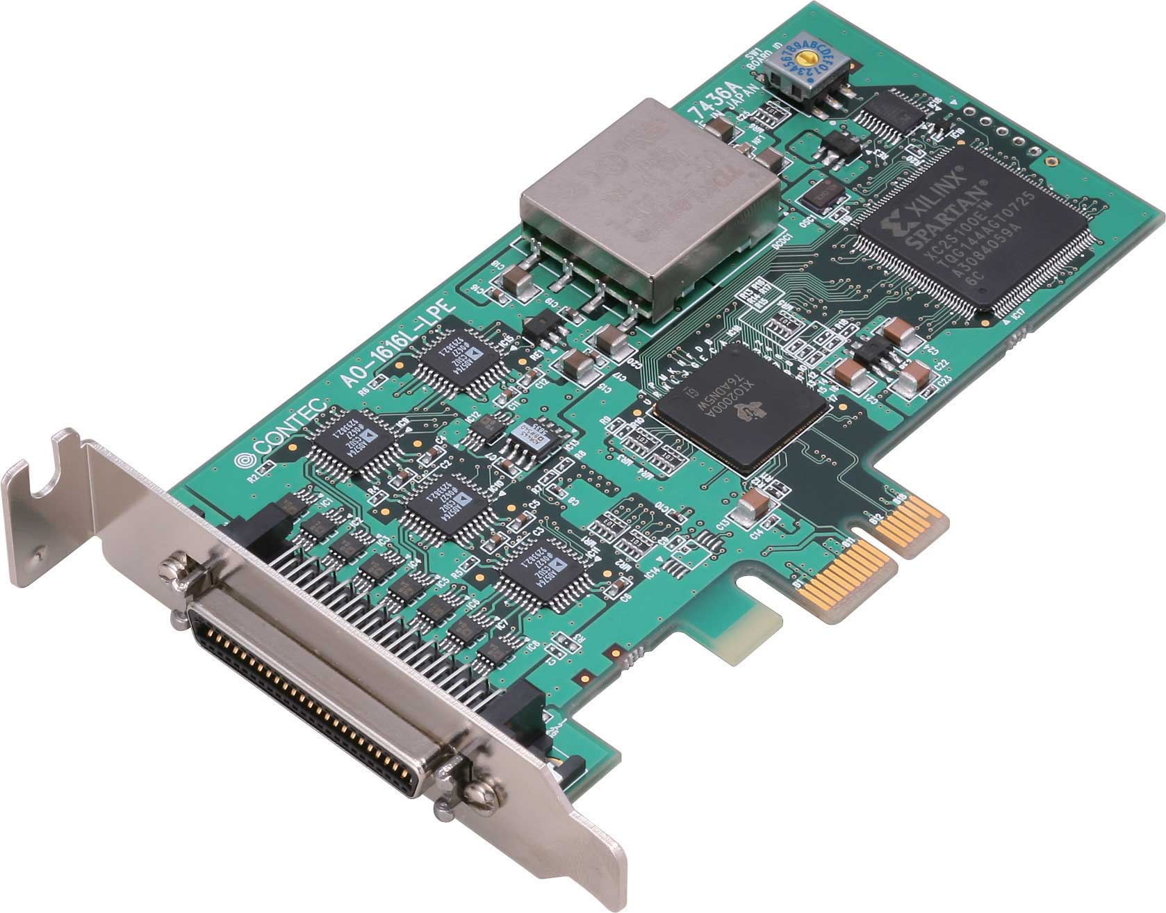
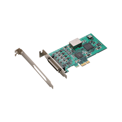
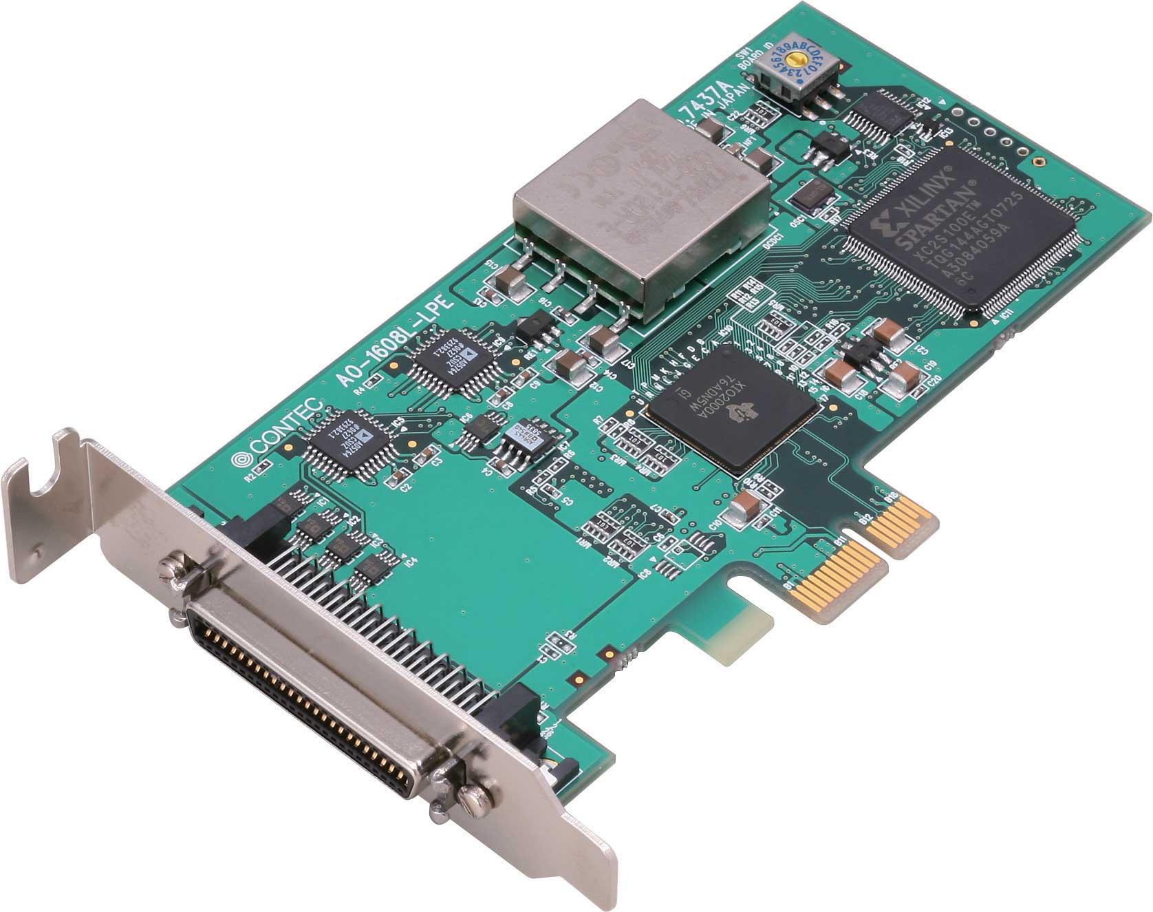
AO-1616L-LPE
PCIe Low Profile DA 100kS/s 16 Bit 16 CH + 4*DI + 4*DO + Cou
830,00 EUR
including VAT 987.70 EUR
- High‑precision 16‑bit Analog Output: Sixteen independent unisolated channels with bipolar ±10 V range and ≤ 1 Ω output impedance provide fine‑resolution voltage generation for control and simulation tasks.
- High Speed Conversion: 10 µs conversion time per channel (100 kS/s aggregate rate) enables smooth waveform generation and dynamic signal output.
- Integrated Digital I/O: Four LVTTL‑level inputs and four LVTTL‑level outputs (positive logic) allow synchronous digital control and status monitoring.
- 32‑bit Counter/Timer: One LVTTL‑level up‑count channel with gate and up inputs and a count‑match pulse output supports event counting up to 10 MHz.
- Flexible Trigger and Clock Control: Sampling start/stop can be initiated by software commands or external LVTTL triggers; sampling clock can be internal or external with edge selection (rising/falling).
- 1 k‑word On‑board Buffer: Configurable as FIFO or RING memory for continuous or cyclic output independent of host CPU load.
- Digital Filter on External Signals: 1 µs software‑selectable filter suppresses chattering and false trigger detection on external and digital inputs.
- Safe Power‑on Design: All analog outputs are forced to 0 V at power‑up to protect connected equipment from transients.
- Software Calibration: Full software‑based gain/offset adjustment with storage of user calibration data in non‑volatile memory.
- Driver and Library Support: Bundled Windows and Linux drivers (API‑PAC W32/LNX) with sample programs; MATLAB ML‑DAQ and LabVIEW VI‑DAQ libraries available free from CONTEC.
- Compatibility: Connector and function compatible with legacy PCI board DA16‑16(LPCI)L for easy system migration.
- Dual Bracket Support: Supplied with both low‑profile and standard PCI brackets for installation flexibility.
- Regulatory Compliance: RoHS and VCCI certified.
- High Speed Conversion: 10 µs conversion time per channel (100 kS/s aggregate rate) enables smooth waveform generation and dynamic signal output.
- Integrated Digital I/O: Four LVTTL‑level inputs and four LVTTL‑level outputs (positive logic) allow synchronous digital control and status monitoring.
- 32‑bit Counter/Timer: One LVTTL‑level up‑count channel with gate and up inputs and a count‑match pulse output supports event counting up to 10 MHz.
- Flexible Trigger and Clock Control: Sampling start/stop can be initiated by software commands or external LVTTL triggers; sampling clock can be internal or external with edge selection (rising/falling).
- 1 k‑word On‑board Buffer: Configurable as FIFO or RING memory for continuous or cyclic output independent of host CPU load.
- Digital Filter on External Signals: 1 µs software‑selectable filter suppresses chattering and false trigger detection on external and digital inputs.
- Safe Power‑on Design: All analog outputs are forced to 0 V at power‑up to protect connected equipment from transients.
- Software Calibration: Full software‑based gain/offset adjustment with storage of user calibration data in non‑volatile memory.
- Driver and Library Support: Bundled Windows and Linux drivers (API‑PAC W32/LNX) with sample programs; MATLAB ML‑DAQ and LabVIEW VI‑DAQ libraries available free from CONTEC.
- Compatibility: Connector and function compatible with legacy PCI board DA16‑16(LPCI)L for easy system migration.
- Dual Bracket Support: Supplied with both low‑profile and standard PCI brackets for installation flexibility.
- Regulatory Compliance: RoHS and VCCI certified.
Comprehensive Product Summary – AO‑1616L‑LPE PCI Express Low‑Profile Analog Output Board
*(Approx. 12 000 characters / ~3000 tokens)*
### 1. Product Overview
Product Name: AO‑1616L‑LPE
Article Number: AO‑1616L‑LPE
Series: PCI Express Low‑Profile Analog Output Boards
Manufacturer: CONTEC CO., LTD., Osaka Japan
Version: Ver. 1.03
The AO‑1616L‑LPE is a low‑profile PCI Express bus‑compliant multifunction data‑acquisition and signal‑generation board providing high‑precision analog output capabilities for PC‑based measurement and control systems. It offers 16 independent 16‑bit analog output channels with a maximum conversion rate of 100 kS/s (10 µs per channel), supplemented by four digital inputs, four digital outputs, and a 32‑bit counter input/output channel. The board is designed for industrial and laboratory applications requiring precise voltage generation, waveform output, and synchronized digital control within a compact PCIe form factor compatible with both low‑profile and standard slots.
### 2. Key Features
- High‑precision 16‑bit Analog Output: Sixteen independent unisolated channels with bipolar ±10 V range and ≤ 1 Ω output impedance provide fine‑resolution voltage generation for control and simulation tasks.
- High Speed Conversion: 10 µs conversion time per channel (100 kS/s aggregate rate) enables smooth waveform generation and dynamic signal output.
- Integrated Digital I/O: Four LVTTL‑level inputs and four LVTTL‑level outputs (positive logic) allow synchronous digital control and status monitoring.
- 32‑bit Counter/Timer: One LVTTL‑level up‑count channel with gate and up inputs and a count‑match pulse output supports event counting up to 10 MHz.
- Flexible Trigger and Clock Control: Sampling start/stop can be initiated by software commands or external LVTTL triggers; sampling clock can be internal or external with edge selection (rising/falling).
- 1 k‑word On‑board Buffer: Configurable as FIFO or RING memory for continuous or cyclic output independent of host CPU load.
- Digital Filter on External Signals: 1 µs software‑selectable filter suppresses chattering and false trigger detection on external and digital inputs.
- Safe Power‑on Design: All analog outputs are forced to 0 V at power‑up to protect connected equipment from transients.
- Software Calibration: Full software‑based gain/offset adjustment with storage of user calibration data in non‑volatile memory.
- Driver and Library Support: Bundled Windows and Linux drivers (API‑PAC W32/LNX) with sample programs; MATLAB ML‑DAQ and LabVIEW VI‑DAQ libraries available free from CONTEC.
- Compatibility: Connector and function compatible with legacy PCI board DA16‑16(LPCI)L for easy system migration.
- Dual Bracket Support: Supplied with both low‑profile and standard PCI brackets for installation flexibility.
- Regulatory Compliance: RoHS and VCCI certified.
### 3. Technical Specifications
| Parameter | Specification |
|:--|:--|
| Analog Output | Unisolated 16 channels |
| Output Range | Bipolar ±10 V |
| Resolution | 16 bits (1 LSB ≈ 0.305 mV at ±10 V) |
| Output Impedance | ≤ 1 Ω |
| Max Output Current | ±3 mA per channel |
| Non‑linearity Error | ±5 LSB (≈ 0.1 % FS at 0–50 °C) |
| Conversion Speed | 10 µs per channel (100 kS/s) |
| Buffer Memory | 1 k word (FIFO or RING) |
| Start Trigger | Software or external LVTTL (rising/falling edge selectable) |
| Stop Trigger | Sampling count, external trigger, or software |
| External Clock | LVTTL level (rising/falling edge selectable) |
| Digital Filter | 1 µs software‑selectable |
| Digital I/O | 4 inputs + 4 outputs, LVTTL positive logic |
| Input Type | Unisolated LVTTL (High ≥ 2.0 V, Low ≤ 0.8 V typ.) |
| Output Drive | Sink/source 8 mA typ. |
| Counter | 1 channel, 32‑bit up counter |
| Max Count | 0xFFFFFFFF (4 294 967 295) |
| External Inputs | Gate (High enable) and Up (rising edge) LVTTL |
| External Output | Count‑match pulse LVTTL positive logic |
| Response Frequency | 10 MHz max |
| Common Section | |
| Bus Interface | PCI Express Base Spec Rev 1.0a x1 lane |
| I/O Address Space | 64 ports |
| Interrupt Level | INTA (shared for errors and events) |
| Connector | 50‑pin mini‑ribbon 3M 10250‑52A2JL |
| Power Consumption | 3.3 V DC 310 mA max; 12 V DC 410 mA max |
| Operating Temperature | 0 – 50 °C |
| Operating Humidity | 10 – 90 % RH (non‑condensing) |
| Dimensions | 121.69 (L) × 67.90 (H) mm |
| Weight | Approx. 70 g |
| Certifications | RoHS, VCCI Class A |
### 4. Functionality and Applications
Operating Principle:
The AO‑1616L‑LPE converts digital data from the host PC into analog voltages through 16‑bit DACs. Each channel can output a programmable voltage within ±10 V range. Sampling is timed by an internal clock or an external LVTTL clock input. Start and stop events are controlled via software commands or external triggers. The on‑board buffer permits continuous or cyclic output without CPU intervention.
Use Cases:
- Waveform generation for device testing and simulation.
- Control of actuators, power supplies, and analog drives in automation systems.
- Signal output for hardware‑in‑the‑loop (HIL) and real‑time model testing.
- Analog stimulus for data acquisition and measurement equipment.
- General‑purpose laboratory signal generation and process control.
Compatibility:
Fully supported under Windows and Linux via API‑PAC drivers; integrates with MATLAB Data Acquisition Toolbox and NI LabVIEW through ML‑DAQ and VI‑DAQ libraries. Connector and pinout are identical to the legacy PCI DA16‑16(LPCI)L board, allowing drop‑in replacement in existing systems.
### 5. Components and Accessories
Included Items:
- AO‑1616L‑LPE board × 1
- Low‑profile bracket (pre‑installed) and standard bracket × 1
- Driver and utility disk (API‑PAC W32) × 1
- First Step Guide and User’s Guide × 1
- Warranty certificate × 1
- Serial number label × 1
Optional Cables:
- PCB50PS‑0.5P (0.5 m) – Shielded 50‑pin mini‑ribbon both ends
- PCB50PS‑1.5P (1.5 m) – Shielded 50‑pin mini‑ribbon both ends
- PCA50PS‑0.5P (0.5 m) – Shielded 50‑pin one end open for custom wiring
- PCA50PS‑1.5P (1.5 m) – Shielded 50‑pin one end open
Optional Terminal Unit:
- EPD‑50A (M3 × 50 P screw terminal, spring‑up type) – requires PCB50PS cable.
Connector Type: 3M 10250‑52A2JL (compatible with 3M 10150‑6000EL).
### 6. Installation and Setup
Hardware Preparation:
1. Power off the PC and remove the cover.
2. Select appropriate bracket (low‑profile or standard) and mount the board in a PCI Express x1 slot.
3. Secure with screw and reassemble the chassis.
4. Connect external devices via CN1 50‑pin connector using shielded cables.
Board ID Setting: Rotary switch SW1 (0–Fh) assigns unique ID when multiple boards are installed.
Software Installation:
- Install API‑PAC(W32) driver before hardware insertion on Windows.
- For Linux, compile and install API‑AIO(LNX) module from provided source (tar package caioXXX.tgz).
- After installation, use Device Manager to verify recognition and assign device name.
Diagnostic Program: Included utility verifies analog output, digital I/O, and counter functions and generates a diagnostic report listing device settings and status.
Connection Guidelines:
- Separate analog ground (AGND) and digital ground (DGND) to minimize noise.
- Do not short outputs to ground or other outputs.
- Use shielded cables for long runs or noisy environments.
- All outputs reset to 0 V at power‑on.
### 7. Performance and Capabilities
Analog Output Operation:
- Supports continuous (FIFO) or cyclic (RING) buffer modes. FIFO enables streaming waveforms with real‑time data updates; RING mode repeats a stored pattern for periodic signals.
- Sampling frequency determined by internal clock or external LVTTL clock input.
- Start/stop trigger sources selectable (software command or external edge).
- Event notifications include conversion start, repeat end, operation end, sample count complete, and error events (sampling clock or conversion error).
Counter Function:
- Up‑count mode with compare match and auto‑reload capability.
- Digital filter (1 µs) prevents false counts from noise.
- Events generated on compare match, overrun, and operation error.
- Count value readable in real time; reset via software command.
Digital I/O:
- Bit‑ or byte‑level read/write operations.
- Input filter (1 µs) selectable to suppress chatter.
- Outputs can drive LEDs or logic inputs (up to 8 mA).
Timing Characteristics:
- External sampling clock delay tDEC = 100 ns.
- Settling time tWS = 10 µs.
- Trigger setup/hold times tSRS/tHRS = 100 ns (typ.).
- Counter input setup/hold tSRC/tHRC = 100 ns; output pulse width tPSC = 1 µs.
Limitations:
- Unisolated outputs require common ground reference with target device.
- Maximum output current ±3 mA; not intended for direct load driving.
- Operating temperature limited to 0–50 °C; avoid condensation and corrosive environments.
### 8. Standards and Compliance
- Bus Standard: PCI Express Base Specification Rev 1.0a (x1 lane).
- Electrical Levels: LVTTL logic for all digital I/O and control signals.
- Environmental: RoHS Directive compliant (lead‑free).
- EMC: VCCI Class A compliance for industrial environments.
- Safety: Designed for 0 V output at power‑on to prevent equipment damage.
- Compatibility: Connector and function equivalent to DA16‑16(LPCI)L (PCI) board for system migration.
### 9. Additional Information
Calibration and Maintenance:
Factory‑calibrated prior to shipment; user can re‑calibrate via software utility using a 5‑digit precision digital multimeter. Calibration data can be restored to factory defaults if required. No periodic mechanical maintenance is necessary other than keeping connectors clean and free of dust.
Software Support:
- Windows: API‑AIO(WDM) driver library (DLL interface) with sample programs for Visual C++ and Visual Basic.
- Linux: API‑AIO(LNX) shared library and kernel module with gcc samples.
- MATLAB: ML‑DAQ library integrated with Data Acquisition Toolbox.
- LabVIEW: VI‑DAQ library with function blocks matching NI DAQ VIs.
- Diagnostic and execution‑speed measurement utilities included.
Warranty and Service:
Limited three‑year warranty against defects in materials and workmanship (excluding normal wear and mechanical damage). Service requires Return Merchandise Authorization (RMA) and proof of purchase. Repairs due to misuse or modification are excluded.
Environmental and Handling Precautions:
Operate in 0–50 °C, 10–90 % RH (non‑condensing). Avoid exposure to flammable or corrosive gases. Ensure adequate PC power supply capacity. Do not insert or remove the board while power is on. Clean edge connectors with industrial alcohol if touched.
Storage and Disposal:
Store in original antistatic packaging away from moisture and magnetic fields. Dispose according to local electronic waste regulations.
Customer Support:
Up‑to‑date drivers, manuals, and sample code available at [https://www.contec.com](https://www.contec.com). Technical inquiries and RMA requests handled through authorized CONTEC offices or distributors.
### Summary
The CONTEC AO‑1616L‑LPE is a compact, high‑accuracy 16‑channel analog output solution for PCI Express systems, combining 16‑bit resolution, 100 kS/s throughput, and integrated digital I/O and counter functions in a low‑profile form factor. Its software ecosystem (API‑PAC, ML‑DAQ, VI‑DAQ) and compatibility with both Windows and Linux make it ideal for scientific instrumentation, industrial automation, and test applications requiring precise voltage generation and synchronized digital control. With software‑based calibration, robust triggering options, and compliance to RoHS and VCCI standards, the AO‑1616L‑LPE delivers a reliable and flexible platform for modern data‑acquisition and signal‑output systems.
*(Approx. 12 000 characters / ~3000 tokens)*
### 1. Product Overview
Product Name: AO‑1616L‑LPE
Article Number: AO‑1616L‑LPE
Series: PCI Express Low‑Profile Analog Output Boards
Manufacturer: CONTEC CO., LTD., Osaka Japan
Version: Ver. 1.03
The AO‑1616L‑LPE is a low‑profile PCI Express bus‑compliant multifunction data‑acquisition and signal‑generation board providing high‑precision analog output capabilities for PC‑based measurement and control systems. It offers 16 independent 16‑bit analog output channels with a maximum conversion rate of 100 kS/s (10 µs per channel), supplemented by four digital inputs, four digital outputs, and a 32‑bit counter input/output channel. The board is designed for industrial and laboratory applications requiring precise voltage generation, waveform output, and synchronized digital control within a compact PCIe form factor compatible with both low‑profile and standard slots.
### 2. Key Features
- High‑precision 16‑bit Analog Output: Sixteen independent unisolated channels with bipolar ±10 V range and ≤ 1 Ω output impedance provide fine‑resolution voltage generation for control and simulation tasks.
- High Speed Conversion: 10 µs conversion time per channel (100 kS/s aggregate rate) enables smooth waveform generation and dynamic signal output.
- Integrated Digital I/O: Four LVTTL‑level inputs and four LVTTL‑level outputs (positive logic) allow synchronous digital control and status monitoring.
- 32‑bit Counter/Timer: One LVTTL‑level up‑count channel with gate and up inputs and a count‑match pulse output supports event counting up to 10 MHz.
- Flexible Trigger and Clock Control: Sampling start/stop can be initiated by software commands or external LVTTL triggers; sampling clock can be internal or external with edge selection (rising/falling).
- 1 k‑word On‑board Buffer: Configurable as FIFO or RING memory for continuous or cyclic output independent of host CPU load.
- Digital Filter on External Signals: 1 µs software‑selectable filter suppresses chattering and false trigger detection on external and digital inputs.
- Safe Power‑on Design: All analog outputs are forced to 0 V at power‑up to protect connected equipment from transients.
- Software Calibration: Full software‑based gain/offset adjustment with storage of user calibration data in non‑volatile memory.
- Driver and Library Support: Bundled Windows and Linux drivers (API‑PAC W32/LNX) with sample programs; MATLAB ML‑DAQ and LabVIEW VI‑DAQ libraries available free from CONTEC.
- Compatibility: Connector and function compatible with legacy PCI board DA16‑16(LPCI)L for easy system migration.
- Dual Bracket Support: Supplied with both low‑profile and standard PCI brackets for installation flexibility.
- Regulatory Compliance: RoHS and VCCI certified.
### 3. Technical Specifications
| Parameter | Specification |
|:--|:--|
| Analog Output | Unisolated 16 channels |
| Output Range | Bipolar ±10 V |
| Resolution | 16 bits (1 LSB ≈ 0.305 mV at ±10 V) |
| Output Impedance | ≤ 1 Ω |
| Max Output Current | ±3 mA per channel |
| Non‑linearity Error | ±5 LSB (≈ 0.1 % FS at 0–50 °C) |
| Conversion Speed | 10 µs per channel (100 kS/s) |
| Buffer Memory | 1 k word (FIFO or RING) |
| Start Trigger | Software or external LVTTL (rising/falling edge selectable) |
| Stop Trigger | Sampling count, external trigger, or software |
| External Clock | LVTTL level (rising/falling edge selectable) |
| Digital Filter | 1 µs software‑selectable |
| Digital I/O | 4 inputs + 4 outputs, LVTTL positive logic |
| Input Type | Unisolated LVTTL (High ≥ 2.0 V, Low ≤ 0.8 V typ.) |
| Output Drive | Sink/source 8 mA typ. |
| Counter | 1 channel, 32‑bit up counter |
| Max Count | 0xFFFFFFFF (4 294 967 295) |
| External Inputs | Gate (High enable) and Up (rising edge) LVTTL |
| External Output | Count‑match pulse LVTTL positive logic |
| Response Frequency | 10 MHz max |
| Common Section | |
| Bus Interface | PCI Express Base Spec Rev 1.0a x1 lane |
| I/O Address Space | 64 ports |
| Interrupt Level | INTA (shared for errors and events) |
| Connector | 50‑pin mini‑ribbon 3M 10250‑52A2JL |
| Power Consumption | 3.3 V DC 310 mA max; 12 V DC 410 mA max |
| Operating Temperature | 0 – 50 °C |
| Operating Humidity | 10 – 90 % RH (non‑condensing) |
| Dimensions | 121.69 (L) × 67.90 (H) mm |
| Weight | Approx. 70 g |
| Certifications | RoHS, VCCI Class A |
### 4. Functionality and Applications
Operating Principle:
The AO‑1616L‑LPE converts digital data from the host PC into analog voltages through 16‑bit DACs. Each channel can output a programmable voltage within ±10 V range. Sampling is timed by an internal clock or an external LVTTL clock input. Start and stop events are controlled via software commands or external triggers. The on‑board buffer permits continuous or cyclic output without CPU intervention.
Use Cases:
- Waveform generation for device testing and simulation.
- Control of actuators, power supplies, and analog drives in automation systems.
- Signal output for hardware‑in‑the‑loop (HIL) and real‑time model testing.
- Analog stimulus for data acquisition and measurement equipment.
- General‑purpose laboratory signal generation and process control.
Compatibility:
Fully supported under Windows and Linux via API‑PAC drivers; integrates with MATLAB Data Acquisition Toolbox and NI LabVIEW through ML‑DAQ and VI‑DAQ libraries. Connector and pinout are identical to the legacy PCI DA16‑16(LPCI)L board, allowing drop‑in replacement in existing systems.
### 5. Components and Accessories
Included Items:
- AO‑1616L‑LPE board × 1
- Low‑profile bracket (pre‑installed) and standard bracket × 1
- Driver and utility disk (API‑PAC W32) × 1
- First Step Guide and User’s Guide × 1
- Warranty certificate × 1
- Serial number label × 1
Optional Cables:
- PCB50PS‑0.5P (0.5 m) – Shielded 50‑pin mini‑ribbon both ends
- PCB50PS‑1.5P (1.5 m) – Shielded 50‑pin mini‑ribbon both ends
- PCA50PS‑0.5P (0.5 m) – Shielded 50‑pin one end open for custom wiring
- PCA50PS‑1.5P (1.5 m) – Shielded 50‑pin one end open
Optional Terminal Unit:
- EPD‑50A (M3 × 50 P screw terminal, spring‑up type) – requires PCB50PS cable.
Connector Type: 3M 10250‑52A2JL (compatible with 3M 10150‑6000EL).
### 6. Installation and Setup
Hardware Preparation:
1. Power off the PC and remove the cover.
2. Select appropriate bracket (low‑profile or standard) and mount the board in a PCI Express x1 slot.
3. Secure with screw and reassemble the chassis.
4. Connect external devices via CN1 50‑pin connector using shielded cables.
Board ID Setting: Rotary switch SW1 (0–Fh) assigns unique ID when multiple boards are installed.
Software Installation:
- Install API‑PAC(W32) driver before hardware insertion on Windows.
- For Linux, compile and install API‑AIO(LNX) module from provided source (tar package caioXXX.tgz).
- After installation, use Device Manager to verify recognition and assign device name.
Diagnostic Program: Included utility verifies analog output, digital I/O, and counter functions and generates a diagnostic report listing device settings and status.
Connection Guidelines:
- Separate analog ground (AGND) and digital ground (DGND) to minimize noise.
- Do not short outputs to ground or other outputs.
- Use shielded cables for long runs or noisy environments.
- All outputs reset to 0 V at power‑on.
### 7. Performance and Capabilities
Analog Output Operation:
- Supports continuous (FIFO) or cyclic (RING) buffer modes. FIFO enables streaming waveforms with real‑time data updates; RING mode repeats a stored pattern for periodic signals.
- Sampling frequency determined by internal clock or external LVTTL clock input.
- Start/stop trigger sources selectable (software command or external edge).
- Event notifications include conversion start, repeat end, operation end, sample count complete, and error events (sampling clock or conversion error).
Counter Function:
- Up‑count mode with compare match and auto‑reload capability.
- Digital filter (1 µs) prevents false counts from noise.
- Events generated on compare match, overrun, and operation error.
- Count value readable in real time; reset via software command.
Digital I/O:
- Bit‑ or byte‑level read/write operations.
- Input filter (1 µs) selectable to suppress chatter.
- Outputs can drive LEDs or logic inputs (up to 8 mA).
Timing Characteristics:
- External sampling clock delay tDEC = 100 ns.
- Settling time tWS = 10 µs.
- Trigger setup/hold times tSRS/tHRS = 100 ns (typ.).
- Counter input setup/hold tSRC/tHRC = 100 ns; output pulse width tPSC = 1 µs.
Limitations:
- Unisolated outputs require common ground reference with target device.
- Maximum output current ±3 mA; not intended for direct load driving.
- Operating temperature limited to 0–50 °C; avoid condensation and corrosive environments.
### 8. Standards and Compliance
- Bus Standard: PCI Express Base Specification Rev 1.0a (x1 lane).
- Electrical Levels: LVTTL logic for all digital I/O and control signals.
- Environmental: RoHS Directive compliant (lead‑free).
- EMC: VCCI Class A compliance for industrial environments.
- Safety: Designed for 0 V output at power‑on to prevent equipment damage.
- Compatibility: Connector and function equivalent to DA16‑16(LPCI)L (PCI) board for system migration.
### 9. Additional Information
Calibration and Maintenance:
Factory‑calibrated prior to shipment; user can re‑calibrate via software utility using a 5‑digit precision digital multimeter. Calibration data can be restored to factory defaults if required. No periodic mechanical maintenance is necessary other than keeping connectors clean and free of dust.
Software Support:
- Windows: API‑AIO(WDM) driver library (DLL interface) with sample programs for Visual C++ and Visual Basic.
- Linux: API‑AIO(LNX) shared library and kernel module with gcc samples.
- MATLAB: ML‑DAQ library integrated with Data Acquisition Toolbox.
- LabVIEW: VI‑DAQ library with function blocks matching NI DAQ VIs.
- Diagnostic and execution‑speed measurement utilities included.
Warranty and Service:
Limited three‑year warranty against defects in materials and workmanship (excluding normal wear and mechanical damage). Service requires Return Merchandise Authorization (RMA) and proof of purchase. Repairs due to misuse or modification are excluded.
Environmental and Handling Precautions:
Operate in 0–50 °C, 10–90 % RH (non‑condensing). Avoid exposure to flammable or corrosive gases. Ensure adequate PC power supply capacity. Do not insert or remove the board while power is on. Clean edge connectors with industrial alcohol if touched.
Storage and Disposal:
Store in original antistatic packaging away from moisture and magnetic fields. Dispose according to local electronic waste regulations.
Customer Support:
Up‑to‑date drivers, manuals, and sample code available at [https://www.contec.com](https://www.contec.com). Technical inquiries and RMA requests handled through authorized CONTEC offices or distributors.
### Summary
The CONTEC AO‑1616L‑LPE is a compact, high‑accuracy 16‑channel analog output solution for PCI Express systems, combining 16‑bit resolution, 100 kS/s throughput, and integrated digital I/O and counter functions in a low‑profile form factor. Its software ecosystem (API‑PAC, ML‑DAQ, VI‑DAQ) and compatibility with both Windows and Linux make it ideal for scientific instrumentation, industrial automation, and test applications requiring precise voltage generation and synchronized digital control. With software‑based calibration, robust triggering options, and compliance to RoHS and VCCI standards, the AO‑1616L‑LPE delivers a reliable and flexible platform for modern data‑acquisition and signal‑output systems.
-
 ds_ao1616llpe_en.pdf
PDF Catalog
ds_ao1616llpe_en.pdf
PDF Catalog

No accessories available.