DIN-37D-01
LOOKING FOR THE RIGHT
INDUSTRIAL SOLUTION?
Discover embedded, communication and automation solutions tailored to your application.
- High‑Resolution Analog Output:
16‑bit D/A resolution with guaranteed 15‑bit monotonicity for precise voltage generation.
- Multi‑Channel Output:
16 independent voltage output channels (±10 V range) with simultaneous update capability.
- CompactPCI Bus Interface:
Fully compliant with PICMG 2.0 R2.1 CompactPCI standard, 3U Eurocard form factor (100 × 160 mm).
- Fast Output Response:
Typical slew rate of 26 V/µs and settling time of 130 µs for a 20 V step.
- High Accuracy:
Gain error ±0.2 % FSR (max), DNL ±1 LSB (typical), monotonic 15 bits.
- Integrated DC/DC Converter:
Provides isolated power for stable analog performance.
- Digital I/O Support:
4 TTL digital inputs and 4 TTL digital outputs for auxiliary control and synchronization.
- Plug‑and‑Play Configuration:
Automatic resource allocation via PCI PnP BIOS; no manual jumper settings required.
- Software & OS Support:
Drivers and SDKs for Windows 7/8 (x86/x64) and Linux; compatible with LabVIEW™, MATLAB®, C/C++, Visual Basic, and Visual Studio .NET.
- Calibration & Utility Tools:
Factory‑calibrated with precision DMM; includes DOS‑based utility for function testing and calibration.
- Industrial‑Grade Design:
Operating temperature 0 °C – 50 °C, humidity 5 % – 95 % (non‑condensing).
16‑bit D/A resolution with guaranteed 15‑bit monotonicity for precise voltage generation.
- Multi‑Channel Output:
16 independent voltage output channels (±10 V range) with simultaneous update capability.
- CompactPCI Bus Interface:
Fully compliant with PICMG 2.0 R2.1 CompactPCI standard, 3U Eurocard form factor (100 × 160 mm).
- Fast Output Response:
Typical slew rate of 26 V/µs and settling time of 130 µs for a 20 V step.
- High Accuracy:
Gain error ±0.2 % FSR (max), DNL ±1 LSB (typical), monotonic 15 bits.
- Integrated DC/DC Converter:
Provides isolated power for stable analog performance.
- Digital I/O Support:
4 TTL digital inputs and 4 TTL digital outputs for auxiliary control and synchronization.
- Plug‑and‑Play Configuration:
Automatic resource allocation via PCI PnP BIOS; no manual jumper settings required.
- Software & OS Support:
Drivers and SDKs for Windows 7/8 (x86/x64) and Linux; compatible with LabVIEW™, MATLAB®, C/C++, Visual Basic, and Visual Studio .NET.
- Calibration & Utility Tools:
Factory‑calibrated with precision DMM; includes DOS‑based utility for function testing and calibration.
- Industrial‑Grade Design:
Operating temperature 0 °C – 50 °C, humidity 5 % – 95 % (non‑condensing).
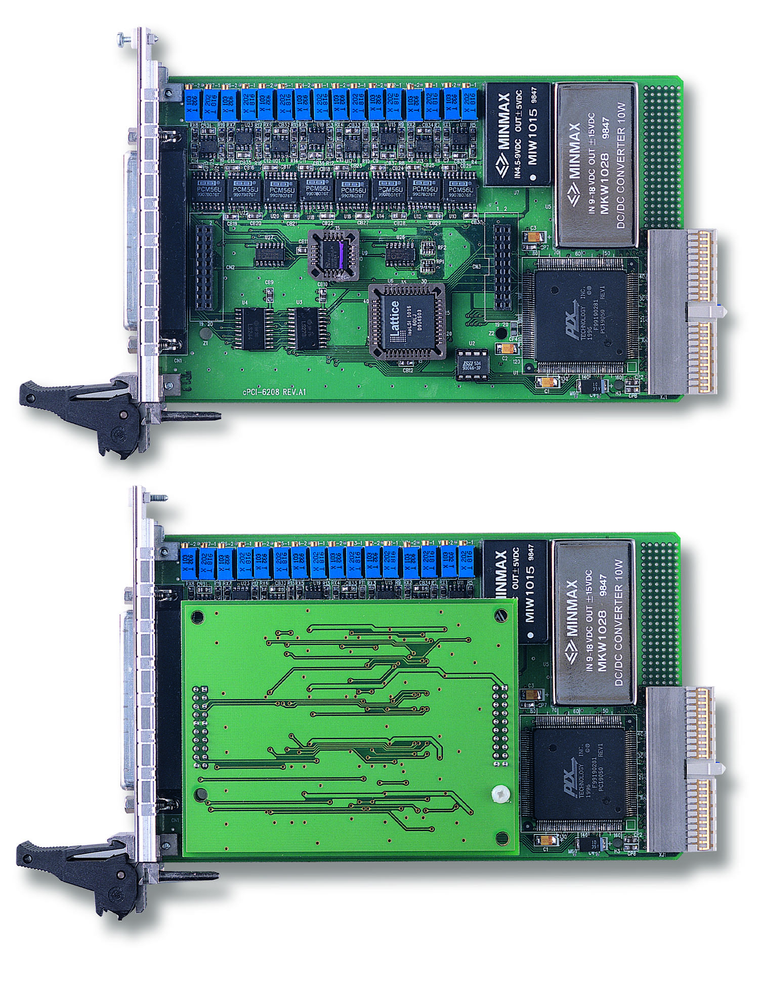
Comprehensive Product Summary: ADLINK cPCI‑6216V‑GL 16‑Channel 16‑Bit Analog Output CompactPCI Card
### 1. Product Overview
Product Name: cPCI‑6216V‑GL
Model: cPCI‑6216V‑GL
Series: 6208/6216‑GL Series (Multi‑Channel Analog Output Cards)
Article Number: cPCI‑6216V‑GL
Manufacturer: ADLINK Technology Inc.
Form Factor: 3U Eurocard, CompactPCI compliant (PICMG 2.0 R2.1)
Product Type: 16‑Channel, 16‑Bit Analog Voltage Output Module (±10 V)
The ADLINK cPCI‑6216V‑GL is a high‑precision, high‑density analog output card designed for CompactPCI systems. It provides 16 independent 16‑bit digital‑to‑analog (D/A) output channels with bipolar ±10 V ranges and up to ±5 mA drive capability per channel. The module is engineered for industrial automation, process control, signal generation, and servo control applications requiring deterministic analog output performance and CompactPCI integration.
### 2. Key Features
- High‑Resolution Analog Output:
16‑bit D/A resolution with guaranteed 15‑bit monotonicity for precise voltage generation.
- Multi‑Channel Output:
16 independent voltage output channels (±10 V range) with simultaneous update capability.
- CompactPCI Bus Interface:
Fully compliant with PICMG 2.0 R2.1 CompactPCI standard, 3U Eurocard form factor (100 × 160 mm).
- Fast Output Response:
Typical slew rate of 26 V/µs and settling time of 130 µs for a 20 V step.
- High Accuracy:
Gain error ±0.2 % FSR (max), DNL ±1 LSB (typical), monotonic 15 bits.
- Integrated DC/DC Converter:
Provides isolated power for stable analog performance.
- Digital I/O Support:
4 TTL digital inputs and 4 TTL digital outputs for auxiliary control and synchronization.
- Plug‑and‑Play Configuration:
Automatic resource allocation via PCI PnP BIOS; no manual jumper settings required.
- Software & OS Support:
Drivers and SDKs for Windows 7/8 (x86/x64) and Linux; compatible with LabVIEW™, MATLAB®, C/C++, Visual Basic, and Visual Studio .NET.
- Calibration & Utility Tools:
Factory‑calibrated with precision DMM; includes DOS‑based utility for function testing and calibration.
- Industrial‑Grade Design:
Operating temperature 0 °C – 50 °C, humidity 5 % – 95 % (non‑condensing).
### 3. Technical Specifications
Analog Voltage Output
- Channels: 16 voltage outputs
- Resolution: 16 bits (15‑bit guaranteed monotonicity)
- Output Range: ±10 V bipolar
- Output Drive: ±5 mA max per channel
- Slew Rate: 26 V/µs typical
- Settling Time: 130 µs typical (20 V step)
- Gain Error: ±0.2 % max
- Differential Non‑Linearity (DNL): ±1 LSB typical
- Output Initial State: 0 V after reset/power‑on
- Data Transfer: Programmed I/O
Digital I/O
- Channels: 4 inputs + 4 outputs (TTL compatible, 5 V logic)
- Input Voltage: Low ≤ 0.8 V, High ≥ 2.0 V
- Output Voltage: Low ≤ 0.4 V, High ≥ 2.4 V
- Drive Capability: Sink 8 mA @ 0.5 V, Source 0.4 mA @ 2.7 V
Electrical & Power Requirements
- +5 V DC: 1 A typical
- +12 V DC: 300 mA typical
- Power Consumption: Approx. 8.6 W total
Physical Characteristics
- Dimensions (PCB only): 160 mm × 100 mm (6.24 in × 3.9 in)
- Weight: Approx. 200 g (typical)
- Connector: One 37‑pin D‑sub female (CN1)
- Form Factor: 3U Eurocard, CompactPCI
Environmental Conditions
- Operating Temperature: 0 °C – 50 °C (32 °F – 122 °F)
- Storage Temperature: –20 °C – 80 °C (–4 °F – 176 °F)
- Relative Humidity: 5 % – 95 %, non‑condensing
### 4. Functionality
The cPCI‑6216V‑GL performs digital‑to‑analog conversion on 16 independent channels, each driven by a dedicated 16‑bit DAC (e.g., BB PCM56U or equivalent). Each channel can output a programmable voltage between –10 V and +10 V, suitable for controlling actuators, generating reference signals, or driving analog instrumentation.
Operation Principle:
Digital data written via the CompactPCI bus is converted to analog voltage outputs. The card’s onboard DACs and DC/DC converter ensure stable, low‑noise analog performance. The device supports programmed I/O data transfer and provides status registers for synchronization and monitoring.
Use Cases & Applications:
- Industrial process control and automation
- Servo and motion control systems
- Signal generation and waveform synthesis
- Reference voltage or bias generation
- Automated test equipment (ATE)
- SCADA/HMI integration and laboratory instrumentation
Compatibility:
- CompactPCI 3U systems compliant with PICMG 2.0 R2.1
- Supported OS: Windows 7/8 (x86/x64), Linux
- Supported APIs: DAQPilot, PCIS‑DASK, LabVIEW™, MATLAB®, VEE™, ActiveX
### 5. Components & Accessories
Included Items:
- cPCI‑6216V‑GL card
- ADLINK All‑in‑One Software CD (drivers, SDKs, utilities)
- User’s Manual (PDF and printed)
Optional Accessories:
- DIN‑37D‑01: DIN‑rail terminal board with one 37‑pin D‑sub connector (cables not included)
- ACLD‑9137‑01: General‑purpose terminal board with 37‑pin D‑sub male connector
- ACLD‑9137F‑01: General‑purpose terminal board with 37‑pin D‑sub female connector
- ACL‑10137‑1MM: 37‑pin D‑sub male/male cable, 1 m
- ACL‑10137‑1MF: 37‑pin D‑sub male/female cable, 1 m
Connector Pinout:
- Analog outputs: V0 – V15 and A.GND (common analog ground)
- Digital I/O: DI0 – DI3, DO0 – DO3
### 6. Installation & Setup
Requirements:
- CompactPCI chassis with available 3U slot
- Host system supporting PICMG 2.0 R2.1 bus
- +5 V and +12 V power rails
Installation Steps:
1. Power off the CompactPCI system and all peripherals.
2. Observe ESD precautions (use grounded wrist strap and anti‑static mat).
3. Insert the cPCI‑6216V‑GL into a 3U CompactPCI slot.
4. Secure the module using the front‑panel screws.
5. Connect the 37‑pin D‑sub cable to the terminal board or external device.
6. Power on the system; the BIOS automatically assigns resources (PnP).
7. Install ADLINK DAQPilot or PCIS‑DASK drivers from the All‑in‑One CD.
8. Verify operation using the included 6208/6216 utility or DAQMaster software.
Configuration:
No manual jumper settings are required. All base addresses and interrupts are automatically configured by the PCI PnP BIOS.
### 7. Performance & Capabilities
Analog Output Performance:
- 16 simultaneous channels with independent update control
- ±10 V bipolar range, ±5 mA drive per channel
- 16‑bit DAC resolution (1 LSB ≈ 0.00031 V)
- Typical linearity: ±2.5 LSB INL, ±1.5 LSB DNL
- Output accuracy: Gain error ≤ 0.2 %, Offset error ≤ 0.0005 % FSR
- Update rate limited by 2.2 µs per channel transfer
Digital I/O Performance:
- TTL 5 V logic compatible
- 4 inputs + 4 outputs for control, triggering, or status monitoring
Efficiency & Reliability:
- Low power consumption (approx. 8.6 W)
- Stable operation across industrial temperature range
- Factory calibration ensures long‑term accuracy
Limitations:
- No rear I/O support (for rear I/O use cPCI‑6216V/R‑GL variant)
- Programmed I/O only (no DMA transfer)
- Output current limited to ±5 mA per channel
### 8. Standards & Compliance
- CompactPCI Compliance: PICMG 2.0 R2.1
- Bus Interface: 32‑bit CompactPCI slave device
- Electrical Safety: Designed for industrial environments (0 – 50 °C operation)
- EMC/ESD: Meets standard industrial immunity and emission requirements
- Software Standards: Supports Windows and Linux drivers, LabVIEW™, MATLAB®, ActiveX interfaces
- RoHS/CE: Compliant with ADLINK’s environmental and safety directives
### 9. Additional Information
Calibration & Maintenance:
Each cPCI‑6216V‑GL is factory‑calibrated using a 6½‑digit precision DMM to minimize gain and offset errors. Calibration data is stored in onboard Flash memory. ADLINK recommends recalibration every 12 months to maintain accuracy.
Warranty:
Standard ADLINK limited warranty (typically 2 years) covering manufacturing defects and hardware failures under normal use.
Technical Support & Service:
ADLINK provides global technical support through regional offices in Taiwan, USA, China, Europe, Japan, Korea, Singapore, and India.
Email: service@adlinktech.com | Website: [www.adlinktech.com](https://www.adlinktech.com)
Software Updates:
Driver and SDK updates available via ADLINK website (DAQPilot, DAQMaster, PCIS‑DASK, LabVIEW™, MATLAB® adapters).
Maintenance Recommendations:
- Operate within specified environmental limits.
- Avoid exposure to moisture, dust, or vibration.
- Use anti‑static handling procedures during installation or service.
- Periodically inspect connectors and cables for wear or damage.
### Summary
The ADLINK cPCI‑6216V‑GL is a robust, high‑precision 16‑channel 16‑bit analog output module for CompactPCI systems. It delivers ±10 V bipolar outputs with excellent accuracy, fast response, and industrial‑grade reliability. With integrated digital I/O, broad software support, and factory calibration, it is ideal for automation, test and measurement, and control applications requiring deterministic analog signal generation within a CompactPCI architecture.

### 1. Product Overview
Product Name: cPCI‑6216V‑GL
Model: cPCI‑6216V‑GL
Series: 6208/6216‑GL Series (Multi‑Channel Analog Output Cards)
Article Number: cPCI‑6216V‑GL
Manufacturer: ADLINK Technology Inc.
Form Factor: 3U Eurocard, CompactPCI compliant (PICMG 2.0 R2.1)
Product Type: 16‑Channel, 16‑Bit Analog Voltage Output Module (±10 V)
The ADLINK cPCI‑6216V‑GL is a high‑precision, high‑density analog output card designed for CompactPCI systems. It provides 16 independent 16‑bit digital‑to‑analog (D/A) output channels with bipolar ±10 V ranges and up to ±5 mA drive capability per channel. The module is engineered for industrial automation, process control, signal generation, and servo control applications requiring deterministic analog output performance and CompactPCI integration.
### 2. Key Features
- High‑Resolution Analog Output:
16‑bit D/A resolution with guaranteed 15‑bit monotonicity for precise voltage generation.
- Multi‑Channel Output:
16 independent voltage output channels (±10 V range) with simultaneous update capability.
- CompactPCI Bus Interface:
Fully compliant with PICMG 2.0 R2.1 CompactPCI standard, 3U Eurocard form factor (100 × 160 mm).
- Fast Output Response:
Typical slew rate of 26 V/µs and settling time of 130 µs for a 20 V step.
- High Accuracy:
Gain error ±0.2 % FSR (max), DNL ±1 LSB (typical), monotonic 15 bits.
- Integrated DC/DC Converter:
Provides isolated power for stable analog performance.
- Digital I/O Support:
4 TTL digital inputs and 4 TTL digital outputs for auxiliary control and synchronization.
- Plug‑and‑Play Configuration:
Automatic resource allocation via PCI PnP BIOS; no manual jumper settings required.
- Software & OS Support:
Drivers and SDKs for Windows 7/8 (x86/x64) and Linux; compatible with LabVIEW™, MATLAB®, C/C++, Visual Basic, and Visual Studio .NET.
- Calibration & Utility Tools:
Factory‑calibrated with precision DMM; includes DOS‑based utility for function testing and calibration.
- Industrial‑Grade Design:
Operating temperature 0 °C – 50 °C, humidity 5 % – 95 % (non‑condensing).
### 3. Technical Specifications
Analog Voltage Output
- Channels: 16 voltage outputs
- Resolution: 16 bits (15‑bit guaranteed monotonicity)
- Output Range: ±10 V bipolar
- Output Drive: ±5 mA max per channel
- Slew Rate: 26 V/µs typical
- Settling Time: 130 µs typical (20 V step)
- Gain Error: ±0.2 % max
- Differential Non‑Linearity (DNL): ±1 LSB typical
- Output Initial State: 0 V after reset/power‑on
- Data Transfer: Programmed I/O
Digital I/O
- Channels: 4 inputs + 4 outputs (TTL compatible, 5 V logic)
- Input Voltage: Low ≤ 0.8 V, High ≥ 2.0 V
- Output Voltage: Low ≤ 0.4 V, High ≥ 2.4 V
- Drive Capability: Sink 8 mA @ 0.5 V, Source 0.4 mA @ 2.7 V
Electrical & Power Requirements
- +5 V DC: 1 A typical
- +12 V DC: 300 mA typical
- Power Consumption: Approx. 8.6 W total
Physical Characteristics
- Dimensions (PCB only): 160 mm × 100 mm (6.24 in × 3.9 in)
- Weight: Approx. 200 g (typical)
- Connector: One 37‑pin D‑sub female (CN1)
- Form Factor: 3U Eurocard, CompactPCI
Environmental Conditions
- Operating Temperature: 0 °C – 50 °C (32 °F – 122 °F)
- Storage Temperature: –20 °C – 80 °C (–4 °F – 176 °F)
- Relative Humidity: 5 % – 95 %, non‑condensing
### 4. Functionality
The cPCI‑6216V‑GL performs digital‑to‑analog conversion on 16 independent channels, each driven by a dedicated 16‑bit DAC (e.g., BB PCM56U or equivalent). Each channel can output a programmable voltage between –10 V and +10 V, suitable for controlling actuators, generating reference signals, or driving analog instrumentation.
Operation Principle:
Digital data written via the CompactPCI bus is converted to analog voltage outputs. The card’s onboard DACs and DC/DC converter ensure stable, low‑noise analog performance. The device supports programmed I/O data transfer and provides status registers for synchronization and monitoring.
Use Cases & Applications:
- Industrial process control and automation
- Servo and motion control systems
- Signal generation and waveform synthesis
- Reference voltage or bias generation
- Automated test equipment (ATE)
- SCADA/HMI integration and laboratory instrumentation
Compatibility:
- CompactPCI 3U systems compliant with PICMG 2.0 R2.1
- Supported OS: Windows 7/8 (x86/x64), Linux
- Supported APIs: DAQPilot, PCIS‑DASK, LabVIEW™, MATLAB®, VEE™, ActiveX
### 5. Components & Accessories
Included Items:
- cPCI‑6216V‑GL card
- ADLINK All‑in‑One Software CD (drivers, SDKs, utilities)
- User’s Manual (PDF and printed)
Optional Accessories:
- DIN‑37D‑01: DIN‑rail terminal board with one 37‑pin D‑sub connector (cables not included)
- ACLD‑9137‑01: General‑purpose terminal board with 37‑pin D‑sub male connector
- ACLD‑9137F‑01: General‑purpose terminal board with 37‑pin D‑sub female connector
- ACL‑10137‑1MM: 37‑pin D‑sub male/male cable, 1 m
- ACL‑10137‑1MF: 37‑pin D‑sub male/female cable, 1 m
Connector Pinout:
- Analog outputs: V0 – V15 and A.GND (common analog ground)
- Digital I/O: DI0 – DI3, DO0 – DO3
### 6. Installation & Setup
Requirements:
- CompactPCI chassis with available 3U slot
- Host system supporting PICMG 2.0 R2.1 bus
- +5 V and +12 V power rails
Installation Steps:
1. Power off the CompactPCI system and all peripherals.
2. Observe ESD precautions (use grounded wrist strap and anti‑static mat).
3. Insert the cPCI‑6216V‑GL into a 3U CompactPCI slot.
4. Secure the module using the front‑panel screws.
5. Connect the 37‑pin D‑sub cable to the terminal board or external device.
6. Power on the system; the BIOS automatically assigns resources (PnP).
7. Install ADLINK DAQPilot or PCIS‑DASK drivers from the All‑in‑One CD.
8. Verify operation using the included 6208/6216 utility or DAQMaster software.
Configuration:
No manual jumper settings are required. All base addresses and interrupts are automatically configured by the PCI PnP BIOS.
### 7. Performance & Capabilities
Analog Output Performance:
- 16 simultaneous channels with independent update control
- ±10 V bipolar range, ±5 mA drive per channel
- 16‑bit DAC resolution (1 LSB ≈ 0.00031 V)
- Typical linearity: ±2.5 LSB INL, ±1.5 LSB DNL
- Output accuracy: Gain error ≤ 0.2 %, Offset error ≤ 0.0005 % FSR
- Update rate limited by 2.2 µs per channel transfer
Digital I/O Performance:
- TTL 5 V logic compatible
- 4 inputs + 4 outputs for control, triggering, or status monitoring
Efficiency & Reliability:
- Low power consumption (approx. 8.6 W)
- Stable operation across industrial temperature range
- Factory calibration ensures long‑term accuracy
Limitations:
- No rear I/O support (for rear I/O use cPCI‑6216V/R‑GL variant)
- Programmed I/O only (no DMA transfer)
- Output current limited to ±5 mA per channel
### 8. Standards & Compliance
- CompactPCI Compliance: PICMG 2.0 R2.1
- Bus Interface: 32‑bit CompactPCI slave device
- Electrical Safety: Designed for industrial environments (0 – 50 °C operation)
- EMC/ESD: Meets standard industrial immunity and emission requirements
- Software Standards: Supports Windows and Linux drivers, LabVIEW™, MATLAB®, ActiveX interfaces
- RoHS/CE: Compliant with ADLINK’s environmental and safety directives
### 9. Additional Information
Calibration & Maintenance:
Each cPCI‑6216V‑GL is factory‑calibrated using a 6½‑digit precision DMM to minimize gain and offset errors. Calibration data is stored in onboard Flash memory. ADLINK recommends recalibration every 12 months to maintain accuracy.
Warranty:
Standard ADLINK limited warranty (typically 2 years) covering manufacturing defects and hardware failures under normal use.
Technical Support & Service:
ADLINK provides global technical support through regional offices in Taiwan, USA, China, Europe, Japan, Korea, Singapore, and India.
Email: service@adlinktech.com | Website: [www.adlinktech.com](https://www.adlinktech.com)
Software Updates:
Driver and SDK updates available via ADLINK website (DAQPilot, DAQMaster, PCIS‑DASK, LabVIEW™, MATLAB® adapters).
Maintenance Recommendations:
- Operate within specified environmental limits.
- Avoid exposure to moisture, dust, or vibration.
- Use anti‑static handling procedures during installation or service.
- Periodically inspect connectors and cables for wear or damage.
### Summary
The ADLINK cPCI‑6216V‑GL is a robust, high‑precision 16‑channel 16‑bit analog output module for CompactPCI systems. It delivers ±10 V bipolar outputs with excellent accuracy, fast response, and industrial‑grade reliability. With integrated digital I/O, broad software support, and factory calibration, it is ideal for automation, test and measurement, and control applications requiring deterministic analog signal generation within a CompactPCI architecture.
- DIN-37D-01 - 37pin D-type panel DIN rail w/o cable