LOOKING FOR THE RIGHT
INDUSTRIAL SOLUTION?
Discover embedded, communication and automation solutions tailored to your application.
- Universal Connectivity: Supports both input and output configurations through opto‑isolated or relay‑driven channels.
- Opto‑22 Compatibility: 50‑pin connectors conform to the Opto‑22 standard, ensuring direct interfacing with ADLINK DAQ cards such as ACL‑7122, ACL‑7124, PET‑48DIO, PCI‑7248, and PCI‑7296.
- Multiple Configurations: Available in several variants:
- TB‑24P: 24 opto‑isolated digital inputs.
- TB‑24R: 24 relay outputs.
- TB‑16P8R: 16 opto‑isolated inputs + 8 relay outputs.
- DIN‑24P: 24 opto‑isolated inputs with DIN‑rail mounting.
- DIN‑24R: 24 relay outputs with DIN‑rail mounting.
- DIN‑24G: 24‑position I/O module rack for modular expansion.
- LED Status Indicators: 24 channel‑mapped LEDs provide real‑time visual feedback of input or output states.
- High Isolation: Up to 2500 V DC (TB‑24P) or 5000 Vrms (DIN‑24P) isolation between field and logic sides.
- Relay Switching Capability: SPDT relays rated up to 250 V AC / 220 V DC, 2 A switching current, 3 A carrying current.
- Flexible Power Options: 12 V DC or 24 V DC coil voltage versions available.
- Breadboard Area: Integrated prototyping section for custom circuitry or signal conditioning.
- Compact and Modular Design: 125 mm × 73 mm PCB with detachable terminal blocks for easy wiring.
- DIN‑Rail Mounting (DIN Series): Industrial‑grade mechanical design for control cabinets.
- Comprehensive LED Color Coding: Green, yellow, and red LEDs distinguish channel groups (A, B, C).
- Jumper‑Selectable Input Modes: Configurable for dry contact or photo‑coupler input operation.
- Full Compatibility with ADLINK NuDAQ and NuDAM Systems.
- Opto‑22 Compatibility: 50‑pin connectors conform to the Opto‑22 standard, ensuring direct interfacing with ADLINK DAQ cards such as ACL‑7122, ACL‑7124, PET‑48DIO, PCI‑7248, and PCI‑7296.
- Multiple Configurations: Available in several variants:
- TB‑24P: 24 opto‑isolated digital inputs.
- TB‑24R: 24 relay outputs.
- TB‑16P8R: 16 opto‑isolated inputs + 8 relay outputs.
- DIN‑24P: 24 opto‑isolated inputs with DIN‑rail mounting.
- DIN‑24R: 24 relay outputs with DIN‑rail mounting.
- DIN‑24G: 24‑position I/O module rack for modular expansion.
- LED Status Indicators: 24 channel‑mapped LEDs provide real‑time visual feedback of input or output states.
- High Isolation: Up to 2500 V DC (TB‑24P) or 5000 Vrms (DIN‑24P) isolation between field and logic sides.
- Relay Switching Capability: SPDT relays rated up to 250 V AC / 220 V DC, 2 A switching current, 3 A carrying current.
- Flexible Power Options: 12 V DC or 24 V DC coil voltage versions available.
- Breadboard Area: Integrated prototyping section for custom circuitry or signal conditioning.
- Compact and Modular Design: 125 mm × 73 mm PCB with detachable terminal blocks for easy wiring.
- DIN‑Rail Mounting (DIN Series): Industrial‑grade mechanical design for control cabinets.
- Comprehensive LED Color Coding: Green, yellow, and red LEDs distinguish channel groups (A, B, C).
- Jumper‑Selectable Input Modes: Configurable for dry contact or photo‑coupler input operation.
- Full Compatibility with ADLINK NuDAQ and NuDAM Systems.
Comprehensive Product Summary: ADLINK TB‑24 Universal Screw Terminal Panel with 1.5 m Cable
### 1. Product Overview
Product Name: TB‑24 Universal Screw Terminal Panel
Model: TB‑24
Series: TB‑24P / TB‑24R / TB‑16P8R / DIN‑24P / DIN‑24R / DIN‑24G Terminal Board Series
Article Number: TB‑24
Manufacturer: ADLINK Technology Inc.
Manufacturer Address: 9F, No. 166, Jian Yi Road, Chungho City, Taipei 235, Taiwan, R.O.C.
Website: [www.adlink.com.tw](http://www.adlink.com.tw)
Support Contacts:
- Sales & Service: service@adlink.com.tw
- Technical Support (NuDAQ): nudaq@adlink.com.tw
- NuDAM: nudam@adlink.com.tw
- NuIPC: nuipc@adlink.com.tw
- NuPRO: nupro@adlink.com.tw
- Software: sw@adlink.com.tw
- AMB: amb@adlink.com.tw
Telephone: +886‑2‑82265877 Fax: +886‑2‑82265717
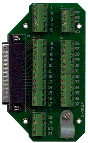
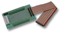
The TB‑24 is a universal screw terminal panel designed for general‑purpose digital I/O interfacing. It provides a 1.5 m flat cable terminated with dual 50‑pin connectors and DB‑37 male/female connectors, enabling flexible connection between data acquisition (DAQ) boards, relay modules, and external devices. The board includes two 2×25 screw clamp terminal blocks and a breadboard area for prototyping. Its compact footprint (125 × 73 mm) makes it suitable for laboratory, industrial, and embedded control environments.
### 2. Key Features
- Universal Connectivity: Supports both input and output configurations through opto‑isolated or relay‑driven channels.
- Opto‑22 Compatibility: 50‑pin connectors conform to the Opto‑22 standard, ensuring direct interfacing with ADLINK DAQ cards such as ACL‑7122, ACL‑7124, PET‑48DIO, PCI‑7248, and PCI‑7296.
- Multiple Configurations: Available in several variants:
- TB‑24P: 24 opto‑isolated digital inputs.
- TB‑24R: 24 relay outputs.
- TB‑16P8R: 16 opto‑isolated inputs + 8 relay outputs.
- DIN‑24P: 24 opto‑isolated inputs with DIN‑rail mounting.
- DIN‑24R: 24 relay outputs with DIN‑rail mounting.
- DIN‑24G: 24‑position I/O module rack for modular expansion.
- LED Status Indicators: 24 channel‑mapped LEDs provide real‑time visual feedback of input or output states.
- High Isolation: Up to 2500 V DC (TB‑24P) or 5000 Vrms (DIN‑24P) isolation between field and logic sides.
- Relay Switching Capability: SPDT relays rated up to 250 V AC / 220 V DC, 2 A switching current, 3 A carrying current.
- Flexible Power Options: 12 V DC or 24 V DC coil voltage versions available.
- Breadboard Area: Integrated prototyping section for custom circuitry or signal conditioning.
- Compact and Modular Design: 125 mm × 73 mm PCB with detachable terminal blocks for easy wiring.
- DIN‑Rail Mounting (DIN Series): Industrial‑grade mechanical design for control cabinets.
- Comprehensive LED Color Coding: Green, yellow, and red LEDs distinguish channel groups (A, B, C).
- Jumper‑Selectable Input Modes: Configurable for dry contact or photo‑coupler input operation.
- Full Compatibility with ADLINK NuDAQ and NuDAM Systems.
### 3. Technical Specifications
Physical Characteristics
- Dimensions: 125 mm (L) × 73 mm (W)
- Cable Length: 1.5 m flat ribbon cable
- Connectors:
- 2 × 50‑pin Opto‑22 compatible headers
- 1 × DB‑37 female connector
- 1 × DB‑37 male connector
- 2 × (2 × 25) screw clamp terminal blocks
- Material: FR‑4 PCB, tin‑plated copper traces, plastic terminal housings
- Mounting: Panel or DIN‑rail (DIN models)
Electrical Characteristics (Input Boards)
- Logic Input Low Voltage: < 0.8 V DC
- Logic Input High Voltage: +3 V DC to +24 V DC
- Input Current: 6.3 mA to 50 mA
- Isolation Voltage: 2500 V DC (TB‑24P) / 5000 Vrms (DIN‑24P)
- Input Indication: 24 LEDs (green/yellow/red)
Electrical Characteristics (Relay Boards)
- Relay Type: High‑sensitivity miniature SPDT relay, 1500 V FCC surge withstand
- Contact Rating:
- Max switching power: 60 W / 125 VA
- Max switching voltage: 220 V DC / 250 V AC
- Max switching current: 2 A DC or AC
- Max carrying current: 3 A DC or AC
- UL/CSA ratings: 0.6 A @ 125 V AC, 0.6 A @ 110 V DC, 2 A @ 30 V DC
- Coil Voltage Options: 12 V DC (TB‑24R/12, TB‑16P8R/12, DIN‑24R/12) or 24 V DC (TB‑24R/24, TB‑16P8R/24, DIN‑24R/24)
- Power Supply Connector: Dedicated CN5/CN9 terminal for external DC supply
Environmental
- Operating Temperature: 0 °C to +50 °C (typical)
- Storage Temperature: –20 °C to +70 °C
- Relative Humidity: 10 % – 90 %, non‑condensing
### 4. Functionality
The TB‑24 series serves as an interface terminal board between digital I/O cards and field devices. It simplifies wiring by converting high‑density ribbon or SCSI connectors into screw terminals for sensors, switches, relays, and actuators.
Operation Principles:
- Input Boards (TB‑24P, DIN‑24P): Each channel uses an opto‑isolator to protect the host system from voltage transients. Logic “1” corresponds to a high‑level input (+3 V to +24 V DC), lighting the corresponding LED. Logic “0” (< 0.8 V DC) turns the LED off.
- Output Boards (TB‑24R, DIN‑24R): Each channel drives a relay coil through the control signal from the DAQ card. The relay provides isolated SPDT contacts for switching external loads.
- Mixed Board (TB‑16P8R): Combines 16 opto‑isolated inputs and 8 relay outputs, allowing bidirectional control in compact systems.
- DIN‑24G: Provides 24 mounting positions for plug‑in I/O modules (AC/DC input or output types), extending the flexibility of NuDAQ/NuDAM systems.
Typical Applications:
- Industrial automation and process control
- Laboratory instrumentation and test benches
- PLC and DAQ signal interfacing
- Machine monitoring and alarm systems
- Relay control of solenoids, lamps, and motors
- Sensor input collection (limit switches, proximity sensors, etc.)
Compatibility:
- Fully compatible with ADLINK digital I/O cards: ACL‑7122, ACL‑7124, PET‑48DIO, PCI‑7248, PCI‑7296, ND‑6058, and other Opto‑22‑style interfaces.
- Supports both 50‑pin flat‑cable and 50‑pin SCSI‑type connections.
### 5. Components & Accessories
Included Components:
- TB‑24 terminal board (selected variant)
- 1.5 m 50‑pin flat ribbon cable
- DB‑37 male and female connectors
- Two 2×25 screw terminal blocks
- Breadboard/prototyping area
- LED indicators for each channel
Optional Accessories:
- DIN‑rail mounting kit (for DIN models)
- Additional 50‑pin ribbon cables
- External DC power supply (12 V or 24 V)
- Replacement relays (DSIE‑S‑DC12V / DSIE‑S‑DC24V)
- Opto‑22 compatible I/O modules (for DIN‑24G)
Connectors Overview:
- CN1–CN4 (TB‑24P/R): Terminal blocks for channel wiring
- CN5/CN6: 50‑pin Opto‑22 compatible connectors
- CN7/CN8 (DIN‑24P): Terminal blocks for input channels
- CN9 (DIN‑24R): Power input terminal
- J1/J2 (DIN‑24R): Output terminal blocks
- CN6/CN7 (DIN‑24R): Opto‑22 and SCSI connectors
### 6. Installation & Setup
Requirements:
- Compatible ADLINK DAQ or DIO card with 50‑pin Opto‑22 or SCSI interface
- External DC power supply (12 V or 24 V depending on model)
- Mounting surface or DIN‑rail (for DIN models)
Installation Steps:
1. Mounting: Secure the TB‑24 board on a flat surface or DIN‑rail using the provided mounting holes or clips.
2. Power Connection: Connect the external DC supply to CN5 (TB‑24R) or CN9 (DIN‑24R). Observe polarity and voltage rating.
3. Signal Connection:
- For input boards, connect sensors or switches to the screw terminals (CN1–CN4 or CN7–CN8).
- For output boards, connect load devices to the relay terminals (Common, Normally Open, Normally Closed).
4. Host Interface: Attach the 50‑pin ribbon cable between the TB‑24 and the DAQ card. Ensure correct orientation (pin 1 alignment).
5. Jumper Configuration:
- Input boards: Set jumpers for dry contact or photo‑coupler mode.
- Mixed boards: Configure JP8–JP23 for input type selection.
6. Verification: Power on the system and verify LED indicators correspond to input/output states.
Configuration Notes:
- For TB‑16P8R, set the DAQ card I/O mode to Mode 7 for proper port mapping (Port A = Relay Output; Ports B & C = Opto‑isolated Input).
- Ensure isolation barriers are maintained; do not exceed rated voltages.
### 7. Performance & Capabilities
Input Performance:
- Fast response opto‑isolators suitable for digital signal acquisition up to typical DAQ sampling rates.
- High noise immunity due to optical isolation and pull‑up resistor network (4.7 kΩ).
- LED indication latency negligible for human observation (< 10 ms).
Output Performance:
- Mechanical relay switching time typically 10–15 ms.
- Capable of switching both AC and DC loads up to 250 V AC or 220 V DC.
- Contact endurance rated for thousands of operations under nominal load.
- Coil power consumption approximately 0.4 W (12 V) / 0.8 W (24 V).
Capacity & Scalability:
- 24 channels per board; multiple boards can be cascaded for higher channel counts.
- DIN‑24G supports 24 modular positions for flexible I/O configuration.
Efficiency & Limitations:
- Designed for low‑to‑medium speed control (mechanical relay limitation).
- Not suitable for high‑frequency switching or analog signal transmission.
- Isolation and relay ratings must not be exceeded to maintain safety and reliability.
### 8. Standards & Compliance
- Electrical Safety: Isolation up to 2500 V DC / 5000 Vrms depending on model.
- Relay Certification: UL/CSA recognized miniature relays.
- Interface Standard: Opto‑22 compatible 50‑pin pinout.
- Environmental Compliance: Designed for industrial temperature and humidity ranges.
- Quality Assurance: Manufactured under ADLINK’s ISO‑certified production processes.
- Regulatory Notes: Product specifications subject to change without notice to improve reliability and design.
### 9. Additional Information
Warranty:
ADLINK provides a one‑year limited warranty from the confirmed date of purchase. The warranty covers defects in materials and workmanship under normal use. ADLINK will repair or replace defective units at its discretion.
Warranty Exclusions:
- Damage due to misuse, modification, or operation beyond specifications.
- Units with removed or altered serial numbers.
- Consequential damages are excluded; liability limited to original purchase price.
Service Procedure:
- Return equipment postage‑prepaid and securely packaged.
- Include proof of purchase and detailed problem description.
- Contact ADLINK service department for RMA authorization prior to shipment.
Maintenance:
- Periodically inspect terminal screws for tightness.
- Avoid exposure to excessive dust, moisture, or vibration.
- Replace relays only with identical rated components.
Support & Updates:
- Technical documentation and driver updates available at [www.adlink.com.tw](http://www.adlink.com.tw).
- Firmware and software support provided through NuDAQ and NuDAM technical channels.
### Summary
The ADLINK TB‑24 Universal Screw Terminal Panel is a versatile, high‑reliability interface solution for digital I/O expansion. Its modular design supports multiple configurations—ranging from opto‑isolated input boards to relay output and mixed I/O boards—making it adaptable to a wide range of industrial and laboratory applications. With robust electrical isolation, Opto‑22 compatibility, and clear LED indication, the TB‑24 series simplifies wiring, enhances safety, and ensures dependable signal interfacing between control systems and field devices.
Whether used as a standalone terminal panel or integrated into a DIN‑rail‑mounted control system, the TB‑24 family exemplifies ADLINK’s commitment to precision engineering, flexibility, and long‑term reliability in data acquisition and automation environments.
### 1. Product Overview
Product Name: TB‑24 Universal Screw Terminal Panel
Model: TB‑24
Series: TB‑24P / TB‑24R / TB‑16P8R / DIN‑24P / DIN‑24R / DIN‑24G Terminal Board Series
Article Number: TB‑24
Manufacturer: ADLINK Technology Inc.
Manufacturer Address: 9F, No. 166, Jian Yi Road, Chungho City, Taipei 235, Taiwan, R.O.C.
Website: [www.adlink.com.tw](http://www.adlink.com.tw)
Support Contacts:
- Sales & Service: service@adlink.com.tw
- Technical Support (NuDAQ): nudaq@adlink.com.tw
- NuDAM: nudam@adlink.com.tw
- NuIPC: nuipc@adlink.com.tw
- NuPRO: nupro@adlink.com.tw
- Software: sw@adlink.com.tw
- AMB: amb@adlink.com.tw
Telephone: +886‑2‑82265877 Fax: +886‑2‑82265717
The TB‑24 is a universal screw terminal panel designed for general‑purpose digital I/O interfacing. It provides a 1.5 m flat cable terminated with dual 50‑pin connectors and DB‑37 male/female connectors, enabling flexible connection between data acquisition (DAQ) boards, relay modules, and external devices. The board includes two 2×25 screw clamp terminal blocks and a breadboard area for prototyping. Its compact footprint (125 × 73 mm) makes it suitable for laboratory, industrial, and embedded control environments.
### 2. Key Features
- Universal Connectivity: Supports both input and output configurations through opto‑isolated or relay‑driven channels.
- Opto‑22 Compatibility: 50‑pin connectors conform to the Opto‑22 standard, ensuring direct interfacing with ADLINK DAQ cards such as ACL‑7122, ACL‑7124, PET‑48DIO, PCI‑7248, and PCI‑7296.
- Multiple Configurations: Available in several variants:
- TB‑24P: 24 opto‑isolated digital inputs.
- TB‑24R: 24 relay outputs.
- TB‑16P8R: 16 opto‑isolated inputs + 8 relay outputs.
- DIN‑24P: 24 opto‑isolated inputs with DIN‑rail mounting.
- DIN‑24R: 24 relay outputs with DIN‑rail mounting.
- DIN‑24G: 24‑position I/O module rack for modular expansion.
- LED Status Indicators: 24 channel‑mapped LEDs provide real‑time visual feedback of input or output states.
- High Isolation: Up to 2500 V DC (TB‑24P) or 5000 Vrms (DIN‑24P) isolation between field and logic sides.
- Relay Switching Capability: SPDT relays rated up to 250 V AC / 220 V DC, 2 A switching current, 3 A carrying current.
- Flexible Power Options: 12 V DC or 24 V DC coil voltage versions available.
- Breadboard Area: Integrated prototyping section for custom circuitry or signal conditioning.
- Compact and Modular Design: 125 mm × 73 mm PCB with detachable terminal blocks for easy wiring.
- DIN‑Rail Mounting (DIN Series): Industrial‑grade mechanical design for control cabinets.
- Comprehensive LED Color Coding: Green, yellow, and red LEDs distinguish channel groups (A, B, C).
- Jumper‑Selectable Input Modes: Configurable for dry contact or photo‑coupler input operation.
- Full Compatibility with ADLINK NuDAQ and NuDAM Systems.
### 3. Technical Specifications
Physical Characteristics
- Dimensions: 125 mm (L) × 73 mm (W)
- Cable Length: 1.5 m flat ribbon cable
- Connectors:
- 2 × 50‑pin Opto‑22 compatible headers
- 1 × DB‑37 female connector
- 1 × DB‑37 male connector
- 2 × (2 × 25) screw clamp terminal blocks
- Material: FR‑4 PCB, tin‑plated copper traces, plastic terminal housings
- Mounting: Panel or DIN‑rail (DIN models)
Electrical Characteristics (Input Boards)
- Logic Input Low Voltage: < 0.8 V DC
- Logic Input High Voltage: +3 V DC to +24 V DC
- Input Current: 6.3 mA to 50 mA
- Isolation Voltage: 2500 V DC (TB‑24P) / 5000 Vrms (DIN‑24P)
- Input Indication: 24 LEDs (green/yellow/red)
Electrical Characteristics (Relay Boards)
- Relay Type: High‑sensitivity miniature SPDT relay, 1500 V FCC surge withstand
- Contact Rating:
- Max switching power: 60 W / 125 VA
- Max switching voltage: 220 V DC / 250 V AC
- Max switching current: 2 A DC or AC
- Max carrying current: 3 A DC or AC
- UL/CSA ratings: 0.6 A @ 125 V AC, 0.6 A @ 110 V DC, 2 A @ 30 V DC
- Coil Voltage Options: 12 V DC (TB‑24R/12, TB‑16P8R/12, DIN‑24R/12) or 24 V DC (TB‑24R/24, TB‑16P8R/24, DIN‑24R/24)
- Power Supply Connector: Dedicated CN5/CN9 terminal for external DC supply
Environmental
- Operating Temperature: 0 °C to +50 °C (typical)
- Storage Temperature: –20 °C to +70 °C
- Relative Humidity: 10 % – 90 %, non‑condensing
### 4. Functionality
The TB‑24 series serves as an interface terminal board between digital I/O cards and field devices. It simplifies wiring by converting high‑density ribbon or SCSI connectors into screw terminals for sensors, switches, relays, and actuators.
Operation Principles:
- Input Boards (TB‑24P, DIN‑24P): Each channel uses an opto‑isolator to protect the host system from voltage transients. Logic “1” corresponds to a high‑level input (+3 V to +24 V DC), lighting the corresponding LED. Logic “0” (< 0.8 V DC) turns the LED off.
- Output Boards (TB‑24R, DIN‑24R): Each channel drives a relay coil through the control signal from the DAQ card. The relay provides isolated SPDT contacts for switching external loads.
- Mixed Board (TB‑16P8R): Combines 16 opto‑isolated inputs and 8 relay outputs, allowing bidirectional control in compact systems.
- DIN‑24G: Provides 24 mounting positions for plug‑in I/O modules (AC/DC input or output types), extending the flexibility of NuDAQ/NuDAM systems.
Typical Applications:
- Industrial automation and process control
- Laboratory instrumentation and test benches
- PLC and DAQ signal interfacing
- Machine monitoring and alarm systems
- Relay control of solenoids, lamps, and motors
- Sensor input collection (limit switches, proximity sensors, etc.)
Compatibility:
- Fully compatible with ADLINK digital I/O cards: ACL‑7122, ACL‑7124, PET‑48DIO, PCI‑7248, PCI‑7296, ND‑6058, and other Opto‑22‑style interfaces.
- Supports both 50‑pin flat‑cable and 50‑pin SCSI‑type connections.
### 5. Components & Accessories
Included Components:
- TB‑24 terminal board (selected variant)
- 1.5 m 50‑pin flat ribbon cable
- DB‑37 male and female connectors
- Two 2×25 screw terminal blocks
- Breadboard/prototyping area
- LED indicators for each channel
Optional Accessories:
- DIN‑rail mounting kit (for DIN models)
- Additional 50‑pin ribbon cables
- External DC power supply (12 V or 24 V)
- Replacement relays (DSIE‑S‑DC12V / DSIE‑S‑DC24V)
- Opto‑22 compatible I/O modules (for DIN‑24G)
Connectors Overview:
- CN1–CN4 (TB‑24P/R): Terminal blocks for channel wiring
- CN5/CN6: 50‑pin Opto‑22 compatible connectors
- CN7/CN8 (DIN‑24P): Terminal blocks for input channels
- CN9 (DIN‑24R): Power input terminal
- J1/J2 (DIN‑24R): Output terminal blocks
- CN6/CN7 (DIN‑24R): Opto‑22 and SCSI connectors
### 6. Installation & Setup
Requirements:
- Compatible ADLINK DAQ or DIO card with 50‑pin Opto‑22 or SCSI interface
- External DC power supply (12 V or 24 V depending on model)
- Mounting surface or DIN‑rail (for DIN models)
Installation Steps:
1. Mounting: Secure the TB‑24 board on a flat surface or DIN‑rail using the provided mounting holes or clips.
2. Power Connection: Connect the external DC supply to CN5 (TB‑24R) or CN9 (DIN‑24R). Observe polarity and voltage rating.
3. Signal Connection:
- For input boards, connect sensors or switches to the screw terminals (CN1–CN4 or CN7–CN8).
- For output boards, connect load devices to the relay terminals (Common, Normally Open, Normally Closed).
4. Host Interface: Attach the 50‑pin ribbon cable between the TB‑24 and the DAQ card. Ensure correct orientation (pin 1 alignment).
5. Jumper Configuration:
- Input boards: Set jumpers for dry contact or photo‑coupler mode.
- Mixed boards: Configure JP8–JP23 for input type selection.
6. Verification: Power on the system and verify LED indicators correspond to input/output states.
Configuration Notes:
- For TB‑16P8R, set the DAQ card I/O mode to Mode 7 for proper port mapping (Port A = Relay Output; Ports B & C = Opto‑isolated Input).
- Ensure isolation barriers are maintained; do not exceed rated voltages.
### 7. Performance & Capabilities
Input Performance:
- Fast response opto‑isolators suitable for digital signal acquisition up to typical DAQ sampling rates.
- High noise immunity due to optical isolation and pull‑up resistor network (4.7 kΩ).
- LED indication latency negligible for human observation (< 10 ms).
Output Performance:
- Mechanical relay switching time typically 10–15 ms.
- Capable of switching both AC and DC loads up to 250 V AC or 220 V DC.
- Contact endurance rated for thousands of operations under nominal load.
- Coil power consumption approximately 0.4 W (12 V) / 0.8 W (24 V).
Capacity & Scalability:
- 24 channels per board; multiple boards can be cascaded for higher channel counts.
- DIN‑24G supports 24 modular positions for flexible I/O configuration.
Efficiency & Limitations:
- Designed for low‑to‑medium speed control (mechanical relay limitation).
- Not suitable for high‑frequency switching or analog signal transmission.
- Isolation and relay ratings must not be exceeded to maintain safety and reliability.
### 8. Standards & Compliance
- Electrical Safety: Isolation up to 2500 V DC / 5000 Vrms depending on model.
- Relay Certification: UL/CSA recognized miniature relays.
- Interface Standard: Opto‑22 compatible 50‑pin pinout.
- Environmental Compliance: Designed for industrial temperature and humidity ranges.
- Quality Assurance: Manufactured under ADLINK’s ISO‑certified production processes.
- Regulatory Notes: Product specifications subject to change without notice to improve reliability and design.
### 9. Additional Information
Warranty:
ADLINK provides a one‑year limited warranty from the confirmed date of purchase. The warranty covers defects in materials and workmanship under normal use. ADLINK will repair or replace defective units at its discretion.
Warranty Exclusions:
- Damage due to misuse, modification, or operation beyond specifications.
- Units with removed or altered serial numbers.
- Consequential damages are excluded; liability limited to original purchase price.
Service Procedure:
- Return equipment postage‑prepaid and securely packaged.
- Include proof of purchase and detailed problem description.
- Contact ADLINK service department for RMA authorization prior to shipment.
Maintenance:
- Periodically inspect terminal screws for tightness.
- Avoid exposure to excessive dust, moisture, or vibration.
- Replace relays only with identical rated components.
Support & Updates:
- Technical documentation and driver updates available at [www.adlink.com.tw](http://www.adlink.com.tw).
- Firmware and software support provided through NuDAQ and NuDAM technical channels.
### Summary
The ADLINK TB‑24 Universal Screw Terminal Panel is a versatile, high‑reliability interface solution for digital I/O expansion. Its modular design supports multiple configurations—ranging from opto‑isolated input boards to relay output and mixed I/O boards—making it adaptable to a wide range of industrial and laboratory applications. With robust electrical isolation, Opto‑22 compatibility, and clear LED indication, the TB‑24 series simplifies wiring, enhances safety, and ensures dependable signal interfacing between control systems and field devices.
Whether used as a standalone terminal panel or integrated into a DIN‑rail‑mounted control system, the TB‑24 family exemplifies ADLINK’s commitment to precision engineering, flexibility, and long‑term reliability in data acquisition and automation environments.
-
 TB-DIN24X Manual.PDF
Manual
TB-DIN24X Manual.PDF
Manual
No accessories available.