SUCHEN SIE DIE PASSENDE
INDUSTRIELLE LÖSUNG?
Entdecken Sie Embedded-, Kommunikations- und Automatisierungslösungen für Ihre Anwendung.
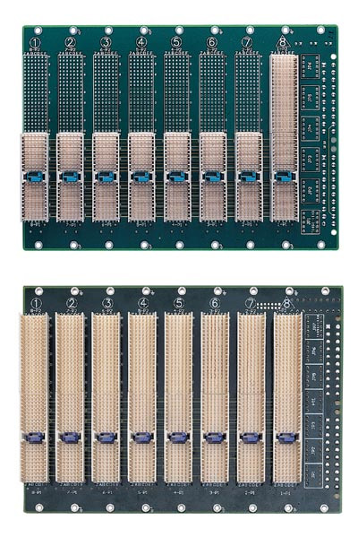
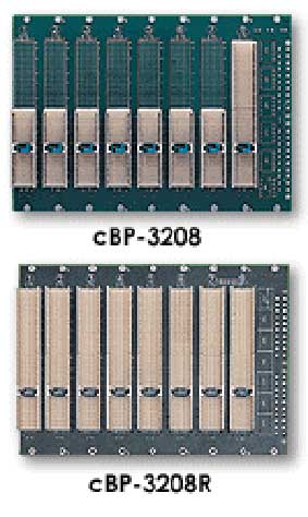
cBP-3206R
cPCI 6 slot 32bit backplane rear IO ATX
688,00 EUR
inkl. Umsatzsteuer 818,72 EUR
- CompactPCI Compliance: Fully compliant with PICMG 2.0 R2.1 CompactPCI specification, ensuring interoperability with standard CompactPCI CPU and I/O boards.
- 32‑bit PCI Bus Architecture: Supports 32‑bit data transfer on the P1 connector, providing high‑speed parallel communication between system and peripheral slots.
- Rear I/O Capability: Equipped with P2 connectors on peripheral slots for rear I/O applications, enabling cable‑free front panels and improved EMI performance.
- Slot Configuration: 6 total slots — one system slot (right‑hand side) and five peripheral slots.
- Power Interface: Dual ATX‑style DC input connectors and general‑purpose screw terminals for flexible power input options.
- Selectable I/O Voltage: V(I/O) selectable between +3.3 V and +5 V (factory default +5 V).
- High‑Layer PCB Design: 10‑layer PCB construction ensures controlled impedance, reduced crosstalk, and stable signal transmission.
- Mechanical Form Factor: 3U height, 28HP width, suitable for 19‑inch rackmount or desktop CompactPCI chassis.
- Rear I/O Option: The “R” variant includes P2 connectors for rear I/O transition modules.
- System Slot Orientation: System slot located on the right‑hand side for compatibility with ADLINK cPCIS‑2000 and cPCIS‑1000 chassis.
- Robust Power Distribution: Supports ATX and screw terminal power inputs, providing +3.3 V, +5 V, +12 V, and −12 V rails with sense and control signals.
- Signal Management: Includes FAL# (Fail), DEG# (Derate), INH# (Inhibit), and RST# (Reset) signal headers for system monitoring and control.
- Industrial‑Grade Design: Designed for continuous operation in embedded and industrial environments with high electrical and mechanical reliability.
- 32‑bit PCI Bus Architecture: Supports 32‑bit data transfer on the P1 connector, providing high‑speed parallel communication between system and peripheral slots.
- Rear I/O Capability: Equipped with P2 connectors on peripheral slots for rear I/O applications, enabling cable‑free front panels and improved EMI performance.
- Slot Configuration: 6 total slots — one system slot (right‑hand side) and five peripheral slots.
- Power Interface: Dual ATX‑style DC input connectors and general‑purpose screw terminals for flexible power input options.
- Selectable I/O Voltage: V(I/O) selectable between +3.3 V and +5 V (factory default +5 V).
- High‑Layer PCB Design: 10‑layer PCB construction ensures controlled impedance, reduced crosstalk, and stable signal transmission.
- Mechanical Form Factor: 3U height, 28HP width, suitable for 19‑inch rackmount or desktop CompactPCI chassis.
- Rear I/O Option: The “R” variant includes P2 connectors for rear I/O transition modules.
- System Slot Orientation: System slot located on the right‑hand side for compatibility with ADLINK cPCIS‑2000 and cPCIS‑1000 chassis.
- Robust Power Distribution: Supports ATX and screw terminal power inputs, providing +3.3 V, +5 V, +12 V, and −12 V rails with sense and control signals.
- Signal Management: Includes FAL# (Fail), DEG# (Derate), INH# (Inhibit), and RST# (Reset) signal headers for system monitoring and control.
- Industrial‑Grade Design: Designed for continuous operation in embedded and industrial environments with high electrical and mechanical reliability.
1. Product Overview
Product Name: cBP‑3206R
Article Number: cBP‑3206R
Series: cBP‑3200 Series – 3U CompactPCI 32‑bit Backplane with Rear I/O
Manufacturer: ADLINK Technology Inc.
Product Type: 6‑slot CompactPCI 32‑bit backplane, 3U height, ATX power interface, rear I/O capable
Model Description: cPCI 6‑slot 32‑bit backplane with rear I/O, ATX power connectors, right‑hand system slot, 10‑layer PCB, width 28HP
The ADLINK cBP‑3206R is a high‑reliability industrial backplane designed for 3U CompactPCI systems. It provides a 32‑bit PCI bus architecture compliant with PICMG 2.0 R2.1, supporting one system slot and five peripheral slots. The backplane integrates rear I/O capability on P2 connectors, dual ATX‑style power connectors with DC screw terminals, and a 10‑layer PCB for precise impedance control and signal integrity. It is part of ADLINK’s NuIPC® CompactPCI subsystem family, engineered for embedded, industrial, and instrumentation applications requiring modular, rugged, and standards‑based computing platforms.
2. Key Features
- CompactPCI Compliance: Fully compliant with PICMG 2.0 R2.1 CompactPCI specification, ensuring interoperability with standard CompactPCI CPU and I/O boards.
- 32‑bit PCI Bus Architecture: Supports 32‑bit data transfer on the P1 connector, providing high‑speed parallel communication between system and peripheral slots.
- Rear I/O Capability: Equipped with P2 connectors on peripheral slots for rear I/O applications, enabling cable‑free front panels and improved EMI performance.
- Slot Configuration: 6 total slots — one system slot (right‑hand side) and five peripheral slots.
- Power Interface: Dual ATX‑style DC input connectors and general‑purpose screw terminals for flexible power input options.
- Selectable I/O Voltage: V(I/O) selectable between +3.3 V and +5 V (factory default +5 V).
- High‑Layer PCB Design: 10‑layer PCB construction ensures controlled impedance, reduced crosstalk, and stable signal transmission.
- Mechanical Form Factor: 3U height, 28HP width, suitable for 19‑inch rackmount or desktop CompactPCI chassis.
- Rear I/O Option: The “R” variant includes P2 connectors for rear I/O transition modules.
- System Slot Orientation: System slot located on the right‑hand side for compatibility with ADLINK cPCIS‑2000 and cPCIS‑1000 chassis.
- Robust Power Distribution: Supports ATX and screw terminal power inputs, providing +3.3 V, +5 V, +12 V, and −12 V rails with sense and control signals.
- Signal Management: Includes FAL# (Fail), DEG# (Derate), INH# (Inhibit), and RST# (Reset) signal headers for system monitoring and control.
- Industrial‑Grade Design: Designed for continuous operation in embedded and industrial environments with high electrical and mechanical reliability.
3. Technical Specifications
| Parameter | Specification |
|----------------|------------------|
| Form Factor | 3U CompactPCI backplane |
| Bus Architecture | 32‑bit PCI bus on P1 |
| Rear I/O | P2 connectors installed for rear I/O (R version only) |
| Number of Slots | 6 total (1 system + 5 peripheral) |
| PCB Layers | 10‑layer controlled impedance |
| Dimensions | 133.35 mm (H) × 182.0 mm (W) × 3.2 mm (T) |
| Width (HP) | 28HP |
| Power Connectors | 2 × ATX‑style 20‑pin connectors (CN1, CN2) and screw terminals |
| Selectable V(I/O) | +3.3 V or +5 V (default +5 V) |
| Power Rails | +3.3 V, +5 V, +12 V, −12 V |
| Control Signals | INH#, FAL#, DEG#, RST#, +5 V Sense, +12 V Sense |
| System Slot | Right‑hand side |
| Material | FR‑4 industrial‑grade PCB, 10‑layer |
| Compliance | PICMG 2.0 R2.1 CompactPCI |
| Operating Environment | Industrial temperature range (0 °C – 70 °C typical, dependent on chassis cooling) |
| Manufacturer | ADLINK Technology Inc., Taipei, Taiwan |
4. Functionality
The cBP‑3206R serves as the electrical and mechanical backbone of a 3U CompactPCI system. It interconnects the system controller board (CPU) with up to five peripheral I/O boards through a 32‑bit PCI bus. The P1 connector carries the PCI signals, while the P2 connector (installed on the “R” variant) provides rear I/O routing to transition modules mounted behind the backplane.
Operation Principle:
- The system slot hosts the CompactPCI CPU board, which acts as the PCI bus master.
- Peripheral slots accommodate I/O or communication boards that interface with the CPU via the shared PCI bus.
- Rear I/O connectors (P2) allow signal routing to rear transition modules, minimizing front‑panel cabling.
- Power is supplied through ATX connectors or screw terminals, distributing regulated DC voltages to all slots.
- Control and monitoring signals (INH#, FAL#, DEG#, RST#) enable power management and fault detection.
Use Cases and Applications:
- Industrial automation controllers
- Embedded computing platforms
- Test and measurement systems
- Telecommunications and network appliances
- Military and transportation control systems
- CompactPCI development and prototyping environments
Compatibility:
- Compatible with ADLINK cPCIS‑2000 and cPCIS‑1000 chassis series.
- Supports ADLINK power supply modules (cPS‑150R, cPS‑175 series, APS‑925A).
- Integrates with ADLINK LCD kits (cPCI‑LCD) and mechanical frames (cPCI‑PSF, cPCI‑DBF).
- Fully interoperable with standard CompactPCI CPU and I/O boards conforming to PICMG 2.0 R2.1.
5. Components & Accessories
Included Components:
- cBP‑3206R backplane assembly (6‑slot, 32‑bit, rear I/O)
- Dual ATX‑style power connectors (CN1, CN2)
- Screw terminal block for DC input
- Jumpers for voltage selection and signal configuration (JP7, JP8, JP9, JP10)
Optional Accessories:
- Power Supplies:
- cPS‑150R (175 W, 31‑pin redundant PSU)
- cPS‑175/AC, /48, /24 (175 W, 47‑pin PSU variants)
- APS‑925A (280 W ATX PSU)
- Chassis:
- cPCIS‑2000A/B (3U CompactPCI chassis with fans)
- cPCIS‑1000 (3U CompactPCI card cage)
- Mechanical Frames:
- cPCI‑PSF (PS2 power supply frame)
- cPCI‑DBF (drive bay frame)
- LCD Kit:
- cPCI‑LCD (6.4” TFT LCD module)
- Slot Panels:
- cPCI‑SP3E (3U 4HP slot panel with EMC gasket)
Connectors Overview:
- CN1/CN2: ATX‑style 20‑pin DC input connectors
- Screw Terminals: +3.3 V, V(I/O), +5 V, GND, +12 V, −12 V
- JP7: +12 V Sense jumper
- JP8: INH# (power inhibit)
- JP9: RST# (system reset)
- JP10: FAL# (power fail input)
6. Installation & Setup
Requirements:
- Compatible 3U CompactPCI chassis (e.g., ADLINK cPCIS‑2000A)
- ATX or CompactPCI‑standard power supply
- Proper cooling (chassis fans or external airflow)
- CPU and peripheral boards conforming to CompactPCI mechanical and electrical standards
Mounting Options:
- The backplane mounts directly into the rear card cage of a 3U chassis using standard guide rails and screws.
- The system slot is positioned on the right‑hand side to align with ADLINK’s chassis layout.
- Rear I/O transition modules connect to the P2 connectors on the back side of the backplane.
Configuration Steps:
1. Install the backplane into the chassis and secure it with mounting screws.
2. Connect the ATX power connectors (CN1, CN2) or screw terminal inputs.
3. Set the V(I/O) jumper to +3.3 V or +5 V as required by the installed boards.
4. Connect optional control jumpers (INH#, FAL#, RST#) to the system management interface.
5. Insert the system controller board into the rightmost slot.
6. Populate peripheral slots with CompactPCI I/O boards.
7. Connect rear I/O transition modules if applicable.
8. Power on the system and verify bus enumeration and power stability.
7. Performance & Capabilities
- Bus Width: 32‑bit PCI bus
- Bus Frequency: 33 MHz (standard CompactPCI)
- Slot Count: 6 total (1 system, 5 peripheral)
- Rear I/O Support: Yes, via P2 connectors
- Power Distribution:
- +3.3 V, +5 V, +12 V, −12 V rails
- Sense lines for +5 V and +12 V
- Control signals for power inhibit and fault detection
- Electrical Integrity: 10‑layer PCB ensures low impedance and minimal signal skew.
- Efficiency: Dependent on external PSU; supports high‑efficiency redundant power modules.
- Limitations:
- 32‑bit bus limits maximum throughput compared to 64‑bit backplanes (e.g., cBP‑3400 series).
- Rear I/O requires compatible transition modules.
- V(I/O) selection must match board requirements to prevent damage.
8. Standards & Compliance
- CompactPCI Specification: PICMG 2.0 R2.1 compliant
- Power Interface Standard: Compatible with PICMG 2.11 CompactPCI Power Interface (ATX‑style connectors)
- Electrical Safety: Designed to meet UL 1950, CSA C22.2 No. 950, EN 60950 (through associated power supplies)
- EMC Compliance: Meets EN 55022 Class A/B and EN 50082‑2 immunity standards when integrated in compliant chassis
- Environmental:
- Operating temperature: 0 °C – 70 °C (chassis dependent)
- Storage temperature: −40 °C – +85 °C
- Relative humidity: < 95 % non‑condensing
- Mechanical Standard: 3U Eurocard form factor, 19‑inch rackmount compatible
- Manufacturer Certification: ADLINK Technology Inc., ISO‑certified production facilities
9. Additional Information
Warranty:
ADLINK provides a one‑year limited warranty covering defects in materials and workmanship from the date of purchase. The warranty excludes damage due to misuse, modification, or operation beyond specified limits. Repairs or replacements are performed at ADLINK’s discretion upon return of the defective unit.
Support & Service:
- Technical Support: nuipc@adlink.com.tw
- Sales & Service: service@adlink.com.tw
- Websites: [www.adlink.com.tw](http://www.adlink.com.tw), [www.adlinktechnology.com](http://www.adlinktechnology.com)
- Telephone: +886‑2‑82265877
- Fax: +886‑2‑82265717
- Address: 9F, No. 166, Jian Yi Road, Chungho City, Taipei 235, Taiwan, R.O.C.
Maintenance:
- Periodically inspect connectors for dust or oxidation.
- Ensure proper airflow within the chassis to maintain thermal stability.
- Verify jumper settings after board replacement or reconfiguration.
- Use only ADLINK‑approved power supplies and accessories to maintain compliance and reliability.
Firmware/Hardware Updates:
As a passive backplane, the cBP‑3206R requires no firmware updates. Hardware revisions may be released to improve signal integrity or compatibility; refer to ADLINK documentation for revision tracking.
Serviceability:
The backplane is field‑replaceable. In redundant systems, power and I/O modules can be hot‑swapped if supported by the chassis and power configuration.
### Summary
The ADLINK cBP‑3206R is a robust, industrial‑grade 6‑slot 32‑bit CompactPCI backplane designed for 3U systems requiring rear I/O capability and flexible power integration. With a 10‑layer PCB, dual ATX connectors, and PICMG 2.0 R2.1 compliance, it ensures high signal integrity and reliable operation in embedded and industrial environments. Its modular design supports a wide range of ADLINK chassis, power supplies, and peripheral modules, making it a versatile foundation for CompactPCI‑based computing platforms.
Product Name: cBP‑3206R
Article Number: cBP‑3206R
Series: cBP‑3200 Series – 3U CompactPCI 32‑bit Backplane with Rear I/O
Manufacturer: ADLINK Technology Inc.
Product Type: 6‑slot CompactPCI 32‑bit backplane, 3U height, ATX power interface, rear I/O capable
Model Description: cPCI 6‑slot 32‑bit backplane with rear I/O, ATX power connectors, right‑hand system slot, 10‑layer PCB, width 28HP
The ADLINK cBP‑3206R is a high‑reliability industrial backplane designed for 3U CompactPCI systems. It provides a 32‑bit PCI bus architecture compliant with PICMG 2.0 R2.1, supporting one system slot and five peripheral slots. The backplane integrates rear I/O capability on P2 connectors, dual ATX‑style power connectors with DC screw terminals, and a 10‑layer PCB for precise impedance control and signal integrity. It is part of ADLINK’s NuIPC® CompactPCI subsystem family, engineered for embedded, industrial, and instrumentation applications requiring modular, rugged, and standards‑based computing platforms.
2. Key Features
- CompactPCI Compliance: Fully compliant with PICMG 2.0 R2.1 CompactPCI specification, ensuring interoperability with standard CompactPCI CPU and I/O boards.
- 32‑bit PCI Bus Architecture: Supports 32‑bit data transfer on the P1 connector, providing high‑speed parallel communication between system and peripheral slots.
- Rear I/O Capability: Equipped with P2 connectors on peripheral slots for rear I/O applications, enabling cable‑free front panels and improved EMI performance.
- Slot Configuration: 6 total slots — one system slot (right‑hand side) and five peripheral slots.
- Power Interface: Dual ATX‑style DC input connectors and general‑purpose screw terminals for flexible power input options.
- Selectable I/O Voltage: V(I/O) selectable between +3.3 V and +5 V (factory default +5 V).
- High‑Layer PCB Design: 10‑layer PCB construction ensures controlled impedance, reduced crosstalk, and stable signal transmission.
- Mechanical Form Factor: 3U height, 28HP width, suitable for 19‑inch rackmount or desktop CompactPCI chassis.
- Rear I/O Option: The “R” variant includes P2 connectors for rear I/O transition modules.
- System Slot Orientation: System slot located on the right‑hand side for compatibility with ADLINK cPCIS‑2000 and cPCIS‑1000 chassis.
- Robust Power Distribution: Supports ATX and screw terminal power inputs, providing +3.3 V, +5 V, +12 V, and −12 V rails with sense and control signals.
- Signal Management: Includes FAL# (Fail), DEG# (Derate), INH# (Inhibit), and RST# (Reset) signal headers for system monitoring and control.
- Industrial‑Grade Design: Designed for continuous operation in embedded and industrial environments with high electrical and mechanical reliability.
3. Technical Specifications
| Parameter | Specification |
|----------------|------------------|
| Form Factor | 3U CompactPCI backplane |
| Bus Architecture | 32‑bit PCI bus on P1 |
| Rear I/O | P2 connectors installed for rear I/O (R version only) |
| Number of Slots | 6 total (1 system + 5 peripheral) |
| PCB Layers | 10‑layer controlled impedance |
| Dimensions | 133.35 mm (H) × 182.0 mm (W) × 3.2 mm (T) |
| Width (HP) | 28HP |
| Power Connectors | 2 × ATX‑style 20‑pin connectors (CN1, CN2) and screw terminals |
| Selectable V(I/O) | +3.3 V or +5 V (default +5 V) |
| Power Rails | +3.3 V, +5 V, +12 V, −12 V |
| Control Signals | INH#, FAL#, DEG#, RST#, +5 V Sense, +12 V Sense |
| System Slot | Right‑hand side |
| Material | FR‑4 industrial‑grade PCB, 10‑layer |
| Compliance | PICMG 2.0 R2.1 CompactPCI |
| Operating Environment | Industrial temperature range (0 °C – 70 °C typical, dependent on chassis cooling) |
| Manufacturer | ADLINK Technology Inc., Taipei, Taiwan |
4. Functionality
The cBP‑3206R serves as the electrical and mechanical backbone of a 3U CompactPCI system. It interconnects the system controller board (CPU) with up to five peripheral I/O boards through a 32‑bit PCI bus. The P1 connector carries the PCI signals, while the P2 connector (installed on the “R” variant) provides rear I/O routing to transition modules mounted behind the backplane.
Operation Principle:
- The system slot hosts the CompactPCI CPU board, which acts as the PCI bus master.
- Peripheral slots accommodate I/O or communication boards that interface with the CPU via the shared PCI bus.
- Rear I/O connectors (P2) allow signal routing to rear transition modules, minimizing front‑panel cabling.
- Power is supplied through ATX connectors or screw terminals, distributing regulated DC voltages to all slots.
- Control and monitoring signals (INH#, FAL#, DEG#, RST#) enable power management and fault detection.
Use Cases and Applications:
- Industrial automation controllers
- Embedded computing platforms
- Test and measurement systems
- Telecommunications and network appliances
- Military and transportation control systems
- CompactPCI development and prototyping environments
Compatibility:
- Compatible with ADLINK cPCIS‑2000 and cPCIS‑1000 chassis series.
- Supports ADLINK power supply modules (cPS‑150R, cPS‑175 series, APS‑925A).
- Integrates with ADLINK LCD kits (cPCI‑LCD) and mechanical frames (cPCI‑PSF, cPCI‑DBF).
- Fully interoperable with standard CompactPCI CPU and I/O boards conforming to PICMG 2.0 R2.1.
5. Components & Accessories
Included Components:
- cBP‑3206R backplane assembly (6‑slot, 32‑bit, rear I/O)
- Dual ATX‑style power connectors (CN1, CN2)
- Screw terminal block for DC input
- Jumpers for voltage selection and signal configuration (JP7, JP8, JP9, JP10)
Optional Accessories:
- Power Supplies:
- cPS‑150R (175 W, 31‑pin redundant PSU)
- cPS‑175/AC, /48, /24 (175 W, 47‑pin PSU variants)
- APS‑925A (280 W ATX PSU)
- Chassis:
- cPCIS‑2000A/B (3U CompactPCI chassis with fans)
- cPCIS‑1000 (3U CompactPCI card cage)
- Mechanical Frames:
- cPCI‑PSF (PS2 power supply frame)
- cPCI‑DBF (drive bay frame)
- LCD Kit:
- cPCI‑LCD (6.4” TFT LCD module)
- Slot Panels:
- cPCI‑SP3E (3U 4HP slot panel with EMC gasket)
Connectors Overview:
- CN1/CN2: ATX‑style 20‑pin DC input connectors
- Screw Terminals: +3.3 V, V(I/O), +5 V, GND, +12 V, −12 V
- JP7: +12 V Sense jumper
- JP8: INH# (power inhibit)
- JP9: RST# (system reset)
- JP10: FAL# (power fail input)
6. Installation & Setup
Requirements:
- Compatible 3U CompactPCI chassis (e.g., ADLINK cPCIS‑2000A)
- ATX or CompactPCI‑standard power supply
- Proper cooling (chassis fans or external airflow)
- CPU and peripheral boards conforming to CompactPCI mechanical and electrical standards
Mounting Options:
- The backplane mounts directly into the rear card cage of a 3U chassis using standard guide rails and screws.
- The system slot is positioned on the right‑hand side to align with ADLINK’s chassis layout.
- Rear I/O transition modules connect to the P2 connectors on the back side of the backplane.
Configuration Steps:
1. Install the backplane into the chassis and secure it with mounting screws.
2. Connect the ATX power connectors (CN1, CN2) or screw terminal inputs.
3. Set the V(I/O) jumper to +3.3 V or +5 V as required by the installed boards.
4. Connect optional control jumpers (INH#, FAL#, RST#) to the system management interface.
5. Insert the system controller board into the rightmost slot.
6. Populate peripheral slots with CompactPCI I/O boards.
7. Connect rear I/O transition modules if applicable.
8. Power on the system and verify bus enumeration and power stability.
7. Performance & Capabilities
- Bus Width: 32‑bit PCI bus
- Bus Frequency: 33 MHz (standard CompactPCI)
- Slot Count: 6 total (1 system, 5 peripheral)
- Rear I/O Support: Yes, via P2 connectors
- Power Distribution:
- +3.3 V, +5 V, +12 V, −12 V rails
- Sense lines for +5 V and +12 V
- Control signals for power inhibit and fault detection
- Electrical Integrity: 10‑layer PCB ensures low impedance and minimal signal skew.
- Efficiency: Dependent on external PSU; supports high‑efficiency redundant power modules.
- Limitations:
- 32‑bit bus limits maximum throughput compared to 64‑bit backplanes (e.g., cBP‑3400 series).
- Rear I/O requires compatible transition modules.
- V(I/O) selection must match board requirements to prevent damage.
8. Standards & Compliance
- CompactPCI Specification: PICMG 2.0 R2.1 compliant
- Power Interface Standard: Compatible with PICMG 2.11 CompactPCI Power Interface (ATX‑style connectors)
- Electrical Safety: Designed to meet UL 1950, CSA C22.2 No. 950, EN 60950 (through associated power supplies)
- EMC Compliance: Meets EN 55022 Class A/B and EN 50082‑2 immunity standards when integrated in compliant chassis
- Environmental:
- Operating temperature: 0 °C – 70 °C (chassis dependent)
- Storage temperature: −40 °C – +85 °C
- Relative humidity: < 95 % non‑condensing
- Mechanical Standard: 3U Eurocard form factor, 19‑inch rackmount compatible
- Manufacturer Certification: ADLINK Technology Inc., ISO‑certified production facilities
9. Additional Information
Warranty:
ADLINK provides a one‑year limited warranty covering defects in materials and workmanship from the date of purchase. The warranty excludes damage due to misuse, modification, or operation beyond specified limits. Repairs or replacements are performed at ADLINK’s discretion upon return of the defective unit.
Support & Service:
- Technical Support: nuipc@adlink.com.tw
- Sales & Service: service@adlink.com.tw
- Websites: [www.adlink.com.tw](http://www.adlink.com.tw), [www.adlinktechnology.com](http://www.adlinktechnology.com)
- Telephone: +886‑2‑82265877
- Fax: +886‑2‑82265717
- Address: 9F, No. 166, Jian Yi Road, Chungho City, Taipei 235, Taiwan, R.O.C.
Maintenance:
- Periodically inspect connectors for dust or oxidation.
- Ensure proper airflow within the chassis to maintain thermal stability.
- Verify jumper settings after board replacement or reconfiguration.
- Use only ADLINK‑approved power supplies and accessories to maintain compliance and reliability.
Firmware/Hardware Updates:
As a passive backplane, the cBP‑3206R requires no firmware updates. Hardware revisions may be released to improve signal integrity or compatibility; refer to ADLINK documentation for revision tracking.
Serviceability:
The backplane is field‑replaceable. In redundant systems, power and I/O modules can be hot‑swapped if supported by the chassis and power configuration.
### Summary
The ADLINK cBP‑3206R is a robust, industrial‑grade 6‑slot 32‑bit CompactPCI backplane designed for 3U systems requiring rear I/O capability and flexible power integration. With a 10‑layer PCB, dual ATX connectors, and PICMG 2.0 R2.1 compliance, it ensures high signal integrity and reliable operation in embedded and industrial environments. Its modular design supports a wide range of ADLINK chassis, power supplies, and peripheral modules, making it a versatile foundation for CompactPCI‑based computing platforms.
-
 cBP-3208+3206+3204R_Datasheet_3.pdf
PDF Catalog
cBP-3208+3206+3204R_Datasheet_3.pdf
PDF Catalog

Kein Zubehör vorhanden.