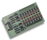
- 16 Opto‑Isolated Digital Input Channels: Each channel is isolated using a 4N35 optocoupler, ensuring electrical separation between field signals and the host system.
- Polarity‑Free AC/DC Input: Accepts both AC and DC signals without concern for polarity, simplifying wiring and integration.
- Adjustable Threshold Voltage: A variable resistor (VR1) allows adjustment of the input threshold level (nominal 1.5 V DC) to accommodate different signal levels and noise environments.
- High Isolation Voltage: 1000 V DC isolation between channels and between channel‑to‑ground, providing robust protection against transient voltages.
- Status Indication: Sixteen on‑board red LEDs display the ON/OFF status of each input channel for easy diagnostics.
- Selectable Input Mode: Each channel can be configured as isolated or non‑isolated (dry contact) via jumper settings (JAn/JBn pairs).
- Fast Response Time: 20 µs typical without AC filter; 2.2 ms with optional AC filter.
- Wide Input Range: Accepts 0–24 V DC or AC (50–1000 Hz) input signals.
- Screw Terminal Interface: Two 18‑position terminal blocks (TB1 and TB2) with 5 mm pitch for secure field wiring (18–22 AWG).
- 20‑Pin Flat Ribbon Connector: Standard interface for connection to ADLINK ACL or PCI digital I/O cards.
- Compact Form Factor: 205 mm × 114 mm × 15 mm PCB suitable for panel or tabletop mounting.
- Compatibility: Fully compatible with ADLINK ACL‑8112, ACL‑8216, ACL‑8316, ACL‑6126, ACL‑7120, and PCI‑9111 series cards.
- Industrial‑Grade Design: Designed for long‑term reliability in automation, control, and monitoring systems.
Comprehensive Product Summary: ADLINK ACLD‑9182A‑01 Isolated 16‑Channel Digital Input Panel
### 1. Product Overview
Product Name: Isolated 16‑Channel Digital Input Panel
Model: ACLD‑9182A‑01
Series: ACLD Series (NuDAQ® Termination Boards)
Article Number: ACLD‑9182A‑01
Manufacturer: ADLINK Technology Inc.
Product Type: Opto‑isolated digital input daughter/termination board for ACL and PCI series data acquisition and digital I/O cards.
Revision Reference: Manual Rev. 2.41, December 21, 2006
Manufacturer Address: ADLINK Technology Inc., 9F, No. 166, Jian Yi Road, Chungho City, Taipei 235, Taiwan
Website: [www.adlinktech.com](http://www.adlinktech.com)
The ADLINK ACLD‑9182A‑01 is a 16‑channel opto‑isolated digital input (DI) panel designed as a termination and signal conditioning board for ADLINK’s NuDAQ and ACL/PCI series data acquisition cards. It provides galvanic isolation between field input signals and the host system, protecting against ground loops, floating potentials, and electrical noise. The board is engineered for industrial and laboratory automation environments requiring reliable digital input interfacing with configurable isolation and threshold control.
### 2. Key Features
- 16 Opto‑Isolated Digital Input Channels: Each channel is isolated using a 4N35 optocoupler, ensuring electrical separation between field signals and the host system.
- Polarity‑Free AC/DC Input: Accepts both AC and DC signals without concern for polarity, simplifying wiring and integration.
- Adjustable Threshold Voltage: A variable resistor (VR1) allows adjustment of the input threshold level (nominal 1.5 V DC) to accommodate different signal levels and noise environments.
- High Isolation Voltage: 1000 V DC isolation between channels and between channel‑to‑ground, providing robust protection against transient voltages.
- Status Indication: Sixteen on‑board red LEDs display the ON/OFF status of each input channel for easy diagnostics.
- Selectable Input Mode: Each channel can be configured as isolated or non‑isolated (dry contact) via jumper settings (JAn/JBn pairs).
- Fast Response Time: 20 µs typical without AC filter; 2.2 ms with optional AC filter.
- Wide Input Range: Accepts 0–24 V DC or AC (50–1000 Hz) input signals.
- Screw Terminal Interface: Two 18‑position terminal blocks (TB1 and TB2) with 5 mm pitch for secure field wiring (18–22 AWG).
- 20‑Pin Flat Ribbon Connector: Standard interface for connection to ADLINK ACL or PCI digital I/O cards.
- Compact Form Factor: 205 mm × 114 mm × 15 mm PCB suitable for panel or tabletop mounting.
- Compatibility: Fully compatible with ADLINK ACL‑8112, ACL‑8216, ACL‑8316, ACL‑6126, ACL‑7120, and PCI‑9111 series cards.
- Industrial‑Grade Design: Designed for long‑term reliability in automation, control, and monitoring systems.
### 3. Technical Specifications
| Parameter | Specification |
|----------------|------------------|
| Number of Input Channels | 16 opto‑isolated digital inputs |
| Optocoupler Type | 4N35 |
| Input Voltage Range | 0 – 24 V DC or AC (50 – 1000 Hz) |
| Threshold Voltage | Adjustable, nominal 1.5 V DC |
| Input Impedance | 1.2 kΩ |
| Input Current | ≤ 50 mA (max for DC input) |
| Isolation Voltage | 1000 V DC (channel‑to‑channel and channel‑to‑ground) |
| Response Time | 20 µs (without AC filter) / 2.2 ms (with AC filter) |
| Input Mode | Isolated or non‑isolated (dry contact) selectable per channel |
| Indication Display | 16 red LEDs (one per channel) |
| Connector Type | 20‑pin flat ribbon cable connector |
| Terminal Blocks | Two 18‑position screw terminals, 5 mm pitch, 18–22 AWG |
| Dimensions (W × D × H) | 205 mm × 114 mm × 15 mm |
| Weight | Approx. 250 g |
| Isolation Device | Opto‑isolator 4N35 |
| Power Supply | +5 V DC and +12 V DC from host or external source |
| Operating Temperature | 0 °C – 50 °C (typical) |
| Storage Temperature | –20 °C – 70 °C |
| Relative Humidity | 0 – 90 % non‑condensing |
| Mounting | Panel or tabletop (nylon standoffs included) |
### 4. Functionality
The ACLD‑9182A‑01 functions as an isolated digital input interface between field devices (switches, sensors, relays) and ADLINK data acquisition or digital I/O cards. Each input channel uses an optocoupler to convert external voltage signals into logic‑level signals recognized by the host card while maintaining galvanic isolation.
Operating Principle:
- When an external voltage (AC or DC) is applied to an input channel, the optocoupler’s LED activates, switching the phototransistor and generating a logic “1” signal.
- When the input voltage is removed or below the threshold, the LED turns off, producing a logic “0.”
- The corresponding on‑board LED indicator lights up when the input is active (logic high).
- The board’s threshold voltage can be fine‑tuned using the VR1 potentiometer to adjust sensitivity for different signal levels or noise conditions.
Use Cases and Applications:
- Industrial ON/OFF signal monitoring
- Machine and process automation
- Alarm and safety interlock systems
- Motor starter and solenoid valve control feedback
- Lighting and HVAC control systems
- Laboratory instrumentation and data logging
- External switch or relay status monitoring
- Ground loop isolation in mixed‑signal environments
Compatibility:
The ACLD‑9182A‑01 connects directly to the digital input ports of ADLINK’s NuDAQ and ACL/PCI series cards via a 20‑pin flat ribbon cable. It is compatible with:
- PCI‑9111 Series
- ACL‑8312 / ACL‑8316
- ACL‑8112 Series
- ACL‑8216
- ACL‑6126
- ACL‑7120
### 5. Components & Accessories
Included Items:
- ACLD‑9182A‑01 Opto‑Isolated Digital Input Board
- 1‑meter 20‑pin flat ribbon cable assembly
- Nylon standoffs for tabletop or panel mounting
- User’s manual and documentation
Connectors and Terminals:
- CN1 (20‑pin flat ribbon connector): Interface to host digital I/O card.
- TB1 and TB2 (screw terminals): Field wiring interface for channels 0–15.
- Power Pins: +5 V (pin 19), +12 V (pin 20), and dual ground pins (17, 18).
Optional Accessories:
- ACL‑10120‑x flat cable (for extended connection lengths)
- External +12 V DC power supply (if host supply is insufficient)
- Replacement current‑limit resistors (RA0–RA15) for higher input voltage ranges
### 6. Installation & Setup
Requirements:
- Compatible ADLINK ACL or PCI digital input card with 20‑pin connector
- +5 V and +12 V DC supply (from host or external source)
- Proper grounding and shielding for industrial environments
Installation Steps:
1. Unpack and Inspect: Verify all components are present and undamaged.
2. Mounting: Use included nylon standoffs for tabletop or panel installation.
3. Connection: Attach the 20‑pin flat ribbon cable between the ACLD‑9182A‑01 and the host card’s digital input connector.
4. Field Wiring: Connect external signal lines to TB1 (channels 0–7) and TB2 (channels 8–15).
5. Jumper Configuration:
- Each channel has two jumpers (JAn, JBn).
- Upper position = Isolated mode; lower position = Non‑isolated (dry contact).
6. Threshold Adjustment:
- Apply a +5 V test signal through a 4 kΩ resistor.
- Adjust VR1 until LED0 just turns off (sets ~1 mA threshold current).
7. Verification: Power on the system and confirm LED indicators correspond to input states.
Mounting Options:
- Tabletop operation using standoffs
- Panel mounting via screw holes on PCB corners
Configuration Notes:
- Channels 0–7 and 8–15 have reversed jumper orientation; refer to board silkscreen for correct placement.
- For higher voltage inputs (> 24 V), replace current‑limit resistors RA0–RA15 using the formula:
*Ri = Vin / IF* (recommended IF ≤ 20 mA).
### 7. Performance & Capabilities
Speed and Response:
- 20 µs typical response without AC filter, suitable for high‑speed digital input applications.
- 2.2 ms response with AC filter enabled for noise‑suppressed operation in AC environments.
Capacity and Efficiency:
- 16 independent channels with full isolation.
- Low power consumption due to efficient optocoupler design.
- Adjustable threshold ensures compatibility with a wide range of sensors and logic levels.
Limitations:
- Maximum input voltage limited to 24 V DC (default configuration).
- For higher voltages, resistor modification is required.
- Not designed for direct connection to high‑voltage mains circuits.
Reliability:
- Industrial‑grade components rated for continuous operation.
- Optocoupler isolation prevents cross‑channel interference and ground loops.
- LED indicators provide immediate visual feedback for troubleshooting.
### 8. Standards & Compliance
- Electrical Isolation: 1000 V DC channel‑to‑channel and channel‑to‑ground per ADLINK specification.
- Safety and EMC: Designed to meet industrial noise immunity and safety standards for data acquisition equipment.
- Compatibility: Fully compliant with ADLINK NuDAQ and ACL/PCI series interface standards.
- RoHS/CE: Manufactured in accordance with ADLINK’s environmental and quality assurance policies (RoHS compliant).
- Trademark Notice: ACLD‑9182A and related product names are registered trademarks of ADLINK Technology Inc.
### 9. Additional Information
Warranty:
- Standard ADLINK limited warranty: two years (one year in China).
- Covers defects in materials and workmanship under normal use.
- Excludes damage from misuse, unauthorized repair, or environmental factors.
- Warranty service requires proof of purchase and RMA authorization.
Support and Service:
- Technical Support: service@adlinktech.com
- Telephone: +886‑2‑82265877
- Fax: +886‑2‑82265717
- Website: [www.adlinktech.com](http://www.adlinktech.com)
- RMA Portal: [rma.adlinktech.com/policy](http://rma.adlinktech.com/policy)
Maintenance:
- Periodically inspect terminal connections for corrosion or looseness.
- Keep the board free from dust and moisture.
- Verify jumper and resistor settings after any reconfiguration.
- Avoid exceeding rated input voltages to maintain optocoupler integrity.
Firmware/Hardware Updates:
- The ACLD‑9182A‑01 is a passive hardware interface; no firmware updates are required.
- Hardware revisions may include improved isolation or updated component tolerances; refer to ADLINK documentation for revision history.
Environmental and Safety Considerations:
- Operate within specified temperature and humidity ranges.
- Ensure proper grounding to prevent electrostatic discharge (ESD) damage.
- Use shielded cables in high‑noise environments to maintain signal integrity.
### Summary
The ADLINK ACLD‑9182A‑01 isolated 16‑channel digital input panel is a robust, industrial‑grade interface board designed to provide safe, reliable, and flexible digital input connectivity for ADLINK’s NuDAQ and ACL/PCI series data acquisition systems. Its opto‑isolated architecture, adjustable threshold, and polarity‑free AC/DC input capability make it ideal for industrial automation, process control, and laboratory monitoring applications. With comprehensive isolation, configurable input modes, and clear LED status indication, the ACLD‑9182A‑01 ensures dependable signal acquisition and protection for sensitive host electronics in demanding environments.
-
ACL-10120-1
- flat cable 20pin 1m
-
ACL-10120-2
- flat cable 20pin 2m
-
ACL-10337
- 2*20 pin to DB 37 slot adapter
-
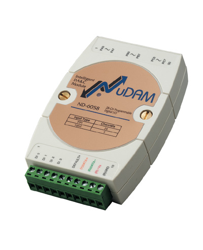
ND-6058
- NuDAM Isolated 5kV Digital 24 Input/Output Module
-
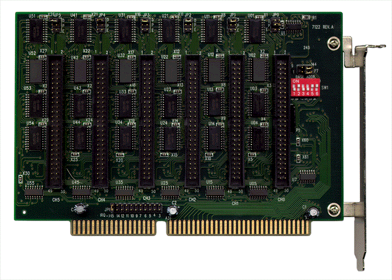
ACL-7122
- 144 DIO Card, 8255 mode 0 compatible
-
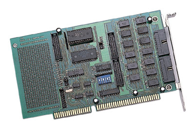
ACL-7124
- 24 DIO Card, 8255 mode 0 compatible
-
PET-48DIO
- 48 DIO Card, 8255 mode 0 compatible
-
PCI-7224
- PCI-Bus Digital IO Card 24DIO Opto-22 Compatible
-
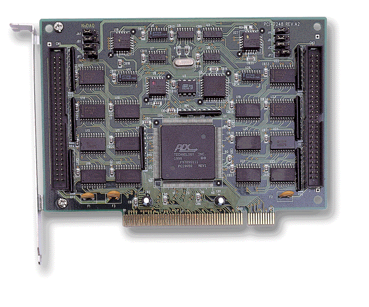
PCI-7248
- PCI-Bus Digital IO Card 48DIO Opto-22 Compatible
-
PCI-7296
- PCI-Bus Digital IO Card, 96DIO, opto-22 compatible



 LOOKING FOR THE RIGHT
 AD9182&85 Manual.PDF
Manual
AD9182&85 Manual.PDF
Manual