- 16 Opto‑Isolated Digital Input Channels: Each channel is electrically isolated using PC‑814 optocouplers, protecting the host system from voltage transients and ground loops.
- AC/DC Input Compatibility: Accepts both AC (50–1000 Hz) and DC (3–24 V) input signals, with polarity‑free operation.
- Adjustable Threshold Level: A variable resistor (VR1) allows fine‑tuning of the input threshold current for all channels, optimizing sensitivity for different signal levels.
- High Isolation Voltage: 1000 V channel‑to‑channel and channel‑to‑ground isolation ensures robust protection in noisy industrial environments.
- Status Indication: Sixteen on‑board red LEDs provide real‑time visual feedback of input logic states.
- Flexible Input Configuration: Each channel can be configured as isolated or non‑isolated (dry contact) via jumper settings (JA0–JA15, JB0–JB15).
- Opto‑Coupler Type: PC‑814 opto‑isolators provide fast response and reliable isolation.
- Response Time: 20 µs (without AC filter) or 2.2 ms (with AC filter), allowing use in both high‑speed and noise‑sensitive applications.
- Connector Interface: 20‑pin flat ribbon connector compatible with ACL and PCI series digital I/O cards.
- Terminal Blocks: Two 18‑position screw terminal blocks (TB1 and TB2) with 5 mm pitch for secure field wiring.
- Compact Form Factor: 205 mm × 114 mm × 15 mm PCB suitable for panel or enclosure mounting.
- Compatibility: Fully compatible with ADLINK ACL and PCI digital I/O boards and functionally similar to Advantech PCLD‑782.
Comprehensive Product Summary – ADLINK ACLD‑9182B Isolated 16‑Channel Digital Input (AC) Panel
### 1. Product Overview
Product Name: Isolated 16‑Channel Digital Input Panel
Model: ACLD‑9182B
Series: ACLD‑91xx Daughter Board Series
Article Number: ACLD‑9182B
Manufacturer: ADLINK Technology Inc.
Product Type: Opto‑isolated digital input daughter board for ACL and PCI series data acquisition and digital I/O cards
Revision Reference: Manual Rev. 2.11, September 15, 1999
The ADLINK ACLD‑9182B is a 16‑channel isolated digital input (DI) panel designed for industrial and laboratory automation systems. It provides opto‑isolated input channels for AC or DC signals, ensuring electrical isolation between field wiring and host systems. The board is part of ADLINK’s ACLD daughter board family, which includes the ACLD‑9185 relay output board and the ACLD‑8125 signal conditioning board.
### 2. Key Features
- 16 Opto‑Isolated Digital Input Channels: Each channel is electrically isolated using PC‑814 optocouplers, protecting the host system from voltage transients and ground loops.
- AC/DC Input Compatibility: Accepts both AC (50–1000 Hz) and DC (3–24 V) input signals, with polarity‑free operation.
- Adjustable Threshold Level: A variable resistor (VR1) allows fine‑tuning of the input threshold current for all channels, optimizing sensitivity for different signal levels.
- High Isolation Voltage: 1000 V channel‑to‑channel and channel‑to‑ground isolation ensures robust protection in noisy industrial environments.
- Status Indication: Sixteen on‑board red LEDs provide real‑time visual feedback of input logic states.
- Flexible Input Configuration: Each channel can be configured as isolated or non‑isolated (dry contact) via jumper settings (JA0–JA15, JB0–JB15).
- Opto‑Coupler Type: PC‑814 opto‑isolators provide fast response and reliable isolation.
- Response Time: 20 µs (without AC filter) or 2.2 ms (with AC filter), allowing use in both high‑speed and noise‑sensitive applications.
- Connector Interface: 20‑pin flat ribbon connector compatible with ACL and PCI series digital I/O cards.
- Terminal Blocks: Two 18‑position screw terminal blocks (TB1 and TB2) with 5 mm pitch for secure field wiring.
- Compact Form Factor: 205 mm × 114 mm × 15 mm PCB suitable for panel or enclosure mounting.
- Compatibility: Fully compatible with ADLINK ACL and PCI digital I/O boards and functionally similar to Advantech PCLD‑782.
### 3. Technical Specifications
| Parameter | Specification |
|----------------|------------------|
| Input Channels | 16 opto‑isolated digital inputs |
| Opto‑Coupler Type | PC‑814 |
| Input Voltage Range | 0 – 24 V DC or AC (50 – 1000 Hz) |
| Input Current | ≤ 50 mA (max for DC input) |
| Logic High Threshold | > 2.0 V |
| Input Impedance | 1.2 kΩ |
| Isolation Voltage | 1000 V channel‑to‑channel and channel‑to‑ground |
| Input Signal Type | AC or DC, polarity‑free |
| Response Time | 20 µs (no filter) / 2.2 ms (with AC filter) |
| Indication Display | 16 red LEDs (one per channel) |
| Connector Type | 20‑pin flat ribbon cable connector |
| Terminal Blocks | Two 18‑position screw terminals, 5 mm spacing, 18–22 AWG wire |
| Dimensions | 205 mm × 114 mm × 15 mm (8.06 in × 4.5 in × 0.6 in) |
| Weight | Approx. 200 g (board only) |
| Operating Frequency Range (AC) | 50 – 1000 Hz |
| Isolation Method | Opto‑isolation using PC‑814 couplers |
| Mounting | Panel or enclosure mounting via standoffs |
| Power Supply | +5 V and +12 V provided through 20‑pin connector |
| Operating Temperature | 0 °C – 50 °C (typical) |
| Storage Temperature | –20 °C – 70 °C |
| Humidity | 0 – 90 % RH, non‑condensing |
### 4. Functionality
The ACLD‑9182B serves as an interface between field‑level digital signals and host data acquisition or control systems. Each input channel uses an opto‑isolator to convert external AC or DC voltage signals into TTL‑compatible logic levels. The opto‑isolation barrier prevents ground loops and voltage surges from affecting the host computer or controller.
Operating Principle:
- When an external voltage is applied to an input channel, current flows through the opto‑coupler LED, activating the phototransistor and generating a logic “1” signal.
- When the input voltage is removed or below threshold, the LED is off, and the output logic is “0.”
- The corresponding LED indicator on the board lights up when the input is active (logic high).
Use Cases and Applications:
- Industrial automation and process control
- Machine status monitoring and alarm systems
- Laboratory instrumentation and data acquisition
- Switch and sensor signal interfacing
- Motor starter and solenoid valve control feedback
- Lighting and building automation systems
Compatibility:
- Works with ADLINK ACL and PCI series digital I/O cards (e.g., ACL‑7120, ACL‑8112, ACL‑8216, PCI‑9112).
- Compatible with Advantech PCLD‑782 wiring modules.
- Connects via standard 20‑pin flat ribbon cable (ACL‑10120‑x series).
### 5. Components & Accessories
Included Items:
- ACLD‑9182B 16‑channel opto‑isolated DI board
- 1‑meter 20‑pin flat ribbon cable assembly
- User manual
Connectors and Terminals:
- CN1: 20‑pin flat ribbon connector for interface to host card
- TB1/TB2: Two screw terminal blocks for field wiring (channels 0–7 and 8–15)
- JA0–JA15 / JB0–JB15: Jumper pairs for isolated/non‑isolated input selection per channel
- VR1: Adjustable resistor for threshold current calibration
Optional Accessories:
- ACL‑10120‑x flat cable (various lengths)
- Panel mounting standoffs or DIN‑rail adapters
- External power supply (if required for extended configurations)
### 6. Installation & Setup
Requirements:
- Compatible ADLINK ACL or PCI digital I/O card with 20‑pin DI connector
- +5 V and +12 V power supplied through the host card or external source
- Proper grounding and shielding for industrial environments
Mounting Options:
- Panel mounting using nylon standoffs
- Integration into control enclosures or test benches
Configuration Steps:
1. Unpack and Inspect: Verify that the board and cable are undamaged.
2. Connect to Host: Attach the 20‑pin ribbon cable between the ACLD‑9182B and the host I/O card.
3. Wire Inputs: Connect field signals to TB1 and TB2 terminals (channels 0–15).
4. Set Input Mode: Configure each channel as isolated or non‑isolated using jumpers JA/JB.
5. Adjust Threshold: Use VR1 to fine‑tune the input current threshold (default ≈ 1 mA).
6. Power Up: Apply system power and verify LED indicators correspond to input states.
Jumper Configuration:
- Isolated Mode: Jumpers installed on upper posts (JA/JB).
- Non‑Isolated Mode: Jumpers installed on lower posts.
- Channels 0–7 and 8–15 have reversed jumper orientation; refer to board silkscreen for correct placement.
Threshold Adjustment Procedure:
- Apply +5 V through a 4 kΩ resistor to DI0.
- Adjust VR1 until LED0 turns off, indicating correct threshold (~1 mA).
- For higher voltage inputs, replace current‑limit resistors (RA0–RA15) using the formula:
- *Ri = Vin / IF*
- *Pw = Vin × IF*
Example: For 40 V input, IF = 20 mA → Ri = 2 kΩ, Pw = 0.8 W (use 1 W resistor).
### 7. Performance & Capabilities
Speed and Response:
- Fast switching capability with 20 µs response time (no filter) for high‑speed digital input capture.
- Optional AC filter increases response time to 2.2 ms, improving noise immunity for AC signals.
Capacity and Efficiency:
- 16 independent channels allow simultaneous monitoring of multiple field devices.
- Low input current consumption ensures minimal load on sensors or switches.
Isolation and Protection:
- 1000 V isolation prevents cross‑channel interference and protects host electronics.
- Opto‑isolators provide long‑term reliability and electrical safety.
Limitations:
- Maximum input voltage limited to 24 V DC (default configuration).
- For higher voltages, current‑limit resistors must be replaced accordingly.
- Not designed for direct connection to high‑voltage mains circuits without external conditioning.
### 8. Standards & Compliance
Certifications and Compliance:
- Designed and manufactured by ADLINK Technology Inc. in accordance with industrial electronic standards.
- Meets CE and FCC Class A requirements for electromagnetic compatibility (typical for ADLINK industrial boards).
- Isolation and safety parameters conform to IEC 61010‑1 for measurement and control equipment.
- RoHS compliance (for later production versions).
Industry Compatibility:
- Fully compatible with ADLINK ACL and PCI series data acquisition systems.
- Functionally equivalent to Advantech PCLD‑782 for cross‑platform integration.
Environmental and Reliability Standards:
- Operating temperature range suitable for industrial environments (0 – 50 °C).
- High insulation resistance (≥ 100 MΩ) ensures long‑term stability.
- Designed for continuous operation in automation and control systems.
### 9. Additional Information
Warranty:
- One‑year limited warranty from date of purchase.
- Covers defects in materials and workmanship under normal use.
- Excludes damage from misuse, modification, or operation beyond specified limits.
- Warranty service requires proof of purchase; return shipping prepaid.
Support and Service:
- Technical support available through ADLINK authorized distributors and service centers.
- Firmware and documentation updates provided via ADLINK’s official website.
- Replacement parts and accessories available for extended product lifecycle support.
Maintenance:
- Periodic inspection of terminal connections and jumpers recommended.
- Keep board free from dust and moisture; store in anti‑static packaging when not in use.
- Avoid exposure to excessive vibration or corrosive environments.
Product Lifecycle and Updates:
- The ACLD‑9182B remains compatible with legacy ACL and PCI series cards.
- Successor models may include enhanced isolation voltage and RoHS‑compliant components.
- Firmware and driver updates are backward‑compatible with existing ADLINK software suites.
### Summary
The ADLINK ACLD‑9182B Isolated 16‑Channel Digital Input Panel is a robust, versatile interface module engineered for industrial and laboratory automation systems requiring reliable signal isolation and monitoring. Its combination of opto‑isolated inputs, adjustable thresholds, and AC/DC compatibility makes it suitable for a wide range of control and monitoring applications. The board’s design emphasizes electrical safety, configurability, and ease of integration with ADLINK’s data acquisition and digital I/O platforms.
With its compact form factor, high isolation voltage, and flexible configuration options, the ACLD‑9182B provides a dependable solution for interfacing field‑level signals to computer‑based control systems, ensuring accurate, noise‑free digital input acquisition in demanding industrial environments.
-
ACL-10120-1
- flat cable 20pin 1m
-
ACL-10120-2
- flat cable 20pin 2m
-
ACL-10337
- 2*20 pin to DB 37 slot adapter
-
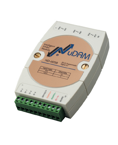
ND-6058
- NuDAM Isolated 5kV Digital 24 Input/Output Module
-
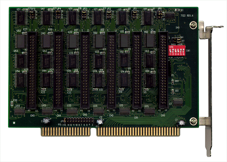
ACL-7122
- 144 DIO Card, 8255 mode 0 compatible
-
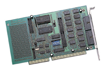
ACL-7124
- 24 DIO Card, 8255 mode 0 compatible
-
PET-48DIO
- 48 DIO Card, 8255 mode 0 compatible
-
PCI-7224
- PCI-Bus Digital IO Card 24DIO Opto-22 Compatible
-
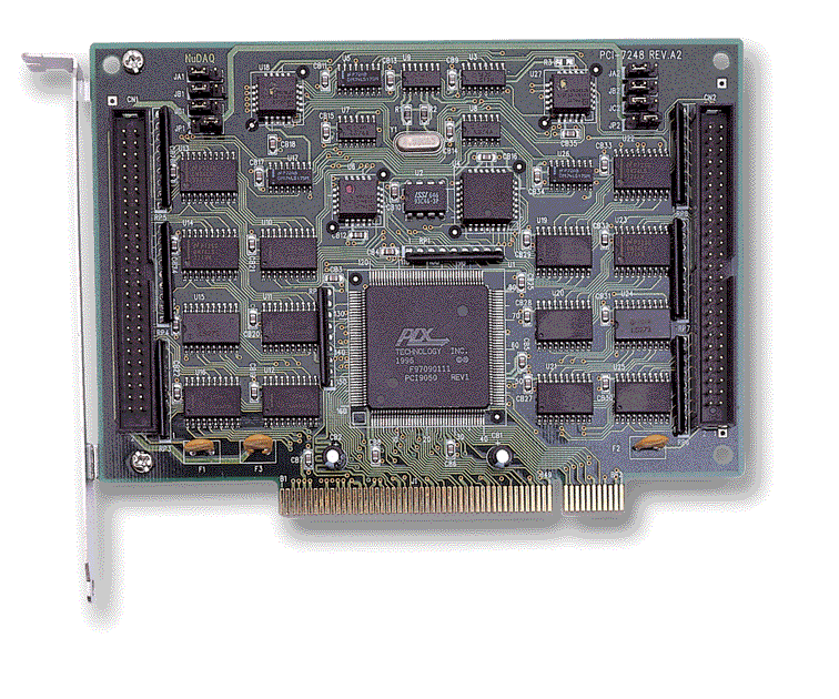
PCI-7248
- PCI-Bus Digital IO Card 48DIO Opto-22 Compatible
-
PCI-7296
- PCI-Bus Digital IO Card, 96DIO, opto-22 compatible


 LOOKING FOR THE RIGHT
 AD9182&85 Manual.PDF
Manual
AD9182&85 Manual.PDF
Manual