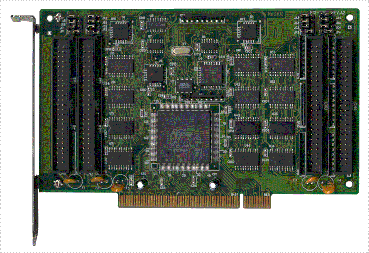
- 16 SPDT (Form C) Relays: Each channel provides a single‑pole, double‑throw contact set (COM, NO, NC) for flexible control of external circuits.
- Isolated Digital Outputs: Provides electrical isolation between control logic and load circuits, protecting host systems from voltage transients.
- LED Status Indicators: Sixteen on‑board LEDs display the ON/OFF state of each relay for quick visual diagnostics.
- On‑Board Relay Drivers: Integrated ULN2003 transistor arrays handle relay coil drive currents directly from TTL/CMOS logic signals.
- High Contact Rating: Each relay supports up to 120 V AC/DC at 1 A continuous load.
- Fast Switching: Typical operate and release times of 3 ms each (10 ms total switching cycle).
- Flexible Power Source: Selectable internal (PC‑bus supplied) or external +12 V DC power via jumper configuration.
- Screw Terminal Interface: Dual 24‑position terminal blocks simplify field wiring and maintenance.
- TTL/CMOS Compatibility: Accepts standard digital output signals from ADLINK ACL or PCI series I/O cards.
- Compact Form Factor: 203 mm × 132 mm PCB with mounting standoffs for tabletop or panel installation.
- Compatibility: Fully compatible with Advantech PCLD‑785 relay board pinout.
- Industrial Reliability: 5 million mechanical operations at full load; 100 MΩ minimum insulation resistance.
- Ease of Integration: Simple programming through host card digital output ports; no additional logic required.
Comprehensive Product Summary – ADLINK ACLD‑9185‑01 Isolated 16‑Channel Relay Output Panel
### 1. Product Overview
Product Name: Isolated 16 DO Relay Panel
Model: ACLD‑9185‑01
Series: ACLD Daughter Board Series (NuDAQ® Termination Boards)
Article Number: ACLD‑9185‑01
Manufacturer: ADLINK Technology Inc.
Product Category: Relay Actuator / Digital Output Daughter Board
Revision Reference: Manual Rev. 2.11 (September 15, 1999); later integrated into NuDAQ Termination Boards Manual Rev. 2.41 (December 21, 2006)
Trademark: ACLD‑9185 is a registered trademark of ADLINK Technology Inc.
The ADLINK ACLD‑9185‑01 is a 16‑channel Single‑Pole‑Double‑Throw (SPDT, Form C) electromechanical relay output board designed as an isolated digital output interface for ADLINK’s ACL and PCI series data acquisition and digital I/O cards. It provides galvanic isolation between control logic and field wiring, enabling safe switching of AC or DC loads up to 120 V / 1 A per channel. The board integrates LED indicators for each relay, screw terminal connections for field wiring, and a 20‑pin flat ribbon connector for host interface.
### 2. Key Features
- 16 SPDT (Form C) Relays: Each channel provides a single‑pole, double‑throw contact set (COM, NO, NC) for flexible control of external circuits.
- Isolated Digital Outputs: Provides electrical isolation between control logic and load circuits, protecting host systems from voltage transients.
- LED Status Indicators: Sixteen on‑board LEDs display the ON/OFF state of each relay for quick visual diagnostics.
- On‑Board Relay Drivers: Integrated ULN2003 transistor arrays handle relay coil drive currents directly from TTL/CMOS logic signals.
- High Contact Rating: Each relay supports up to 120 V AC/DC at 1 A continuous load.
- Fast Switching: Typical operate and release times of 3 ms each (10 ms total switching cycle).
- Flexible Power Source: Selectable internal (PC‑bus supplied) or external +12 V DC power via jumper configuration.
- Screw Terminal Interface: Dual 24‑position terminal blocks simplify field wiring and maintenance.
- TTL/CMOS Compatibility: Accepts standard digital output signals from ADLINK ACL or PCI series I/O cards.
- Compact Form Factor: 203 mm × 132 mm PCB with mounting standoffs for tabletop or panel installation.
- Compatibility: Fully compatible with Advantech PCLD‑785 relay board pinout.
- Industrial Reliability: 5 million mechanical operations at full load; 100 MΩ minimum insulation resistance.
- Ease of Integration: Simple programming through host card digital output ports; no additional logic required.
### 3. Technical Specifications
| Parameter | Specification |
|----------------|------------------|
| Output Channels | 16 isolated relay outputs |
| Relay Type | SPDT (Form C) electromechanical relays |
| Contact Rating | 120 V AC/DC, 1 A |
| Breakdown Voltage | ≥ 1000 V AC/DC |
| Operate Time | ≤ 5 ms (3 ms typical) |
| Release Time | ≤ 5 ms (3 ms typical) |
| Total Switching Time | ~ 10 ms typical |
| Insulation Resistance | ≥ 100 MΩ |
| Mechanical Life Expectancy | 5 million operations at full rated load |
| Power Consumption | +12 V DC @ 33 mA per relay (0.53 A max all ON); +5 V DC < 0.2 A |
| Power Supply Options | Internal (+12 V from PC bus) or External (+12 V DC source) |
| Control Signal Interface | TTL/CMOS compatible digital outputs |
| Connector Type | 20‑pin flat ribbon cable (CN1) |
| Field Wiring Interface | Dual 24‑position screw terminals (2 × 24) |
| Board Dimensions | 203 mm (L) × 132 mm (W) × 15 mm (H) |
| Weight | Approx. 0.3 kg (board only) |
| Operating Voltage Range | +5 V DC logic, +12 V DC relay coil |
| Isolation Voltage | 1000 V channel‑to‑channel and channel‑to‑ground |
| Operating Environment | 0 °C – 50 °C, 0–90 % RH non‑condensing |
| Storage Temperature | –20 °C – 70 °C |
| Mounting | Table‑top or panel mounting via nylon standoffs |
### 4. Functionality
The ACLD‑9185‑01 functions as an isolated relay actuator board for digital output expansion. It receives TTL/CMOS‑level control signals from an ADLINK ACL or PCI series card through a 20‑pin ribbon cable. Each control bit energizes a corresponding relay coil via a ULN2003 driver array. When energized, the relay’s common (COM) contact switches from normally closed (NC) to normally open (NO), allowing control of external AC or DC loads.
Operating Logic:
- Control Bit = High (1): COM → NO contact closed (load energized).
- Control Bit = Low (0): COM → NC contact closed (load de‑energized).
- Default Power‑Up State: All relays de‑energized (logic low).
Typical Use Cases:
- Industrial ON/OFF control of actuators, solenoids, and valves
- External high‑power relay or contactor driving
- Signal routing and switching in automation systems
- Laboratory instrumentation and test setups
- Alarm and lighting control systems
- Motor starter and pump control
- Process control and monitoring applications
Compatibility:
The ACLD‑9185‑01 interfaces directly with ADLINK’s ACL and PCI digital I/O cards, including but not limited to:
PCI‑9111/9112, ACL‑8312/8316, ACL‑8112 Series, ACL‑8216, ACL‑6126, and ACL‑7120.
### 5. Components & Accessories
Included Items:
- ACLD‑9185‑01 Relay Output Board
- 1 m 20‑pin flat ribbon cable assembly (for host connection)
- Nylon standoffs for tabletop or panel mounting
- User’s Manual
Connectors:
- CN1: 20‑pin flat cable connector (signal input from host card)
- CN2/CN3/CN4: Power and field wiring connectors
- Screw Terminals: Two 24‑position terminal blocks for NO/NC/COM wiring per relay
Pin Assignment (CN1):
| Pin | Relay Channel | Contacts | LED No. | Power |
|----------|------------------|---------------|--------------|------------|
| 1 | K0 | COM0 NC0 NO0 | 0 |
-
ACL-10120-1
- flat cable 20pin 1m
-
ACL-10120-2
- flat cable 20pin 2m
-
ACL-10337
- 2*20 pin to DB 37 slot adapter
-
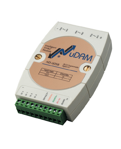
ND-6058
- NuDAM Isolated 5kV Digital 24 Input/Output Module
-
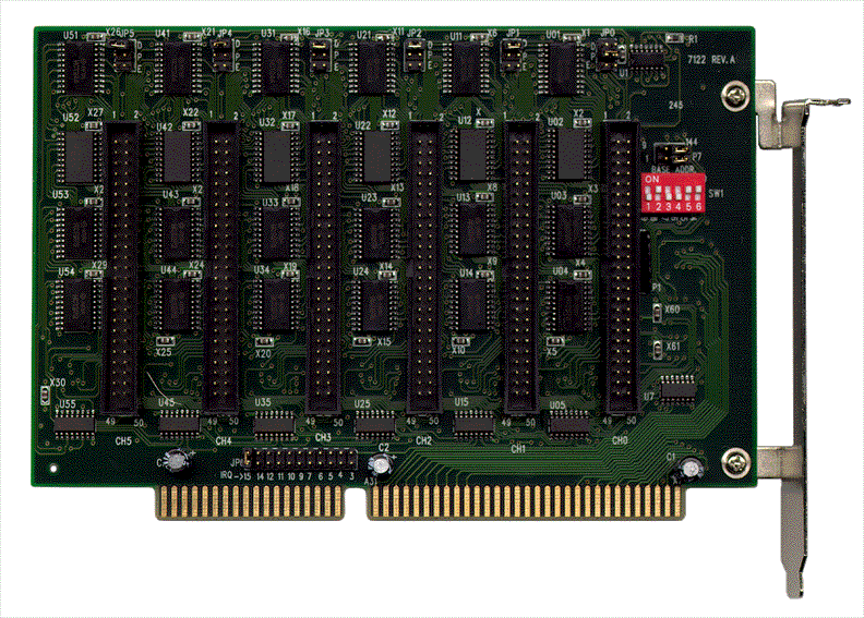
ACL-7122
- 144 DIO Card, 8255 mode 0 compatible
-
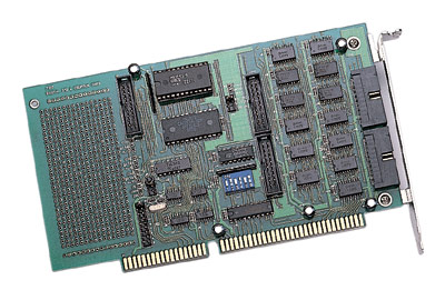
ACL-7124
- 24 DIO Card, 8255 mode 0 compatible
-
PET-48DIO
- 48 DIO Card, 8255 mode 0 compatible
-
PCI-7224
- PCI-Bus Digital IO Card 24DIO Opto-22 Compatible
-
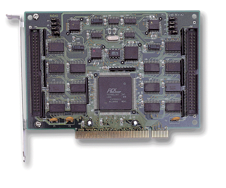
PCI-7248
- PCI-Bus Digital IO Card 48DIO Opto-22 Compatible
-
PCI-7296
- PCI-Bus Digital IO Card, 96DIO, opto-22 compatible



 LOOKING FOR THE RIGHT
 DIN-24R-01+TB-24R-01_Datasheet_en_1.pdf
PDF Catalog
DIN-24R-01+TB-24R-01_Datasheet_en_1.pdf
PDF Catalog
 AD9182&85 Manual.PDF
Manual
AD9182&85 Manual.PDF
Manual