70G-OAC5A
LOOKING FOR THE RIGHT
INDUSTRIAL SOLUTION?
Discover embedded, communication and automation solutions tailored to your application.
- 24‑Position I/O Module Rack:
Accommodates up to 24 Grayhill‑style or Opto‑22‑compatible I/O modules, enabling flexible configuration of input and output combinations.
- DIN Rail Mounting:
Designed for standard DIN rail installation, simplifying integration into industrial control panels and enclosures.
- Isolated I/O Capability:
Each module position provides electrical isolation between field signals and logic circuitry, enhancing system reliability and protecting host equipment from transients and noise.
- Universal Module Support:
Compatible with DC input, DC output, AC input, and AC output modules, allowing mixed‑signal configurations on a single board.
- 50‑Pin Opto‑22‑Compatible Connector:
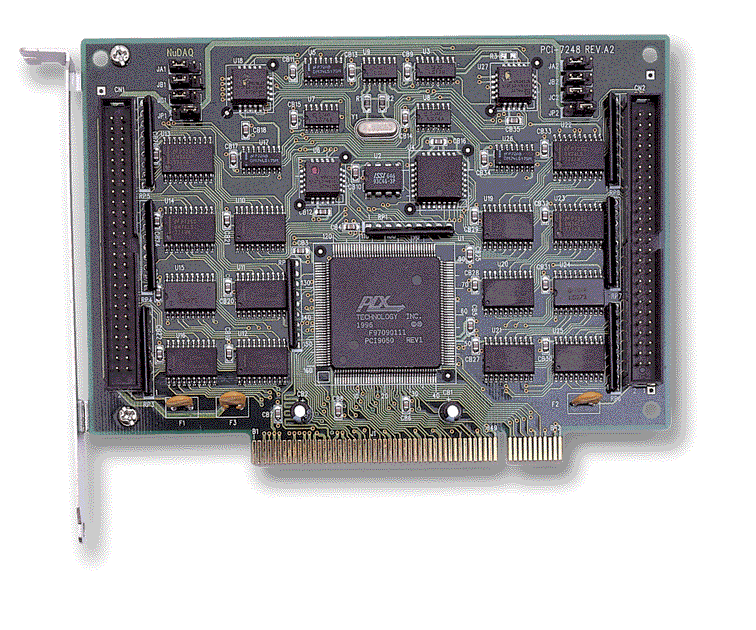
Provides a direct interface to ADLINK DAQ cards (e.g., ACL‑7122, ACL‑7124, PCI‑7248, PCI‑7296) or other Opto‑22‑standard devices.
- Logic Power Supply Interface:
Dedicated logic supply terminals provide regulated power for module operation.
- Field Terminal Blocks:
Integrated terminal blocks simplify field wiring and signal distribution to external devices.
- High Isolation Voltage:
Designed to maintain robust isolation between logic and field sides, ensuring safe operation in electrically noisy environments.
- Modular Expansion:
Enables scalable I/O expansion for industrial automation, process control, and data acquisition systems.
Accommodates up to 24 Grayhill‑style or Opto‑22‑compatible I/O modules, enabling flexible configuration of input and output combinations.
- DIN Rail Mounting:
Designed for standard DIN rail installation, simplifying integration into industrial control panels and enclosures.
- Isolated I/O Capability:
Each module position provides electrical isolation between field signals and logic circuitry, enhancing system reliability and protecting host equipment from transients and noise.
- Universal Module Support:
Compatible with DC input, DC output, AC input, and AC output modules, allowing mixed‑signal configurations on a single board.
- 50‑Pin Opto‑22‑Compatible Connector:
Provides a direct interface to ADLINK DAQ cards (e.g., ACL‑7122, ACL‑7124, PCI‑7248, PCI‑7296) or other Opto‑22‑standard devices.
- Logic Power Supply Interface:
Dedicated logic supply terminals provide regulated power for module operation.
- Field Terminal Blocks:
Integrated terminal blocks simplify field wiring and signal distribution to external devices.
- High Isolation Voltage:
Designed to maintain robust isolation between logic and field sides, ensuring safe operation in electrically noisy environments.
- Modular Expansion:
Enables scalable I/O expansion for industrial automation, process control, and data acquisition systems.
Comprehensive Product Summary: ADLINK DIN‑24G Isolated 24‑Module DIN Rail Board
### 1. Product Overview
Product Name: DIN‑24G
Model: DIN‑24G
Series: DIN‑24 Series Terminal Boards
Article Number: DIN‑24G
Manufacturer: ADLINK Technology Inc.
Product Type: Isolated 24‑module I/O termination board for DIN rail mounting
Product Category: Industrial I/O interface and termination hardware
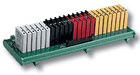
The ADLINK DIN‑24G is a modular DIN‑rail‑mounted terminal board designed to host up to twenty‑four Grayhill‑type I/O modules. It provides a flexible, isolated interface between field wiring and data acquisition (DAQ) or digital I/O (DIO) systems. The board supports a wide range of I/O module types—including DC input, DC output, AC input, and AC output modules—and connects directly to ADLINK’s NuDAQ and NuDAM series or other Opto‑22‑compatible DAQ hardware via a 50‑pin ribbon connector.
### 2. Key Features
- 24‑Position I/O Module Rack:
Accommodates up to 24 Grayhill‑style or Opto‑22‑compatible I/O modules, enabling flexible configuration of input and output combinations.
- DIN Rail Mounting:
Designed for standard DIN rail installation, simplifying integration into industrial control panels and enclosures.
- Isolated I/O Capability:
Each module position provides electrical isolation between field signals and logic circuitry, enhancing system reliability and protecting host equipment from transients and noise.
- Universal Module Support:
Compatible with DC input, DC output, AC input, and AC output modules, allowing mixed‑signal configurations on a single board.
- 50‑Pin Opto‑22‑Compatible Connector:
Provides a direct interface to ADLINK DAQ cards (e.g., ACL‑7122, ACL‑7124, PCI‑7248, PCI‑7296) or other Opto‑22‑standard devices.
- Logic Power Supply Interface:
Dedicated logic supply terminals provide regulated power for module operation.
- Field Terminal Blocks:
Integrated terminal blocks simplify field wiring and signal distribution to external devices.
- High Isolation Voltage:
Designed to maintain robust isolation between logic and field sides, ensuring safe operation in electrically noisy environments.
- Modular Expansion:
Enables scalable I/O expansion for industrial automation, process control, and data acquisition systems.
### 3. Technical Specifications
| Parameter | Specification |
|----------------|-------------------|
| Module Capacity | 24 module positions for Grayhill or Opto‑22‑compatible I/O modules |
| Supported Module Types | DC input, DC output, AC input, AC output |
| Connector Type | 50‑pin Opto‑22‑compatible straight header |
| Terminal Blocks | Field terminal blocks for external wiring |
| Logic Supply | Dedicated logic power input for module operation |
| Isolation Voltage | Module‑dependent; typically up to 2500–5000 V DC isolation per channel |
| Mounting Type | DIN rail (standard 35 mm rail) |
| Material | Industrial‑grade PCB with reinforced insulation and terminal hardware |
| Operating Voltage (Logic) | +5 V DC nominal (supplied via logic connector) |
| I/O Interface Standard | Opto‑22 compatible pinout |
| Number of Connectors | 6 total (including logic supply, terminal blocks, and 50‑pin header) |
| LED Indicators | Module‑dependent (status indication provided by installed modules) |
| Dimensions | Form factor consistent with 24‑position DIN rail boards (approx. 300 mm length typical) |
| Weight | Approx. 0.5–0.8 kg (depending on module population) |
| Operating Temperature | 0 °C to +60 °C typical |
| Storage Temperature | −20 °C to +85 °C |
| Humidity | 5 %–95 % non‑condensing |
### 4. Functionality
The DIN‑24G serves as a modular interface platform between field devices and host DAQ or control systems. Each of the 24 module positions can accept a plug‑in I/O module that performs signal conditioning, isolation, and switching functions. Modules can be mixed and matched to create custom configurations—such as all‑input, all‑output, or hybrid I/O arrays.
Operational Concept:
1. Signal Input/Output:
Field signals are wired to the terminal blocks corresponding to each module position. Depending on the installed module type, these terminals handle AC or DC voltage and current levels.
2. Module Interface:
Each module provides galvanic isolation and signal conversion between the field side and the logic side. For example, a DC input module converts a 24 V DC field signal into a TTL‑compatible logic level.
3. Logic Connection:
The 50‑pin header connects to a DAQ or DIO card using a flat ribbon cable. The pinout follows the Opto‑22 standard, mapping 24 channels across ports A, B, and C, plus a +5 V logic supply line.
4. Power Distribution:
The logic supply connector provides regulated +5 V DC to power the logic side of the modules. Field power for AC/DC loads is supplied externally through the terminal blocks.
Typical Use Cases:
- Industrial automation and process control systems
- Machine I/O expansion for PLCs or PC‑based controllers
- Data acquisition and monitoring applications
- Laboratory test setups requiring isolated signal interfacing
- Signal conditioning for sensors, actuators, and relays
Compatibility:
- ADLINK NuDAQ and NuDAM series DAQ modules
- Opto‑22‑compatible digital I/O boards (ACL‑7122, ACL‑7124, PCI‑7248, PCI‑7296, PET‑48DIO, etc.)
- 50‑pin SCSI‑type digital I/O interfaces (e.g., ND‑6058)
### 5. Components & Accessories
Included Components:
- DIN‑24G terminal board assembly
- Integrated 24‑position I/O module rack
- Logic supply connector
- Field terminal blocks for external wiring
- 50‑pin Opto‑22‑compatible header connector
Optional Accessories:
- Grayhill or Opto‑22‑style I/O modules (DC input/output, AC input/output)
- 50‑pin ribbon cable for connection to DAQ or DIO boards
- DIN rail mounting clips and hardware
- External power supply for logic and field circuits
- Protective cover or enclosure for industrial environments
Connectors Overview:
- Logic Supply Connector: Provides +5 V DC logic power.
- Terminal Block Connectors: Interface for field wiring to external devices.
- 50‑Pin Header Connector: Standard Opto‑22 pinout for connection to host DAQ hardware.
### 6. Installation & Setup
Mounting Requirements:
- Standard 35 mm DIN rail (EN 50022)
- Adequate panel space for 24‑module width (approx. 300 mm)
- Proper grounding and shielding for noise immunity
Installation Steps:
1. Mounting:
Snap the DIN‑24G onto the DIN rail using the integrated mounting clips. Ensure firm mechanical engagement.
2. Module Installation:
Insert up to 24 I/O modules into the designated slots. Verify correct orientation and seating.
3. Logic Power Connection:
Connect the +5 V DC logic supply to the logic power terminals. Observe polarity and voltage limits.
4. Field Wiring:
Connect external devices (sensors, actuators, relays) to the terminal blocks corresponding to each module position. Follow the wiring diagram for the specific module type.
5. DAQ Interface Connection:
Attach a 50‑pin ribbon cable between the DIN‑24G header and the DAQ or DIO card. Ensure pin alignment with the Opto‑22 standard.
6. Verification:
Power on the system and verify module operation using LED indicators (if present) or host software diagnostics.
Configuration Notes:
- Modules can be mixed (e.g., 12 × DC input + 12 × relay output).
- Ensure that the logic supply and field supply voltages match the module specifications.
- Observe isolation ratings and avoid exceeding maximum voltage or current limits.
### 7. Performance & Capabilities
Electrical Performance:
- Logic Interface: TTL‑compatible via Opto‑22 pinout
- Signal Isolation: Up to 2500–5000 V DC (module‑dependent)
- Switching Capacity: Determined by installed module type (e.g., relay modules rated up to 2 A @ 250 V AC)
- Input Voltage Range: Typically 3 V DC to 24 V DC for DC input modules
- Response Time: Module‑dependent (typically < 10 ms for relay outputs, < 1 ms for solid‑state inputs)
Mechanical Performance:
- Durability: Industrial‑grade PCB and connectors rated for extended service life
- Vibration Resistance: Suitable for standard industrial environments when properly mounted
- Thermal Stability: Operates reliably within 0 °C – 60 °C ambient range
System Capacity:
- Supports up to 24 independent I/O channels
- Expandable by cascading multiple DIN‑24G boards via additional DAQ channels
Limitations:
- Requires external logic and field power supplies
- Module performance limited by individual module specifications
- Not intended for direct connection to high‑voltage mains without appropriate isolation modules
### 8. Standards & Compliance
Electrical and Mechanical Standards:
- Opto‑22 I/O module interface standard
- DIN rail mounting standard (EN 50022)
- TTL/CMOS logic compatibility for DAQ interfacing
Safety and Regulatory Compliance:
- Designed in accordance with industrial safety and EMC practices
- Isolation and surge withstand ratings conform to FCC and UL/CSA component standards (as applicable to installed modules)
- Manufactured under ADLINK’s ISO‑certified quality management system
Environmental Compliance:
- RoHS‑compliant materials (lead‑free solder and components)
- Designed for industrial temperature and humidity ranges
### 9. Additional Information
Warranty:
- Duration: 1‑year limited warranty from date of purchase
- Coverage: Defects in materials and workmanship under normal use
- Exclusions: Damage due to misuse, modification, or operation beyond specified limits; removal of serial number; repairs performed outside authorized service centers
- Remedy: Repair or replacement at ADLINK’s discretion upon return of defective unit (postage prepaid)
Support & Service:
- Manufacturer: ADLINK Technology Inc.
- Address: 9F, No. 166, Jian Yi Road, Chungho City, Taipei 235, Taiwan, R.O.C.
- Telephone: +886‑2‑8226‑5877
- Fax: +886‑2‑8226‑5717
- Website: [www.adlink.com.tw](http://www.adlink.com.tw)
- Email Contacts:
- General Service: service@adlink.com.tw
- Technical Support (NuDAQ): nudaq@adlink.com.tw
- Support (NuDAM): nudam@adlink.com.tw
- Software: sw@adlink.com.tw
- Industrial PCs: nuipc@adlink.com.tw
- Embedded Boards: nupro@adlink.com.tw
Maintenance:
- Periodically inspect terminal connections for tightness and corrosion.
- Ensure modules are securely seated and free from dust or debris.
- Verify logic supply voltage stability and grounding integrity.
- Replace defective modules with identical or equivalent types.
Firmware/Hardware Updates:
- The DIN‑24G is a passive hardware interface; no firmware updates are required.
- Hardware revisions may be released to improve reliability or compatibility; refer to ADLINK documentation for revision history.
Service Procedure:
- Contact ADLINK technical support with product model, serial number, and problem description.
- Obtain a Return Material Authorization (RMA) before shipping.
- Package securely and insure the shipment.
### Summary
The ADLINK DIN‑24G is a robust, modular, and highly flexible DIN‑rail‑mounted terminal board designed for industrial I/O expansion. By supporting up to 24 isolated Grayhill‑style I/O modules, it enables engineers to build customized input/output configurations for data acquisition, automation, and control systems. Its Opto‑22‑compatible 50‑pin interface ensures seamless integration with ADLINK’s NuDAQ and NuDAM product lines, while the DIN rail form factor simplifies installation in control cabinets.
With its combination of electrical isolation, modular scalability, and industrial durability, the DIN‑24G provides a reliable foundation for interfacing field signals to PC‑based or embedded control systems in manufacturing, process automation, and laboratory environments.

### 1. Product Overview
Product Name: DIN‑24G
Model: DIN‑24G
Series: DIN‑24 Series Terminal Boards
Article Number: DIN‑24G
Manufacturer: ADLINK Technology Inc.
Product Type: Isolated 24‑module I/O termination board for DIN rail mounting
Product Category: Industrial I/O interface and termination hardware
The ADLINK DIN‑24G is a modular DIN‑rail‑mounted terminal board designed to host up to twenty‑four Grayhill‑type I/O modules. It provides a flexible, isolated interface between field wiring and data acquisition (DAQ) or digital I/O (DIO) systems. The board supports a wide range of I/O module types—including DC input, DC output, AC input, and AC output modules—and connects directly to ADLINK’s NuDAQ and NuDAM series or other Opto‑22‑compatible DAQ hardware via a 50‑pin ribbon connector.
### 2. Key Features
- 24‑Position I/O Module Rack:
Accommodates up to 24 Grayhill‑style or Opto‑22‑compatible I/O modules, enabling flexible configuration of input and output combinations.
- DIN Rail Mounting:
Designed for standard DIN rail installation, simplifying integration into industrial control panels and enclosures.
- Isolated I/O Capability:
Each module position provides electrical isolation between field signals and logic circuitry, enhancing system reliability and protecting host equipment from transients and noise.
- Universal Module Support:
Compatible with DC input, DC output, AC input, and AC output modules, allowing mixed‑signal configurations on a single board.
- 50‑Pin Opto‑22‑Compatible Connector:
Provides a direct interface to ADLINK DAQ cards (e.g., ACL‑7122, ACL‑7124, PCI‑7248, PCI‑7296) or other Opto‑22‑standard devices.
- Logic Power Supply Interface:
Dedicated logic supply terminals provide regulated power for module operation.
- Field Terminal Blocks:
Integrated terminal blocks simplify field wiring and signal distribution to external devices.
- High Isolation Voltage:
Designed to maintain robust isolation between logic and field sides, ensuring safe operation in electrically noisy environments.
- Modular Expansion:
Enables scalable I/O expansion for industrial automation, process control, and data acquisition systems.
### 3. Technical Specifications
| Parameter | Specification |
|----------------|-------------------|
| Module Capacity | 24 module positions for Grayhill or Opto‑22‑compatible I/O modules |
| Supported Module Types | DC input, DC output, AC input, AC output |
| Connector Type | 50‑pin Opto‑22‑compatible straight header |
| Terminal Blocks | Field terminal blocks for external wiring |
| Logic Supply | Dedicated logic power input for module operation |
| Isolation Voltage | Module‑dependent; typically up to 2500–5000 V DC isolation per channel |
| Mounting Type | DIN rail (standard 35 mm rail) |
| Material | Industrial‑grade PCB with reinforced insulation and terminal hardware |
| Operating Voltage (Logic) | +5 V DC nominal (supplied via logic connector) |
| I/O Interface Standard | Opto‑22 compatible pinout |
| Number of Connectors | 6 total (including logic supply, terminal blocks, and 50‑pin header) |
| LED Indicators | Module‑dependent (status indication provided by installed modules) |
| Dimensions | Form factor consistent with 24‑position DIN rail boards (approx. 300 mm length typical) |
| Weight | Approx. 0.5–0.8 kg (depending on module population) |
| Operating Temperature | 0 °C to +60 °C typical |
| Storage Temperature | −20 °C to +85 °C |
| Humidity | 5 %–95 % non‑condensing |
### 4. Functionality
The DIN‑24G serves as a modular interface platform between field devices and host DAQ or control systems. Each of the 24 module positions can accept a plug‑in I/O module that performs signal conditioning, isolation, and switching functions. Modules can be mixed and matched to create custom configurations—such as all‑input, all‑output, or hybrid I/O arrays.
Operational Concept:
1. Signal Input/Output:
Field signals are wired to the terminal blocks corresponding to each module position. Depending on the installed module type, these terminals handle AC or DC voltage and current levels.
2. Module Interface:
Each module provides galvanic isolation and signal conversion between the field side and the logic side. For example, a DC input module converts a 24 V DC field signal into a TTL‑compatible logic level.
3. Logic Connection:
The 50‑pin header connects to a DAQ or DIO card using a flat ribbon cable. The pinout follows the Opto‑22 standard, mapping 24 channels across ports A, B, and C, plus a +5 V logic supply line.
4. Power Distribution:
The logic supply connector provides regulated +5 V DC to power the logic side of the modules. Field power for AC/DC loads is supplied externally through the terminal blocks.
Typical Use Cases:
- Industrial automation and process control systems
- Machine I/O expansion for PLCs or PC‑based controllers
- Data acquisition and monitoring applications
- Laboratory test setups requiring isolated signal interfacing
- Signal conditioning for sensors, actuators, and relays
Compatibility:
- ADLINK NuDAQ and NuDAM series DAQ modules
- Opto‑22‑compatible digital I/O boards (ACL‑7122, ACL‑7124, PCI‑7248, PCI‑7296, PET‑48DIO, etc.)
- 50‑pin SCSI‑type digital I/O interfaces (e.g., ND‑6058)
### 5. Components & Accessories
Included Components:
- DIN‑24G terminal board assembly
- Integrated 24‑position I/O module rack
- Logic supply connector
- Field terminal blocks for external wiring
- 50‑pin Opto‑22‑compatible header connector
Optional Accessories:
- Grayhill or Opto‑22‑style I/O modules (DC input/output, AC input/output)
- 50‑pin ribbon cable for connection to DAQ or DIO boards
- DIN rail mounting clips and hardware
- External power supply for logic and field circuits
- Protective cover or enclosure for industrial environments
Connectors Overview:
- Logic Supply Connector: Provides +5 V DC logic power.
- Terminal Block Connectors: Interface for field wiring to external devices.
- 50‑Pin Header Connector: Standard Opto‑22 pinout for connection to host DAQ hardware.
### 6. Installation & Setup
Mounting Requirements:
- Standard 35 mm DIN rail (EN 50022)
- Adequate panel space for 24‑module width (approx. 300 mm)
- Proper grounding and shielding for noise immunity
Installation Steps:
1. Mounting:
Snap the DIN‑24G onto the DIN rail using the integrated mounting clips. Ensure firm mechanical engagement.
2. Module Installation:
Insert up to 24 I/O modules into the designated slots. Verify correct orientation and seating.
3. Logic Power Connection:
Connect the +5 V DC logic supply to the logic power terminals. Observe polarity and voltage limits.
4. Field Wiring:
Connect external devices (sensors, actuators, relays) to the terminal blocks corresponding to each module position. Follow the wiring diagram for the specific module type.
5. DAQ Interface Connection:
Attach a 50‑pin ribbon cable between the DIN‑24G header and the DAQ or DIO card. Ensure pin alignment with the Opto‑22 standard.
6. Verification:
Power on the system and verify module operation using LED indicators (if present) or host software diagnostics.
Configuration Notes:
- Modules can be mixed (e.g., 12 × DC input + 12 × relay output).
- Ensure that the logic supply and field supply voltages match the module specifications.
- Observe isolation ratings and avoid exceeding maximum voltage or current limits.
### 7. Performance & Capabilities
Electrical Performance:
- Logic Interface: TTL‑compatible via Opto‑22 pinout
- Signal Isolation: Up to 2500–5000 V DC (module‑dependent)
- Switching Capacity: Determined by installed module type (e.g., relay modules rated up to 2 A @ 250 V AC)
- Input Voltage Range: Typically 3 V DC to 24 V DC for DC input modules
- Response Time: Module‑dependent (typically < 10 ms for relay outputs, < 1 ms for solid‑state inputs)
Mechanical Performance:
- Durability: Industrial‑grade PCB and connectors rated for extended service life
- Vibration Resistance: Suitable for standard industrial environments when properly mounted
- Thermal Stability: Operates reliably within 0 °C – 60 °C ambient range
System Capacity:
- Supports up to 24 independent I/O channels
- Expandable by cascading multiple DIN‑24G boards via additional DAQ channels
Limitations:
- Requires external logic and field power supplies
- Module performance limited by individual module specifications
- Not intended for direct connection to high‑voltage mains without appropriate isolation modules
### 8. Standards & Compliance
Electrical and Mechanical Standards:
- Opto‑22 I/O module interface standard
- DIN rail mounting standard (EN 50022)
- TTL/CMOS logic compatibility for DAQ interfacing
Safety and Regulatory Compliance:
- Designed in accordance with industrial safety and EMC practices
- Isolation and surge withstand ratings conform to FCC and UL/CSA component standards (as applicable to installed modules)
- Manufactured under ADLINK’s ISO‑certified quality management system
Environmental Compliance:
- RoHS‑compliant materials (lead‑free solder and components)
- Designed for industrial temperature and humidity ranges
### 9. Additional Information
Warranty:
- Duration: 1‑year limited warranty from date of purchase
- Coverage: Defects in materials and workmanship under normal use
- Exclusions: Damage due to misuse, modification, or operation beyond specified limits; removal of serial number; repairs performed outside authorized service centers
- Remedy: Repair or replacement at ADLINK’s discretion upon return of defective unit (postage prepaid)
Support & Service:
- Manufacturer: ADLINK Technology Inc.
- Address: 9F, No. 166, Jian Yi Road, Chungho City, Taipei 235, Taiwan, R.O.C.
- Telephone: +886‑2‑8226‑5877
- Fax: +886‑2‑8226‑5717
- Website: [www.adlink.com.tw](http://www.adlink.com.tw)
- Email Contacts:
- General Service: service@adlink.com.tw
- Technical Support (NuDAQ): nudaq@adlink.com.tw
- Support (NuDAM): nudam@adlink.com.tw
- Software: sw@adlink.com.tw
- Industrial PCs: nuipc@adlink.com.tw
- Embedded Boards: nupro@adlink.com.tw
Maintenance:
- Periodically inspect terminal connections for tightness and corrosion.
- Ensure modules are securely seated and free from dust or debris.
- Verify logic supply voltage stability and grounding integrity.
- Replace defective modules with identical or equivalent types.
Firmware/Hardware Updates:
- The DIN‑24G is a passive hardware interface; no firmware updates are required.
- Hardware revisions may be released to improve reliability or compatibility; refer to ADLINK documentation for revision history.
Service Procedure:
- Contact ADLINK technical support with product model, serial number, and problem description.
- Obtain a Return Material Authorization (RMA) before shipping.
- Package securely and insure the shipment.
### Summary
The ADLINK DIN‑24G is a robust, modular, and highly flexible DIN‑rail‑mounted terminal board designed for industrial I/O expansion. By supporting up to 24 isolated Grayhill‑style I/O modules, it enables engineers to build customized input/output configurations for data acquisition, automation, and control systems. Its Opto‑22‑compatible 50‑pin interface ensures seamless integration with ADLINK’s NuDAQ and NuDAM product lines, while the DIN rail form factor simplifies installation in control cabinets.
With its combination of electrical isolation, modular scalability, and industrial durability, the DIN‑24G provides a reliable foundation for interfacing field signals to PC‑based or embedded control systems in manufacturing, process automation, and laboratory environments.

-
TB-DIN24X Manual.PDF
Manual
- 70G-OAC5A - G5 digital 240V AC output module
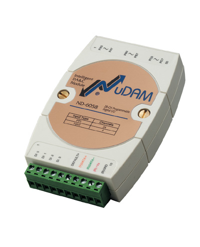
- ND-6058 - NuDAM Isolated 5kV Digital 24 Input/Output Module
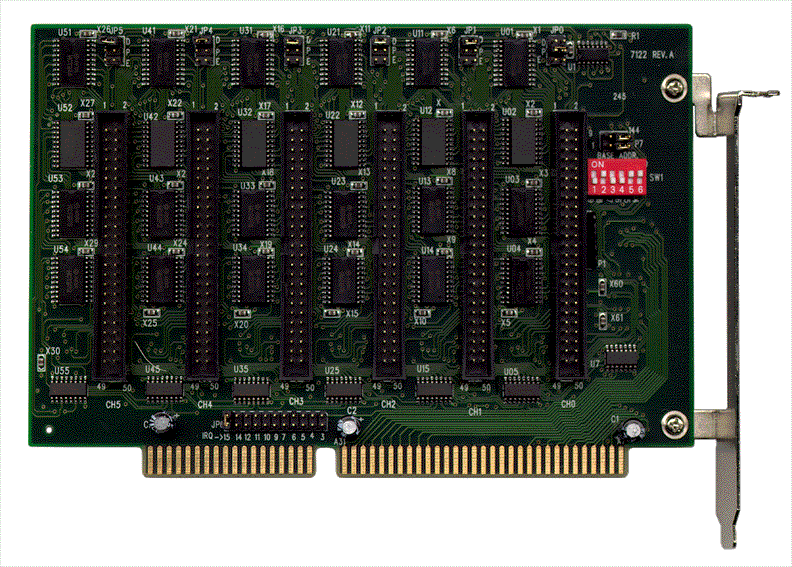
- ACL-7122 - 144 DIO Card, 8255 mode 0 compatible
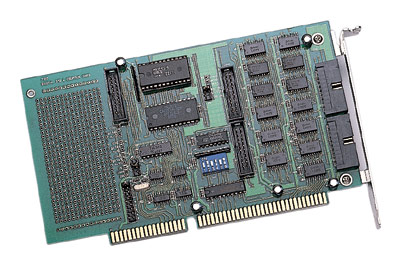
- ACL-7124 - 24 DIO Card, 8255 mode 0 compatible
- PET-48DIO - 48 DIO Card, 8255 mode 0 compatible
- PCI-7224 - PCI-Bus Digital IO Card 24DIO Opto-22 Compatible
- PCI-7248 - PCI-Bus Digital IO Card 48DIO Opto-22 Compatible
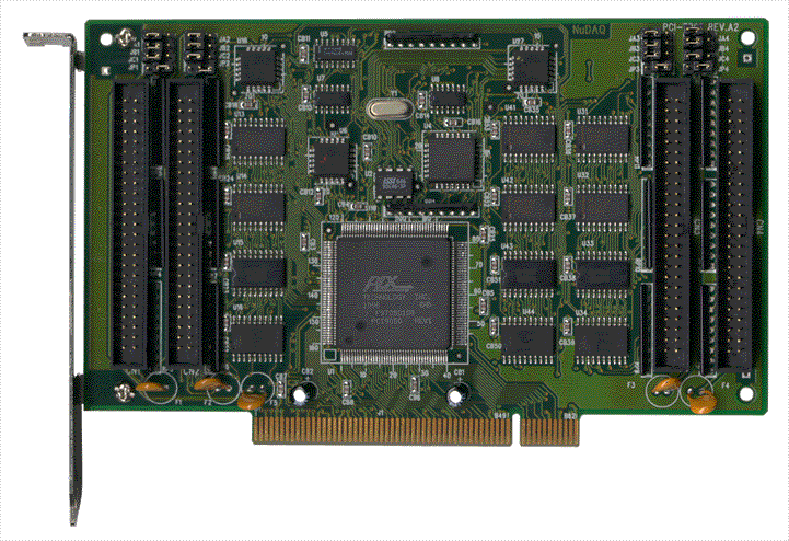
- PCI-7296 - PCI-Bus Digital IO Card, 96DIO, opto-22 compatible