WD-DASK
LOOKING FOR THE RIGHT
INDUSTRIAL SOLUTION?
Discover embedded, communication and automation solutions tailored to your application.
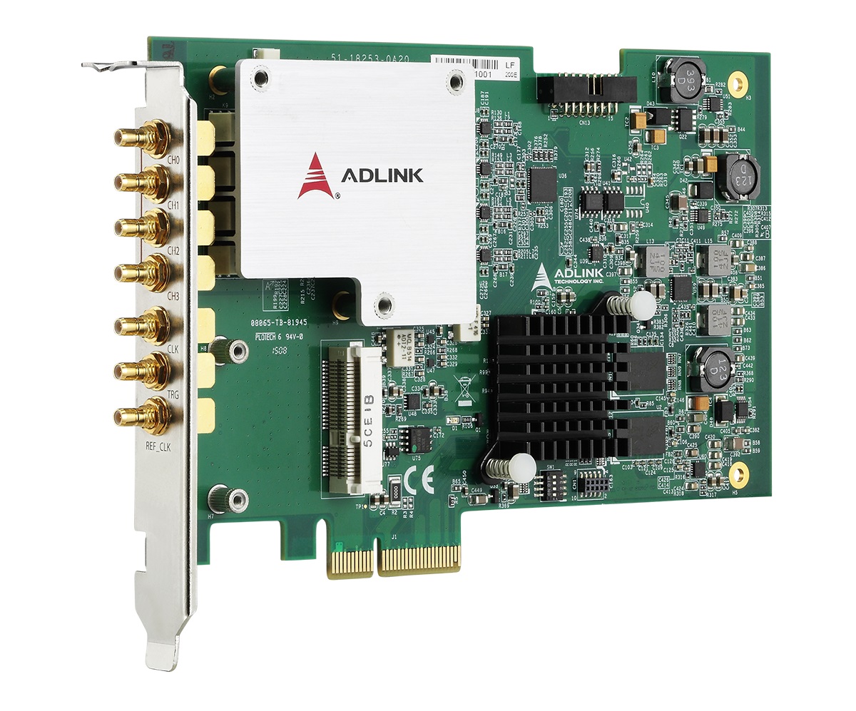
PCIe-9834
PCIe*4 AD Board 80MS/s 16bit 4*Chan 1GB Onboard Memory
including VAT 3,451.00 EUR
- High‑Speed Sampling: Up to 80 MS/s per channel with simultaneous acquisition across four channels.
- High Resolution: 16‑bit analog‑to‑digital conversion for superior signal fidelity.
- Wide Bandwidth: 40 MHz analog input bandwidth supporting high‑frequency signal capture.
- Programmable Input Range: ±0.5 V, ±1 V, ±5 V, or ±10 V ranges; ±10 V supported only at 1 MΩ input impedance.
- Selectable Input Impedance: 50 Ω or 1 MΩ, software‑selectable per channel.
- Large Onboard Memory: 1 GB shared acquisition memory for extended recording at full sampling rate.
- FPGA‑Based Digital Filtering: Selectable 10 MHz or 20 MHz digital low‑pass filter.
- Scatter‑Gather DMA: High‑speed, low‑latency data transfer to host memory without CPU overhead.
- Trigger Flexibility: Supports software, analog, external digital, and SSI (System Synchronization Interface) triggers.
- Auto‑Calibration: Fully automated offset and gain calibration using onboard precision reference voltages.
- Synchronization Support: SSI interface for multi‑card synchronization; optional PLL module (PCIe‑9834P) for precise clock alignment.
- Software Ecosystem: Drivers and SDKs for Windows and Linux; compatible with LabVIEW, MATLAB, and Visual Studio.
- Environmental Compliance: RoHS and WEEE compliant; CE and FCC Class A certified.
- High Resolution: 16‑bit analog‑to‑digital conversion for superior signal fidelity.
- Wide Bandwidth: 40 MHz analog input bandwidth supporting high‑frequency signal capture.
- Programmable Input Range: ±0.5 V, ±1 V, ±5 V, or ±10 V ranges; ±10 V supported only at 1 MΩ input impedance.
- Selectable Input Impedance: 50 Ω or 1 MΩ, software‑selectable per channel.
- Large Onboard Memory: 1 GB shared acquisition memory for extended recording at full sampling rate.
- FPGA‑Based Digital Filtering: Selectable 10 MHz or 20 MHz digital low‑pass filter.
- Scatter‑Gather DMA: High‑speed, low‑latency data transfer to host memory without CPU overhead.
- Trigger Flexibility: Supports software, analog, external digital, and SSI (System Synchronization Interface) triggers.
- Auto‑Calibration: Fully automated offset and gain calibration using onboard precision reference voltages.
- Synchronization Support: SSI interface for multi‑card synchronization; optional PLL module (PCIe‑9834P) for precise clock alignment.
- Software Ecosystem: Drivers and SDKs for Windows and Linux; compatible with LabVIEW, MATLAB, and Visual Studio.
- Environmental Compliance: RoHS and WEEE compliant; CE and FCC Class A certified.
Comprehensive Product Summary: ADLINK PCIe-9834 4-Channel 16-Bit 80 MS/s PCI Express Digitizer
### 1. Product Overview
- Product Name: PCIe-9834
- Model: PCIe-9834 / PCIe-9834P (variant with PLL module)
- Series: PCIe-9814/9834 Series – 4-Channel High-Speed PCI Express Digitizers
- Article Number: PCIe-9834
- Manufacturer: ADLINK Technology, Inc.
- Part Number: 50-11263-1000
- Manual Revision: 2.00 (June 3, 2016)
- Form Factor: PCI Express Gen 1 ×4 digitizer card
- Dimensions: 167.64 mm (W) × 106.68 mm (H) (6.53 × 4.16 in)
- Manufacturer Website: [www.adlinktech.com](http://www.adlinktech.com)
The ADLINK PCIe‑9834 is a high‑performance, four‑channel, 16‑bit, 80 MS/s PCI Express digitizer designed for precise, simultaneous, high‑speed analog data acquisition. It integrates a 1 GB onboard memory buffer, FPGA‑based digital filtering, and scatter‑gather DMA for efficient data streaming. The board is engineered for demanding test, measurement, and signal analysis applications requiring high dynamic range and synchronization capabilities.
### 2. Key Features
- High‑Speed Sampling: Up to 80 MS/s per channel with simultaneous acquisition across four channels.
- High Resolution: 16‑bit analog‑to‑digital conversion for superior signal fidelity.
- Wide Bandwidth: 40 MHz analog input bandwidth supporting high‑frequency signal capture.
- Programmable Input Range: ±0.5 V, ±1 V, ±5 V, or ±10 V ranges; ±10 V supported only at 1 MΩ input impedance.
- Selectable Input Impedance: 50 Ω or 1 MΩ, software‑selectable per channel.
- Large Onboard Memory: 1 GB shared acquisition memory for extended recording at full sampling rate.
- FPGA‑Based Digital Filtering: Selectable 10 MHz or 20 MHz digital low‑pass filter.
- Scatter‑Gather DMA: High‑speed, low‑latency data transfer to host memory without CPU overhead.
- Trigger Flexibility: Supports software, analog, external digital, and SSI (System Synchronization Interface) triggers.
- Auto‑Calibration: Fully automated offset and gain calibration using onboard precision reference voltages.
- Synchronization Support: SSI interface for multi‑card synchronization; optional PLL module (PCIe‑9834P) for precise clock alignment.
- Software Ecosystem: Drivers and SDKs for Windows and Linux; compatible with LabVIEW, MATLAB, and Visual Studio.
- Environmental Compliance: RoHS and WEEE compliant; CE and FCC Class A certified.
### 3. Technical Specifications
Analog Input:
- Channels: 4 single‑ended
- Connector Type: SMB (snap‑on)
- Coupling: DC
- Input Impedance: 50 Ω or 1 MΩ (software‑selectable)
- Input Ranges: ±0.5 V, ±1 V, ±5 V, ±10 V
- Bandwidth: 40 MHz (–3 dB)
- ADC Resolution: 16 bits
- Sampling Rate: Up to 80 MS/s per channel
- Overvoltage Protection:
- ±30 V @ 1 MΩ (±5 V/±10 V ranges)
- ±10 V @ 1 MΩ (±0.5 V/±1 V ranges)
- ±10 V sine wave / 7 Vrms @ 50 Ω
- Crosstalk: –80 dB (±0.5 V), –90 dB (±1 V – ±10 V)
- System Noise (RMS): 0.1 mV – 1.5 mV depending on range
- SNR: 67 dB
- THD: –78 dB
- SFDR: 78 dB
- Offset Error: ±0.1 mV – ±0.5 mV (range‑dependent)
- Gain Error: ±0.15 % typical
Timebase and Clocking:
- Internal Clock: 1.22 kS/s – 80 MS/s (onboard oscillator)
- External Clock Input: 20 MHz – 80 MHz via front‑panel CLK IN
- External Reference Clock (PCIe‑9834P only): 10 MHz TTL via REF_CLK
- Timebase Accuracy: < ±25 ppm
- External Clock Input Range: 1 Vpp – 5 Vpp
- Reference Clock Input Range: 3.3 V – 5 V TTL
Triggering:
- Sources: Software, external digital, analog (CH0–CH3), SSI
- Modes: Post‑trigger, pre‑trigger, delayed, middle, re‑trigger
- External Digital Trigger:
- Connector: SMB
- Logic Level: 3.3 V TTL (5 V tolerant)
- Thresholds: VIH = 2.0 V, VIL = 0.8 V
- Pulse Width: ≥ 20 ns
- Polarity: Rising or falling edge
Data Storage and Transfer:
- Onboard Memory: 1 GB shared among channels
- Transfer Method: Scatter‑gather DMA (bus‑mastering)
- Bus Interface: PCI Express Gen 1 ×4 (250 MB/s per lane)
Physical and Environmental:
- Dimensions: 167.64 × 106.68 mm (6.53 × 4.16 in)
- Operating Temperature: 0 °C – 50 °C
- Storage Temperature: –20 °C – 80 °C
- Humidity: 10 % – 90 %, non‑condensing
- Power Requirements:
- +3.3 V @ 18 mA (standby) / 18 mA (full load)
- +12 V @ 450 mA (standby) / 470 mA (full load)
- Total Power: ~ 5.7 W (PCIe‑9834), ~ 8.4 W (PCIe‑9834P)
Certifications: CE, FCC Class A, RoHS, WEEE
### 4. Functionality
The PCIe‑9834 digitizer converts analog signals into high‑resolution digital data streams for analysis and storage. Each of the four channels operates simultaneously, ensuring zero inter‑channel phase delay. The onboard FPGA manages sampling, filtering, triggering, and DMA transfer to host memory.
Typical Use Cases:
- Power system monitoring and partial discharge analysis
- Non‑destructive testing (NDT) and ultrasonic inspection
- Radar and LiDAR signal acquisition
- Transient signal capture and waveform analysis
- High‑speed laboratory instrumentation and automated test systems
Compatibility:
- Operating Systems: Windows XP/7/8/10 (x86/x64), Linux
- Software Environments: LabVIEW, MATLAB, Visual Studio, Visual Studio .NET
- Driver Packages: WD‑DASK (Windows), DAQ‑LabVIEW Plus toolkit
### 5. Components & Accessories
Included Items:
- PCIe‑9834 digitizer card
- ADLINK All‑in‑One software CD (drivers, SDKs, documentation)
- Quick Start Guide
Front‑Panel Connectors (SMB):
- 4 × Analog Inputs (CH0–CH3)
- 1 × External Trigger Input (TRG IN)
- 1 × External Sample Clock Input (CLK IN)
- 1 × External Reference Clock Input (REF_CLK, PCIe‑9834P only)
Optional Accessories:
- ACL‑eSSI‑2/3/4 cables for multi‑card synchronization
- External clock and trigger cables
- PLL module (integrated in PCIe‑9834P variant)
### 6. Installation & Setup
Requirements:
- Available PCI Express ×4, ×8, or ×16 slot
- Anti‑static handling precautions (wrist strap, mat)
- Phillips screwdriver for chassis installation
Installation Steps:
1. Power off the host system and remove the cover.
2. Insert the PCIe‑9834 into an available PCIe ×4 slot.
3. Secure the bracket with the retaining screw.
4. Replace the system cover and power on.
5. Install drivers from the ADLINK All‑in‑One CD or website.
Configuration:
- Input impedance, voltage range, and filter settings are software‑selectable.
- Trigger source and mode configured via WD‑DASK API or LabVIEW toolkit.
- Multi‑card synchronization achieved through SSI connectors and configuration switches (card number 0–15).
### 7. Performance & Capabilities
Sampling and Throughput:
- 80 MS/s per channel, simultaneous sampling
- 640 MB/s raw data rate across four channels
- Scatter‑gather DMA ensures continuous streaming without CPU load
Dynamic Performance:
- SNR: 67 dB
- THD: –78 dB
- SFDR: 78 dB
- Crosstalk: –80 dB to –90 dB
Timing and Synchronization:
- Internal 80 MHz crystal oscillator
- External clock input (20–80 MHz) for synchronization with external instruments
- Optional PLL module (PCIe‑9834P) for 10 MHz reference clock synchronization across multiple boards
Limitations:
- ±10 V range available only at 1 MΩ input impedance
- External clock frequency changes require recalibration
- Operating temperature limited to 0–50 °C
### 8. Standards & Compliance
- Electrical and EMC: CE, FCC Class A
- Environmental: RoHS, WEEE compliant
- Bus Interface: PCI Express Gen 1 ×4 (compliant with PCI‑SIG standards)
- Safety: Designed for operation in non‑condensing environments (10–90 % RH)
- Quality Assurance: Factory‑calibrated with stored calibration constants in EEPROM
### 9. Additional Information
Calibration:
- Factory calibration constants stored in EEPROM (Bank 0).
- User auto‑calibration constants stored in Bank 1.
- Onboard reference voltages: +1.8 V, +0.9 V, +0.45 V with < 3 ppm/°C drift.
- Recommended warm‑up time: 15–20 minutes before calibration.
Maintenance:
- Periodic auto‑calibration recommended after installation or temperature changes.
- Handle only in ESD‑safe environments.
- Firmware updates supported via software (multi‑boot recovery switch SW2).
Warranty & Support:
- Standard ADLINK warranty (contact local distributor for terms).
- Global technical support via regional offices in Taiwan, USA, China, Japan, Europe, and others.
- Online resources: [Ask an Expert](http://askanexpert.adlinktech.com)
Service Contacts (Examples):
- ADLINK Technology, Inc. (HQ): New Taipei City, Taiwan | Tel +886‑2‑8226‑5877 | service@adlinktech.com
- ADLINK USA: San Jose, CA | Tel +1‑408‑360‑0200 | info@adlinktech.com
- ADLINK Europe (Germany): Mannheim | Tel +49‑621‑43214‑0 | emea@adlinktech.com
### Summary
The ADLINK PCIe‑9834 is a precision 4‑channel, 16‑bit, 80 MS/s PCI Express digitizer optimized for high‑speed, high‑resolution data acquisition. With its large onboard memory, FPGA‑based filtering, and flexible triggering, it delivers exceptional performance for laboratory, industrial, and research applications. The board’s PCIe ×4 interface ensures high throughput, while its software ecosystem and synchronization options make it ideal for scalable, multi‑channel measurement systems.
Robust calibration, environmental compliance, and comprehensive software support position the PCIe‑9834 as a versatile and reliable solution for advanced signal digitization and analysis.

### 1. Product Overview
- Product Name: PCIe-9834
- Model: PCIe-9834 / PCIe-9834P (variant with PLL module)
- Series: PCIe-9814/9834 Series – 4-Channel High-Speed PCI Express Digitizers
- Article Number: PCIe-9834
- Manufacturer: ADLINK Technology, Inc.
- Part Number: 50-11263-1000
- Manual Revision: 2.00 (June 3, 2016)
- Form Factor: PCI Express Gen 1 ×4 digitizer card
- Dimensions: 167.64 mm (W) × 106.68 mm (H) (6.53 × 4.16 in)
- Manufacturer Website: [www.adlinktech.com](http://www.adlinktech.com)
The ADLINK PCIe‑9834 is a high‑performance, four‑channel, 16‑bit, 80 MS/s PCI Express digitizer designed for precise, simultaneous, high‑speed analog data acquisition. It integrates a 1 GB onboard memory buffer, FPGA‑based digital filtering, and scatter‑gather DMA for efficient data streaming. The board is engineered for demanding test, measurement, and signal analysis applications requiring high dynamic range and synchronization capabilities.
### 2. Key Features
- High‑Speed Sampling: Up to 80 MS/s per channel with simultaneous acquisition across four channels.
- High Resolution: 16‑bit analog‑to‑digital conversion for superior signal fidelity.
- Wide Bandwidth: 40 MHz analog input bandwidth supporting high‑frequency signal capture.
- Programmable Input Range: ±0.5 V, ±1 V, ±5 V, or ±10 V ranges; ±10 V supported only at 1 MΩ input impedance.
- Selectable Input Impedance: 50 Ω or 1 MΩ, software‑selectable per channel.
- Large Onboard Memory: 1 GB shared acquisition memory for extended recording at full sampling rate.
- FPGA‑Based Digital Filtering: Selectable 10 MHz or 20 MHz digital low‑pass filter.
- Scatter‑Gather DMA: High‑speed, low‑latency data transfer to host memory without CPU overhead.
- Trigger Flexibility: Supports software, analog, external digital, and SSI (System Synchronization Interface) triggers.
- Auto‑Calibration: Fully automated offset and gain calibration using onboard precision reference voltages.
- Synchronization Support: SSI interface for multi‑card synchronization; optional PLL module (PCIe‑9834P) for precise clock alignment.
- Software Ecosystem: Drivers and SDKs for Windows and Linux; compatible with LabVIEW, MATLAB, and Visual Studio.
- Environmental Compliance: RoHS and WEEE compliant; CE and FCC Class A certified.
### 3. Technical Specifications
Analog Input:
- Channels: 4 single‑ended
- Connector Type: SMB (snap‑on)
- Coupling: DC
- Input Impedance: 50 Ω or 1 MΩ (software‑selectable)
- Input Ranges: ±0.5 V, ±1 V, ±5 V, ±10 V
- Bandwidth: 40 MHz (–3 dB)
- ADC Resolution: 16 bits
- Sampling Rate: Up to 80 MS/s per channel
- Overvoltage Protection:
- ±30 V @ 1 MΩ (±5 V/±10 V ranges)
- ±10 V @ 1 MΩ (±0.5 V/±1 V ranges)
- ±10 V sine wave / 7 Vrms @ 50 Ω
- Crosstalk: –80 dB (±0.5 V), –90 dB (±1 V – ±10 V)
- System Noise (RMS): 0.1 mV – 1.5 mV depending on range
- SNR: 67 dB
- THD: –78 dB
- SFDR: 78 dB
- Offset Error: ±0.1 mV – ±0.5 mV (range‑dependent)
- Gain Error: ±0.15 % typical
Timebase and Clocking:
- Internal Clock: 1.22 kS/s – 80 MS/s (onboard oscillator)
- External Clock Input: 20 MHz – 80 MHz via front‑panel CLK IN
- External Reference Clock (PCIe‑9834P only): 10 MHz TTL via REF_CLK
- Timebase Accuracy: < ±25 ppm
- External Clock Input Range: 1 Vpp – 5 Vpp
- Reference Clock Input Range: 3.3 V – 5 V TTL
Triggering:
- Sources: Software, external digital, analog (CH0–CH3), SSI
- Modes: Post‑trigger, pre‑trigger, delayed, middle, re‑trigger
- External Digital Trigger:
- Connector: SMB
- Logic Level: 3.3 V TTL (5 V tolerant)
- Thresholds: VIH = 2.0 V, VIL = 0.8 V
- Pulse Width: ≥ 20 ns
- Polarity: Rising or falling edge
Data Storage and Transfer:
- Onboard Memory: 1 GB shared among channels
- Transfer Method: Scatter‑gather DMA (bus‑mastering)
- Bus Interface: PCI Express Gen 1 ×4 (250 MB/s per lane)
Physical and Environmental:
- Dimensions: 167.64 × 106.68 mm (6.53 × 4.16 in)
- Operating Temperature: 0 °C – 50 °C
- Storage Temperature: –20 °C – 80 °C
- Humidity: 10 % – 90 %, non‑condensing
- Power Requirements:
- +3.3 V @ 18 mA (standby) / 18 mA (full load)
- +12 V @ 450 mA (standby) / 470 mA (full load)
- Total Power: ~ 5.7 W (PCIe‑9834), ~ 8.4 W (PCIe‑9834P)
Certifications: CE, FCC Class A, RoHS, WEEE
### 4. Functionality
The PCIe‑9834 digitizer converts analog signals into high‑resolution digital data streams for analysis and storage. Each of the four channels operates simultaneously, ensuring zero inter‑channel phase delay. The onboard FPGA manages sampling, filtering, triggering, and DMA transfer to host memory.
Typical Use Cases:
- Power system monitoring and partial discharge analysis
- Non‑destructive testing (NDT) and ultrasonic inspection
- Radar and LiDAR signal acquisition
- Transient signal capture and waveform analysis
- High‑speed laboratory instrumentation and automated test systems
Compatibility:
- Operating Systems: Windows XP/7/8/10 (x86/x64), Linux
- Software Environments: LabVIEW, MATLAB, Visual Studio, Visual Studio .NET
- Driver Packages: WD‑DASK (Windows), DAQ‑LabVIEW Plus toolkit
### 5. Components & Accessories
Included Items:
- PCIe‑9834 digitizer card
- ADLINK All‑in‑One software CD (drivers, SDKs, documentation)
- Quick Start Guide
Front‑Panel Connectors (SMB):
- 4 × Analog Inputs (CH0–CH3)
- 1 × External Trigger Input (TRG IN)
- 1 × External Sample Clock Input (CLK IN)
- 1 × External Reference Clock Input (REF_CLK, PCIe‑9834P only)
Optional Accessories:
- ACL‑eSSI‑2/3/4 cables for multi‑card synchronization
- External clock and trigger cables
- PLL module (integrated in PCIe‑9834P variant)
### 6. Installation & Setup
Requirements:
- Available PCI Express ×4, ×8, or ×16 slot
- Anti‑static handling precautions (wrist strap, mat)
- Phillips screwdriver for chassis installation
Installation Steps:
1. Power off the host system and remove the cover.
2. Insert the PCIe‑9834 into an available PCIe ×4 slot.
3. Secure the bracket with the retaining screw.
4. Replace the system cover and power on.
5. Install drivers from the ADLINK All‑in‑One CD or website.
Configuration:
- Input impedance, voltage range, and filter settings are software‑selectable.
- Trigger source and mode configured via WD‑DASK API or LabVIEW toolkit.
- Multi‑card synchronization achieved through SSI connectors and configuration switches (card number 0–15).
### 7. Performance & Capabilities
Sampling and Throughput:
- 80 MS/s per channel, simultaneous sampling
- 640 MB/s raw data rate across four channels
- Scatter‑gather DMA ensures continuous streaming without CPU load
Dynamic Performance:
- SNR: 67 dB
- THD: –78 dB
- SFDR: 78 dB
- Crosstalk: –80 dB to –90 dB
Timing and Synchronization:
- Internal 80 MHz crystal oscillator
- External clock input (20–80 MHz) for synchronization with external instruments
- Optional PLL module (PCIe‑9834P) for 10 MHz reference clock synchronization across multiple boards
Limitations:
- ±10 V range available only at 1 MΩ input impedance
- External clock frequency changes require recalibration
- Operating temperature limited to 0–50 °C
### 8. Standards & Compliance
- Electrical and EMC: CE, FCC Class A
- Environmental: RoHS, WEEE compliant
- Bus Interface: PCI Express Gen 1 ×4 (compliant with PCI‑SIG standards)
- Safety: Designed for operation in non‑condensing environments (10–90 % RH)
- Quality Assurance: Factory‑calibrated with stored calibration constants in EEPROM
### 9. Additional Information
Calibration:
- Factory calibration constants stored in EEPROM (Bank 0).
- User auto‑calibration constants stored in Bank 1.
- Onboard reference voltages: +1.8 V, +0.9 V, +0.45 V with < 3 ppm/°C drift.
- Recommended warm‑up time: 15–20 minutes before calibration.
Maintenance:
- Periodic auto‑calibration recommended after installation or temperature changes.
- Handle only in ESD‑safe environments.
- Firmware updates supported via software (multi‑boot recovery switch SW2).
Warranty & Support:
- Standard ADLINK warranty (contact local distributor for terms).
- Global technical support via regional offices in Taiwan, USA, China, Japan, Europe, and others.
- Online resources: [Ask an Expert](http://askanexpert.adlinktech.com)
Service Contacts (Examples):
- ADLINK Technology, Inc. (HQ): New Taipei City, Taiwan | Tel +886‑2‑8226‑5877 | service@adlinktech.com
- ADLINK USA: San Jose, CA | Tel +1‑408‑360‑0200 | info@adlinktech.com
- ADLINK Europe (Germany): Mannheim | Tel +49‑621‑43214‑0 | emea@adlinktech.com
### Summary
The ADLINK PCIe‑9834 is a precision 4‑channel, 16‑bit, 80 MS/s PCI Express digitizer optimized for high‑speed, high‑resolution data acquisition. With its large onboard memory, FPGA‑based filtering, and flexible triggering, it delivers exceptional performance for laboratory, industrial, and research applications. The board’s PCIe ×4 interface ensures high throughput, while its software ecosystem and synchronization options make it ideal for scalable, multi‑channel measurement systems.
Robust calibration, environmental compliance, and comprehensive software support position the PCIe‑9834 as a versatile and reliable solution for advanced signal digitization and analysis.

-
PCIe-9834_Datasheet_en_1.pdf
PDF Catalog
-
PCIe-9834_User Manual_en.pdf
Manual
- WD-DASK - Windows driver API for PCI/PXI-9820 and PXI-98xx Digitizer
- SMB-BNC-1m - SMB to BNC cable 1m (PXI-9816/26/46)