- PXI Specification Compliance: Fully compliant with PXI Specifications Rev. 2.2 and CompactPCI standards (PICMG 2.0 R3.0 and PICMG 2.1 R2.0 Hot‑Swap).
- Flexible Matrix Configuration: Supports multiple matrix topologies selectable via the TB‑6231‑01 terminal board:
- One 4×8 matrix
- Two 4×4 matrices
- One 2×16 matrix
- Two 2×8 matrices
- Four 2×4 matrices
- High‑Performance Relay Array: Up to 32 cross‑point DPDT (2 Form C) non‑latching relays for 2‑wire switching.
- Electrical Ratings:
- 2 A switching and 2 A carrying current
- 220 V DC / 125 V AC maximum switching voltage
- 60 W maximum switching power
- Deterministic Scanning: Onboard 1 k‑sample scan list for deterministic relay sequencing.
- Synchronization: Handshaking signals and PXI trigger bus/star trigger support for multi‑module synchronization.
- Safety Functions: Hardware emergency shutdown and programmable watchdog timer (1 ms – 420 s).
- Auxiliary Digital I/O: Eight 3.3 V/TTL I/O channels (5 V tolerant) for general‑purpose control.
- Software Programmability: Fully software‑controlled relay configuration and scan sequencing.
- Operating System Support: Windows Vista/XP/2000/2003.
- Software Tools: Compatible with VB, VC++, BCB, Delphi, and DAQBench; driver support via ADL‑SWITCH for Windows.
- Safety‑Critical Design: Includes programmable relay safety states and watchdog protection for industrial reliability.
Comprehensive Product Summary – ADLINK TB‑6231‑01 Matrix Switch Board (for PXI‑7931)
### 1. Product Overview
Product Name: Matrix Switch Termination Board
Model: TB‑6231‑01
Series: PXI Switch Accessory Series
Article Number: TB‑6231‑01
Manufacturer: ADLINK Technology Inc.
Associated Module: PXI‑7931 4×8 2‑Wire Matrix Module
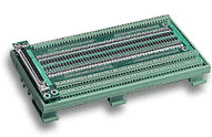
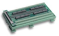
The ADLINK TB‑6231‑01 is a dedicated termination and interface board designed for use with the PXI‑7931 4×8 2‑Wire Matrix Switch Module. It provides a 62‑pin D‑Sub female connector interface for signal routing and configuration flexibility. The board enables multiple matrix configurations—such as 4×8, 4×4, 2×16, 2×8, and 2×4—by simple pad shorting on the terminal board. It is intended for laboratory, industrial, and automated test environments requiring flexible signal switching and matrix routing.
### 2. Key Features
- PXI Specification Compliance: Fully compliant with PXI Specifications Rev. 2.2 and CompactPCI standards (PICMG 2.0 R3.0 and PICMG 2.1 R2.0 Hot‑Swap).
- Flexible Matrix Configuration: Supports multiple matrix topologies selectable via the TB‑6231‑01 terminal board:
- One 4×8 matrix
- Two 4×4 matrices
- One 2×16 matrix
- Two 2×8 matrices
- Four 2×4 matrices
- High‑Performance Relay Array: Up to 32 cross‑point DPDT (2 Form C) non‑latching relays for 2‑wire switching.
- Electrical Ratings:
- 2 A switching and 2 A carrying current
- 220 V DC / 125 V AC maximum switching voltage
- 60 W maximum switching power
- Deterministic Scanning: Onboard 1 k‑sample scan list for deterministic relay sequencing.
- Synchronization: Handshaking signals and PXI trigger bus/star trigger support for multi‑module synchronization.
- Safety Functions: Hardware emergency shutdown and programmable watchdog timer (1 ms – 420 s).
- Auxiliary Digital I/O: Eight 3.3 V/TTL I/O channels (5 V tolerant) for general‑purpose control.
- Software Programmability: Fully software‑controlled relay configuration and scan sequencing.
- Operating System Support: Windows Vista/XP/2000/2003.
- Software Tools: Compatible with VB, VC++, BCB, Delphi, and DAQBench; driver support via ADL‑SWITCH for Windows.
- Safety‑Critical Design: Includes programmable relay safety states and watchdog protection for industrial reliability.
### 3. Technical Specifications
Physical Characteristics
- Form Factor: 3U Eurocard, CompactPCI compliant
- Dimensions: 160 mm (L) × 100 mm (H) (excluding connectors)
- Connector Type: 62‑pin D‑Sub female (on TB‑6231‑01)
- Weight: Approx. 200 g (typical for terminal board)
- Material: High‑grade FR‑4 PCB with screw‑terminal interface
Electrical Characteristics (PXI‑7931 Module)
- Relay Type: DPDT (2 Form C), non‑latching
- Number of Cross‑Points: 32 (2‑wire)
- Switching Current: 2 A max.
- Carrying Current: 2 A max.
- Switching Voltage: 220 V DC / 125 V AC max.
- Switching Power: 60 W (60 VA) max.
- Contact Resistance: ≤ 100 mΩ
- Operate/Release Time: 4 ms max. each
- Bounce Time: 1 ms max.
- Mechanical Life: ≥ 10⁸ operations
- Electrical Life: ≥ 5×10⁵ operations (1 A @ 30 V DC resistive)
- Failure Rate: 10 µA @ 10 mV DC
Environmental Conditions
- Operating Temperature: 0 °C to 55 °C
- Storage Temperature: –20 °C to 70 °C
- Relative Humidity: 5 % to 85 % (non‑condensing)
- EMC/EMI Compliance: CE and FCC Class A
Power Requirements (PXI‑7931)
- +5 V @ 1 A
- +3.3 V @ 400 mA
### 4. Functionality
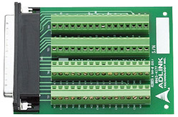
The TB‑6231‑01 serves as the termination interface for the PXI‑7931 matrix switch module. It routes the module’s 62‑pin D‑Sub male connector to user‑accessible screw terminals, allowing flexible signal wiring and reconfiguration.
Operation Principle:
- The PXI‑7931 uses 32 DPDT relays arranged in 4 banks of 2×4 2‑wire matrices.
- By shorting specific pads on the TB‑6231‑01, users can merge banks to form larger matrices (e.g., 4×8 or 2×16).
- Relay states are controlled via software commands or pre‑loaded scan lists stored in onboard memory.
- The scan list can advance automatically based on external triggers or internal timers, enabling deterministic test sequencing.
Use Cases and Applications:
- Automated test equipment (ATE) signal routing
- Industrial ON/OFF control and relay driving
- Laboratory automation and measurement switching
- Limit switch monitoring and contact sensing
- Integration with A/D and D/A modules for data acquisition systems
- Safety‑critical control systems requiring watchdog and emergency shutdown
Compatibility:
- Designed for PXI chassis compliant with PXI Rev. 2.2 and CompactPCI standards.
- Compatible with ADLINK ACL‑10262 62‑pin D‑Sub cable (1 m).
- Software integration via ADL‑SWITCH driver and DAQBench tools.
### 5. Components & Accessories
Included Items:
- TB‑6231‑01 Matrix Switch Termination Board (62‑pin D‑Sub female)
- User Manual and Documentation
Optional Accessories:
- ACL‑10262 Cable: 62‑pin D‑Sub male/female cable, 1 m length (for PXI‑7931 connection)
- PXI‑7931 Module: 4×8 2‑Wire Matrix Switch Module (required for operation)
Connectors:
- Front Panel: 62‑pin D‑Sub female connector
- Screw Terminals: for signal wiring and matrix configuration
- PXI Backplane Interface: via PXI‑7931 module
### 6. Installation & Setup
Requirements:
- PXI chassis compliant with PXI Rev. 2.2 and CompactPCI standards
- ADLINK PXI‑7931 module installed in the chassis
- Grounded anti‑static work surface and ESD protection
Installation Steps:
1. Power off the PXI chassis before inserting the module.
2. Align the PXI‑7931 module with the chassis card guide and insert until the ejector latch clicks.
3. Secure the front panel screws.
4. Attach the TB‑6231‑01 to the module’s 62‑pin connector directly or via the ACL‑10262 cable.
5. Configure the desired matrix topology by shorting pads on the TB‑6231‑01 as per the configuration table.
6. Connect signal wires to the screw terminals according to the pin assignment map.
7. Power on the PXI system and install the ADL‑SWITCH driver software.
Configuration:
- Matrix topology is defined by hardware pad shorting on the TB‑6231‑01.
- Relay control and scan list programming are performed through software commands via ADL‑SWITCH API.
- Handshaking and trigger sources can be assigned to AUX pins, PXI trigger bus, or star trigger lines.
### 7. Performance & Capabilities
Switching Performance:
- Operate/Release Time: ≤ 4 ms
- Bounce Time: ≤ 1 ms
- Switching Rate: Up to 200 operations per second
- Contact Resistance: ≤ 100 mΩ
- Isolation: High isolation between channels for low‑noise measurements
Capacity & Efficiency:
- 32 cross‑points allow complex signal routing within a compact PXI form factor.
- Supports deterministic scanning with 1 k‑sample scan list for automated test sequences.
- Multiple modules can be synchronized via PXI trigger bus or star trigger for expanded matrix capacity.
Limitations:
- Maximum switching voltage limited to 220 V DC / 125 V AC.
- Non‑latching relays require continuous power to maintain state.
- Not intended for high‑frequency RF applications or currents > 2 A.
### 8. Standards & Compliance
- PXI Specification: Rev. 2.2 compliant
- CompactPCI Compliance: PICMG 2.0 R3.0 and PICMG 2.1 R2.0 Hot‑Swap
- EMC/EMI Compliance: CE and FCC Class A
- Safety Design: Meets industrial safety requirements for emergency shutdown and watchdog protection
- Environmental Compliance: RoHS compliant materials and lead‑free construction
### 9. Additional Information
Warranty:
- Standard two‑year manufacturer’s warranty from ADLINK Technology Inc.
- Covers defects in materials and workmanship under normal use.
- Excludes damage from misuse, improper installation, or unauthorized repair.
Support & Service:
- Technical support via email: service@adlinktech.com
- Phone: +886‑2‑82265877 Fax: +886‑2‑82265717
- Website: [www.adlinktech.com](http://www.adlinktech.com)
- RMA and repair requests handled through ADLINK’s online RMA portal.
Maintenance:
- Periodic inspection of relay contacts and terminal connections recommended.
- Keep the board free of dust and moisture; store in anti‑static packaging when not in use.
- Firmware and driver updates available through ADLINK support portal.
Software Updates:
- ADL‑SWITCH driver package supports Windows 98/ME/NT/2000/XP/Vista/2003.
- Includes utilities for relay testing, scan list configuration, and sample source code in VB and VC++.
- For Linux or VxWorks support, contact ADLINK for custom drivers.
Manufacturer Information:
ADLINK Technology Inc.
9F, No. 166, Jian Yi Road, Chungho City, Taipei 235, Taiwan
### Summary
The ADLINK TB‑6231‑01 Matrix Switch Board is a precision termination interface designed for the PXI‑7931 4×8 2‑Wire Matrix Module, providing a flexible, configurable, and reliable platform for signal routing in automated test and measurement systems. With its 62‑pin D‑Sub female connector, multiple matrix configuration options, and robust electrical performance, it enables engineers to build scalable switching architectures within PXI systems.
The combination of the TB‑6231‑01 and PXI‑7931 offers deterministic scanning, programmable safety functions, and synchronization across multiple modules through PXI trigger bus and star trigger lines. Designed to meet industrial and laboratory standards, the system ensures high reliability, safety, and ease of integration with ADLINK’s software ecosystem.
In essence, the TB‑6231‑01 serves as the essential interface that transforms the PXI‑7931 module into a versatile, reconfigurable matrix switch solution for modern automated test environments.
-
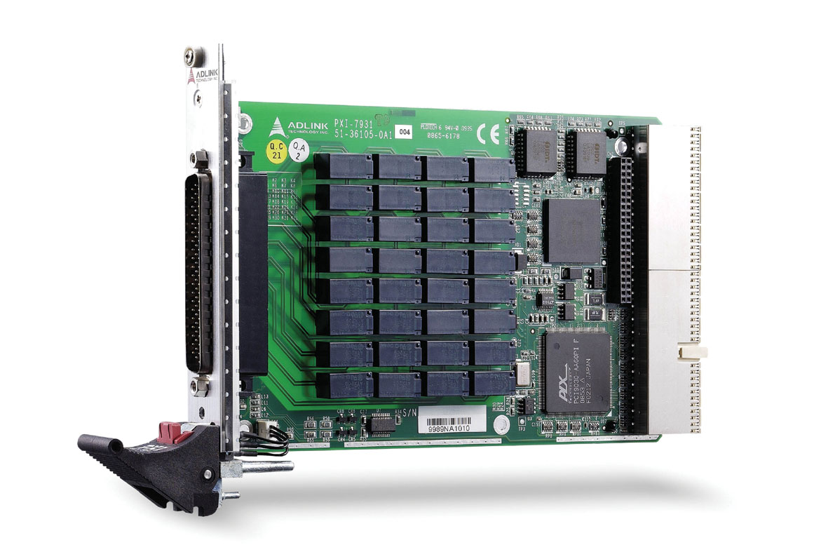
PXI-7931
- PXI cPCI 3U 32*Chan 2 Form C 4x8 Relay Card
-
ACL-10262-1
- 62-Pin D-sub male/female 1m cable

.webp)
 LOOKING FOR THE RIGHT
 PXI-7931_Datasheet_en_1.pdf
PDF Catalog
PXI-7931_Datasheet_en_1.pdf
PDF Catalog
 PXI-7931_Manual_1.pdf
Manual
PXI-7931_Manual_1.pdf
Manual