TB-6231-01
LOOKING FOR THE RIGHT
INDUSTRIAL SOLUTION?
Discover embedded, communication and automation solutions tailored to your application.
- PXI and CompactPCI Compliance:
Conforms to PXI Specification Rev. 2.2 and CompactPCI PICMG 2.0 R3.0 standards, ensuring interoperability with PXI-based test systems.
- Hot-Swap Capability:
Fully compliant with PICMG 2.1 R2.0 CompactPCI Hot Swap specifications, allowing module replacement without system shutdown.
- Flexible Matrix Configuration:
Default configuration is a 4-group 2x4 2-wire matrix. With the TB-6231-01 terminal board, users can reconfigure to one of several matrix topologies:
- 1 × 4x8
- 2 × 4x4
- 1 × 2x16
- 2 × 2x8
- 4 × 2x4
- Relay Characteristics:
- 32 DPDT (2 Form C) non-latching relays
- 2 A switching and carrying current
- 220 V DC / 125 V AC maximum switching voltage
- 60 W maximum switching power
- 100 mΩ maximum contact resistance
- 4 ms maximum operate and release time
- Safety and Reliability:
- Programmable emergency shutdown function
- 32-bit watchdog timer (1 ms to 420 s range)
- Hardware safety status monitoring
- Synchronization and Triggering:
- PXI trigger bus and star trigger support
- Programmable handshaking signals for external instrument synchronization
- Onboard 1 k-sample scan list for deterministic scanning
- Auxiliary Digital I/O:
- 8 channels of 3.3 V/TTL digital I/O (5 V tolerant)
- Dual-function pins for trigger and shutdown control
- Software and Driver Support:
- ADL-SWITCH driver for Windows 98/ME/NT/2000/XP/Vista/2003
- Compatible with VB, VC++, BCB, Delphi, and DAQBench
- Safety-Critical Design:
Designed for industrial and laboratory automation systems requiring deterministic control and fail-safe operation.
Conforms to PXI Specification Rev. 2.2 and CompactPCI PICMG 2.0 R3.0 standards, ensuring interoperability with PXI-based test systems.
- Hot-Swap Capability:
Fully compliant with PICMG 2.1 R2.0 CompactPCI Hot Swap specifications, allowing module replacement without system shutdown.
- Flexible Matrix Configuration:
Default configuration is a 4-group 2x4 2-wire matrix. With the TB-6231-01 terminal board, users can reconfigure to one of several matrix topologies:
- 1 × 4x8
- 2 × 4x4
- 1 × 2x16
- 2 × 2x8
- 4 × 2x4
- Relay Characteristics:
- 32 DPDT (2 Form C) non-latching relays
- 2 A switching and carrying current
- 220 V DC / 125 V AC maximum switching voltage
- 60 W maximum switching power
- 100 mΩ maximum contact resistance
- 4 ms maximum operate and release time
- Safety and Reliability:
- Programmable emergency shutdown function
- 32-bit watchdog timer (1 ms to 420 s range)
- Hardware safety status monitoring
- Synchronization and Triggering:
- PXI trigger bus and star trigger support
- Programmable handshaking signals for external instrument synchronization
- Onboard 1 k-sample scan list for deterministic scanning
- Auxiliary Digital I/O:
- 8 channels of 3.3 V/TTL digital I/O (5 V tolerant)
- Dual-function pins for trigger and shutdown control
- Software and Driver Support:
- ADL-SWITCH driver for Windows 98/ME/NT/2000/XP/Vista/2003
- Compatible with VB, VC++, BCB, Delphi, and DAQBench
- Safety-Critical Design:
Designed for industrial and laboratory automation systems requiring deterministic control and fail-safe operation.
Comprehensive Product Summary: ADLINK PXI-7931 4x8 2-Wire Matrix Module
### 1. Product Overview
- Product Name: PXI-7931
- Model Number: PXI-7931
- Series: PXI / CompactPCI 3U Switch Module Series
- Article Number: PXI-7931
- Manufacturer: ADLINK Technology Inc.
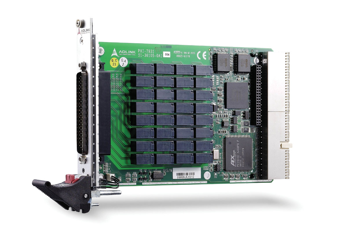
- Product Type: PXI cPCI 3U 32-Channel 2 Form C 4x8 Relay Card
- Form Factor: 3U Eurocard, CompactPCI (PICMG 2.0 R3.0 compliant)
- Bus Interface: PXI 3U CompactPCI Bus
- Manufacturer Website: [www.adlinktech.com](http://www.adlinktech.com)
- Country of Origin: Taiwan
The ADLINK PXI-7931 is a high-performance PXI matrix switch module designed for flexible signal routing and automated test applications. It integrates 32 cross-point, 2-wire, double-pole double-throw (DPDT, 2 Form C) non-latching relays, providing a configurable 4x8 matrix topology. The module is fully compliant with PXI and CompactPCI standards, supporting hot-swap functionality and synchronization through PXI trigger and star trigger buses.
### 2. Key Features
- PXI and CompactPCI Compliance:
Conforms to PXI Specification Rev. 2.2 and CompactPCI PICMG 2.0 R3.0 standards, ensuring interoperability with PXI-based test systems.
- Hot-Swap Capability:
Fully compliant with PICMG 2.1 R2.0 CompactPCI Hot Swap specifications, allowing module replacement without system shutdown.
- Flexible Matrix Configuration:
Default configuration is a 4-group 2x4 2-wire matrix. With the TB-6231-01 terminal board, users can reconfigure to one of several matrix topologies:
- 1 × 4x8
- 2 × 4x4
- 1 × 2x16
- 2 × 2x8
- 4 × 2x4
- Relay Characteristics:
- 32 DPDT (2 Form C) non-latching relays
- 2 A switching and carrying current
- 220 V DC / 125 V AC maximum switching voltage
- 60 W maximum switching power
- 100 mΩ maximum contact resistance
- 4 ms maximum operate and release time
- Safety and Reliability:
- Programmable emergency shutdown function
- 32-bit watchdog timer (1 ms to 420 s range)
- Hardware safety status monitoring
- Synchronization and Triggering:
- PXI trigger bus and star trigger support
- Programmable handshaking signals for external instrument synchronization
- Onboard 1 k-sample scan list for deterministic scanning
- Auxiliary Digital I/O:
- 8 channels of 3.3 V/TTL digital I/O (5 V tolerant)
- Dual-function pins for trigger and shutdown control
- Software and Driver Support:
- ADL-SWITCH driver for Windows 98/ME/NT/2000/XP/Vista/2003
- Compatible with VB, VC++, BCB, Delphi, and DAQBench
- Safety-Critical Design:
Designed for industrial and laboratory automation systems requiring deterministic control and fail-safe operation.
### 3. Technical Specifications
Physical Characteristics:
- Form Factor: 3U Eurocard (PXI / CompactPCI)
- Dimensions: 160 mm (L) × 100 mm (H) (excluding connectors)
- Weight: Approx. 0.5 kg (typical)
- Connector Type: 62-pin D-sub male (front panel I/O)
Electrical Characteristics:
- Power Requirements:
- +5 V @ 1 A
- +3.3 V @ 400 mA
- Relay Type: DPDT (2 Form C), non-latching
- Switching Capacity:
- 2 A max current
- 220 V DC / 125 V AC max voltage
- 60 W max power
- Contact Resistance: ≤ 100 mΩ
- Operate/Release Time: ≤ 4 ms each
- Mechanical Life: ≥ 10⁸ operations
- Electrical Life: ≥ 5×10⁵ operations (1 A @ 30 V DC resistive load)
Environmental Conditions:
- Operating Temperature: 0 °C to 55 °C
- Storage Temperature: -20 °C to 70 °C
- Relative Humidity: 5% to 85% non-condensing
- EMC/EMI Compliance: CE, FCC Class A
### 4. Functionality
The PXI-7931 functions as a programmable matrix switch module for routing multiple analog or digital signals in automated test systems. Each relay cross-point can connect or disconnect signal paths under software control, enabling flexible signal routing between instruments and devices under test (DUTs).
Operating Modes:
1. Direct-Update Mode:
Relays switch immediately upon receiving a software command. Recommended debounce time: ≥ 5 ms.
2. Auto-Scan Mode:
Uses onboard 1 k-sample scan list memory to store relay patterns and timing sequences. Supports deterministic scanning triggered by external instruments or internal timers.
Handshaking and Synchronization:
- Trigger In (TRG_IN): Accepts external trigger signals from PXI instruments or external devices.
- Scanner Advanced (S_ADV): Outputs a signal to indicate relay state stabilization, enabling synchronized measurements.
- PXI Trigger Bus and Star Trigger: Allow synchronization across multiple PXI modules without external wiring.
Safety Functions:
- Emergency Shutdown:
Logic-low active input (AUX2/SHDNn) sets relays to a predefined safe state.
- Watchdog Timer:
32-bit timer with 10 MHz base clock; automatically resets relay pattern if system control is lost.
Applications:
- Industrial ON/OFF control
- Signal routing and multiplexing
- Laboratory and production test automation
- External high-power relay driving
- Limit switch monitoring and contact sensing
- Integration with A/D and D/A modules for data acquisition systems
### 5. Components & Accessories
Included Items:
- PXI-7931 4x8 2-Wire Matrix PXI Switch Module
- User’s Manual (Part No. 50-17009-100)
- ADLINK Software CD (includes ADL-SWITCH driver and utilities)
- ADL-SWITCH User’s Guide
Optional Accessories:
- TB-6231-01 Terminal Board:
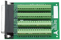
Multiplexer switch terminal board with one 62-pin D-sub female connector; supports multiple matrix configurations (2x4, 2x8, 2x16, 4x4, 4x8).
- ACL-10262 Cable:
62-pin D-sub male/female cable, 1 meter length, for connection between PXI-7931 and TB-6231-01.
Connectors:
- Front Panel: 62-pin D-sub male connector
- Rear Panel: PXI J1/J2 connectors for backplane communication
### 6. Installation & Setup
Requirements:
- PXI or CompactPCI chassis with available 3U slot
- Compatible PXI controller or embedded PC
- Windows-based operating system (XP, 2000, Vista, 2003)
Installation Steps:
1. Power off the PXI chassis before inserting the module (unless hot-swap is supported).
2. Align the PXI-7931 with the chassis card guide and slide it into the slot.
3. Push the ejector handle upward until the module clicks into place.
4. Tighten the front panel screws to secure the module.
5. Connect the TB-6231 terminal board or external wiring to the 62-pin D-sub connector.
6. Install the ADL-SWITCH driver and verify module recognition via the ADLINK utility.
Hot-Swap Procedure:
- Supported under Microsoft Embedded XP.
- For Windows 2000 or other OS, a dedicated hot-swap driver is required.
- Blue LED indicates readiness for removal; red latch must be pressed before extraction.
### 7. Performance & Capabilities
Switching Performance:
- Max Switching Current: 2 A
- Max Switching Voltage: 220 V DC / 125 V AC
- Max Switching Power: 60 W
- Relay Operation Speed: Up to 200 operations per second
- Debounce Time: 5 ms recommended
Scan List Operation:
- Memory Depth: 1024 entries
- Scan Delay Timer: Programmable per entry
- Trigger Sources: External (PXI trigger bus, star trigger, AUX1) or internal timer
- Synchronization: Multiple PXI-7931 modules can operate in parallel with deterministic timing.
Limitations:
- Non-latching relays require continuous power to maintain state.
- Maximum current and voltage ratings must not be exceeded to ensure relay longevity.
- AUX2 pin shares function with SHDNn; improper use may trigger shutdown.
### 8. Standards & Compliance
- PXI Specification: Rev. 2.2 compliant
- CompactPCI Specification: PICMG 2.0 R3.0 compliant
- Hot Swap Specification: PICMG 2.1 R2.0 compliant
- EMC/EMI: CE and FCC Class A certified
- Safety: Designed for safety-critical applications with watchdog and emergency shutdown features
- Environmental: RoHS compliant (based on ADLINK manufacturing standards)
### 9. Additional Information
Warranty:
- Duration: 2 years from factory shipment date
- Coverage: Free repair for defects in materials or workmanship
- Exclusions:
- Damage from misuse, improper installation, or environmental factors
- Unauthorized repairs or modifications
- Altered or missing serial numbers
- RMA Procedure:
Customers must obtain an RMA number and submit an application form via [http://rma.adlinktech.com/policy](http://rma.adlinktech.com/policy).
Support & Maintenance:
- Technical Support: service@adlinktech.com
- Phone: +886-2-82265877
- Fax: +886-2-82265717
- Address: 9F, No. 166, Jian Yi Road, Chungho City, Taipei 235, Taiwan
Software Updates:
- ADLINK provides periodic driver and firmware updates via its website.
- ADL-SWITCH driver package includes test utilities, sample code, and API documentation for integration with Visual Basic, C/C++, and Delphi environments.
Maintenance Recommendations:
- Operate within specified temperature and humidity ranges.
- Avoid exposure to dust, moisture, or corrosive environments.
- Periodically inspect connectors and relays for wear or contamination.
### Summary
The ADLINK PXI-7931 is a robust, software-programmable PXI matrix switch module engineered for automated test and measurement systems. Its 32 DPDT relays provide flexible signal routing in multiple matrix configurations, while its compliance with PXI and CompactPCI standards ensures seamless integration into modular test platforms. With advanced features such as deterministic scanning, programmable handshaking, watchdog safety mechanisms, and hot-swap capability, the PXI-7931 delivers high reliability and precision for industrial, laboratory, and production automation environments.
Its combination of electrical performance, configurability, and safety functions makes it an ideal choice for engineers seeking a dependable switching solution for complex test architectures.

### 1. Product Overview
- Product Name: PXI-7931
- Model Number: PXI-7931
- Series: PXI / CompactPCI 3U Switch Module Series
- Article Number: PXI-7931
- Manufacturer: ADLINK Technology Inc.
- Product Type: PXI cPCI 3U 32-Channel 2 Form C 4x8 Relay Card
- Form Factor: 3U Eurocard, CompactPCI (PICMG 2.0 R3.0 compliant)
- Bus Interface: PXI 3U CompactPCI Bus
- Manufacturer Website: [www.adlinktech.com](http://www.adlinktech.com)
- Country of Origin: Taiwan
The ADLINK PXI-7931 is a high-performance PXI matrix switch module designed for flexible signal routing and automated test applications. It integrates 32 cross-point, 2-wire, double-pole double-throw (DPDT, 2 Form C) non-latching relays, providing a configurable 4x8 matrix topology. The module is fully compliant with PXI and CompactPCI standards, supporting hot-swap functionality and synchronization through PXI trigger and star trigger buses.
### 2. Key Features
- PXI and CompactPCI Compliance:
Conforms to PXI Specification Rev. 2.2 and CompactPCI PICMG 2.0 R3.0 standards, ensuring interoperability with PXI-based test systems.
- Hot-Swap Capability:
Fully compliant with PICMG 2.1 R2.0 CompactPCI Hot Swap specifications, allowing module replacement without system shutdown.
- Flexible Matrix Configuration:
Default configuration is a 4-group 2x4 2-wire matrix. With the TB-6231-01 terminal board, users can reconfigure to one of several matrix topologies:
- 1 × 4x8
- 2 × 4x4
- 1 × 2x16
- 2 × 2x8
- 4 × 2x4
- Relay Characteristics:
- 32 DPDT (2 Form C) non-latching relays
- 2 A switching and carrying current
- 220 V DC / 125 V AC maximum switching voltage
- 60 W maximum switching power
- 100 mΩ maximum contact resistance
- 4 ms maximum operate and release time
- Safety and Reliability:
- Programmable emergency shutdown function
- 32-bit watchdog timer (1 ms to 420 s range)
- Hardware safety status monitoring
- Synchronization and Triggering:
- PXI trigger bus and star trigger support
- Programmable handshaking signals for external instrument synchronization
- Onboard 1 k-sample scan list for deterministic scanning
- Auxiliary Digital I/O:
- 8 channels of 3.3 V/TTL digital I/O (5 V tolerant)
- Dual-function pins for trigger and shutdown control
- Software and Driver Support:
- ADL-SWITCH driver for Windows 98/ME/NT/2000/XP/Vista/2003
- Compatible with VB, VC++, BCB, Delphi, and DAQBench
- Safety-Critical Design:
Designed for industrial and laboratory automation systems requiring deterministic control and fail-safe operation.
### 3. Technical Specifications
Physical Characteristics:
- Form Factor: 3U Eurocard (PXI / CompactPCI)
- Dimensions: 160 mm (L) × 100 mm (H) (excluding connectors)
- Weight: Approx. 0.5 kg (typical)
- Connector Type: 62-pin D-sub male (front panel I/O)
Electrical Characteristics:
- Power Requirements:
- +5 V @ 1 A
- +3.3 V @ 400 mA
- Relay Type: DPDT (2 Form C), non-latching
- Switching Capacity:
- 2 A max current
- 220 V DC / 125 V AC max voltage
- 60 W max power
- Contact Resistance: ≤ 100 mΩ
- Operate/Release Time: ≤ 4 ms each
- Mechanical Life: ≥ 10⁸ operations
- Electrical Life: ≥ 5×10⁵ operations (1 A @ 30 V DC resistive load)
Environmental Conditions:
- Operating Temperature: 0 °C to 55 °C
- Storage Temperature: -20 °C to 70 °C
- Relative Humidity: 5% to 85% non-condensing
- EMC/EMI Compliance: CE, FCC Class A
### 4. Functionality
The PXI-7931 functions as a programmable matrix switch module for routing multiple analog or digital signals in automated test systems. Each relay cross-point can connect or disconnect signal paths under software control, enabling flexible signal routing between instruments and devices under test (DUTs).
Operating Modes:
1. Direct-Update Mode:
Relays switch immediately upon receiving a software command. Recommended debounce time: ≥ 5 ms.
2. Auto-Scan Mode:
Uses onboard 1 k-sample scan list memory to store relay patterns and timing sequences. Supports deterministic scanning triggered by external instruments or internal timers.
Handshaking and Synchronization:
- Trigger In (TRG_IN): Accepts external trigger signals from PXI instruments or external devices.
- Scanner Advanced (S_ADV): Outputs a signal to indicate relay state stabilization, enabling synchronized measurements.
- PXI Trigger Bus and Star Trigger: Allow synchronization across multiple PXI modules without external wiring.
Safety Functions:
- Emergency Shutdown:
Logic-low active input (AUX2/SHDNn) sets relays to a predefined safe state.
- Watchdog Timer:
32-bit timer with 10 MHz base clock; automatically resets relay pattern if system control is lost.
Applications:
- Industrial ON/OFF control
- Signal routing and multiplexing
- Laboratory and production test automation
- External high-power relay driving
- Limit switch monitoring and contact sensing
- Integration with A/D and D/A modules for data acquisition systems
### 5. Components & Accessories
Included Items:
- PXI-7931 4x8 2-Wire Matrix PXI Switch Module
- User’s Manual (Part No. 50-17009-100)
- ADLINK Software CD (includes ADL-SWITCH driver and utilities)
- ADL-SWITCH User’s Guide
Optional Accessories:
- TB-6231-01 Terminal Board:
Multiplexer switch terminal board with one 62-pin D-sub female connector; supports multiple matrix configurations (2x4, 2x8, 2x16, 4x4, 4x8).
- ACL-10262 Cable:
62-pin D-sub male/female cable, 1 meter length, for connection between PXI-7931 and TB-6231-01.
Connectors:
- Front Panel: 62-pin D-sub male connector
- Rear Panel: PXI J1/J2 connectors for backplane communication
### 6. Installation & Setup
Requirements:
- PXI or CompactPCI chassis with available 3U slot
- Compatible PXI controller or embedded PC
- Windows-based operating system (XP, 2000, Vista, 2003)
Installation Steps:
1. Power off the PXI chassis before inserting the module (unless hot-swap is supported).
2. Align the PXI-7931 with the chassis card guide and slide it into the slot.
3. Push the ejector handle upward until the module clicks into place.
4. Tighten the front panel screws to secure the module.
5. Connect the TB-6231 terminal board or external wiring to the 62-pin D-sub connector.
6. Install the ADL-SWITCH driver and verify module recognition via the ADLINK utility.
Hot-Swap Procedure:
- Supported under Microsoft Embedded XP.
- For Windows 2000 or other OS, a dedicated hot-swap driver is required.
- Blue LED indicates readiness for removal; red latch must be pressed before extraction.
### 7. Performance & Capabilities
Switching Performance:
- Max Switching Current: 2 A
- Max Switching Voltage: 220 V DC / 125 V AC
- Max Switching Power: 60 W
- Relay Operation Speed: Up to 200 operations per second
- Debounce Time: 5 ms recommended
Scan List Operation:
- Memory Depth: 1024 entries
- Scan Delay Timer: Programmable per entry
- Trigger Sources: External (PXI trigger bus, star trigger, AUX1) or internal timer
- Synchronization: Multiple PXI-7931 modules can operate in parallel with deterministic timing.
Limitations:
- Non-latching relays require continuous power to maintain state.
- Maximum current and voltage ratings must not be exceeded to ensure relay longevity.
- AUX2 pin shares function with SHDNn; improper use may trigger shutdown.
### 8. Standards & Compliance
- PXI Specification: Rev. 2.2 compliant
- CompactPCI Specification: PICMG 2.0 R3.0 compliant
- Hot Swap Specification: PICMG 2.1 R2.0 compliant
- EMC/EMI: CE and FCC Class A certified
- Safety: Designed for safety-critical applications with watchdog and emergency shutdown features
- Environmental: RoHS compliant (based on ADLINK manufacturing standards)
### 9. Additional Information
Warranty:
- Duration: 2 years from factory shipment date
- Coverage: Free repair for defects in materials or workmanship
- Exclusions:
- Damage from misuse, improper installation, or environmental factors
- Unauthorized repairs or modifications
- Altered or missing serial numbers
- RMA Procedure:
Customers must obtain an RMA number and submit an application form via [http://rma.adlinktech.com/policy](http://rma.adlinktech.com/policy).
Support & Maintenance:
- Technical Support: service@adlinktech.com
- Phone: +886-2-82265877
- Fax: +886-2-82265717
- Address: 9F, No. 166, Jian Yi Road, Chungho City, Taipei 235, Taiwan
Software Updates:
- ADLINK provides periodic driver and firmware updates via its website.
- ADL-SWITCH driver package includes test utilities, sample code, and API documentation for integration with Visual Basic, C/C++, and Delphi environments.
Maintenance Recommendations:
- Operate within specified temperature and humidity ranges.
- Avoid exposure to dust, moisture, or corrosive environments.
- Periodically inspect connectors and relays for wear or contamination.
### Summary
The ADLINK PXI-7931 is a robust, software-programmable PXI matrix switch module engineered for automated test and measurement systems. Its 32 DPDT relays provide flexible signal routing in multiple matrix configurations, while its compliance with PXI and CompactPCI standards ensures seamless integration into modular test platforms. With advanced features such as deterministic scanning, programmable handshaking, watchdog safety mechanisms, and hot-swap capability, the PXI-7931 delivers high reliability and precision for industrial, laboratory, and production automation environments.
Its combination of electrical performance, configurability, and safety functions makes it an ideal choice for engineers seeking a dependable switching solution for complex test architectures.
-
PXI-7931_Datasheet_en_1.pdf
PDF Catalog
-
PXI-7931_Manual_1.pdf
Manual
- TB-6231-01 - Matrix Switch Board 62-Pin D-Sub w/o cable
- ACL-10262-1 - 62-Pin D-sub male/female 1m cable